4 layers52.7 × 60.9 mm

 NidasioAlberto/signal-generator3
Signal Generator with an STM32
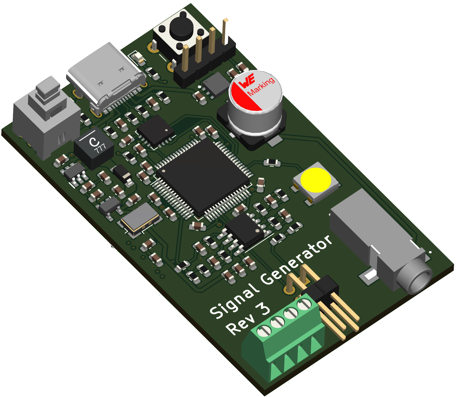
Signal generator is an open-source printed circuit board by NidasioAlberto, from the NidasioAlberto/signal-generator repository on GitHub. It is a 4-layer board of 36 × 60 mm with 70 parts on 89 nets, routed with 315 tracks and 57 vias.
It is built around the FT230XQ-R, TLV61048DBV and MEM2080-00-128-00-A, with the LD39050PU33R and LDK320AM120R among its other parts. Its parts include 30 capacitors, 20 resistors, 7 ICs, 6 connectors and 4 diodes. It belongs with the STM32 boards of this library.


The main idea of this project is to develop a waveform generator instrument using an STM32 microcontroller and its built-in DAC. The project has 2 parts:
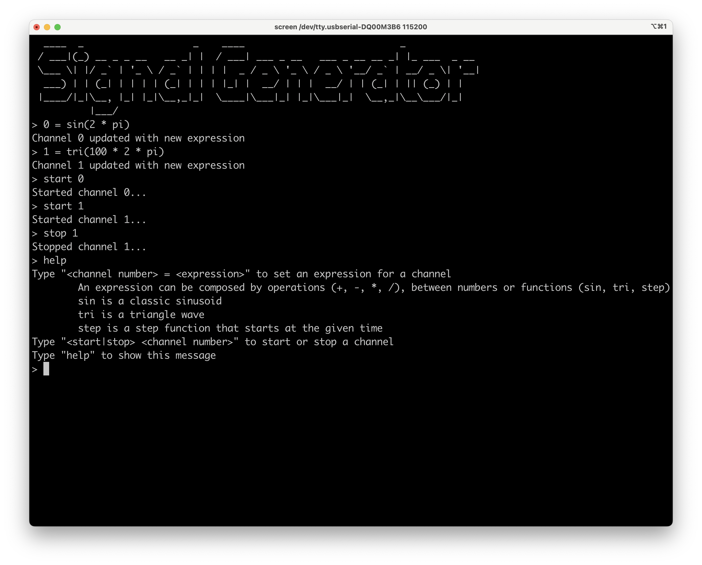
To achieve this goals a custom board was designed and software drivers were developed for the DAC and DMA. The final product also includes a text interface where the user can setup an arbitrary waveform and the device parses the user input using Flex and Bison.
The stm32 incorporates a Digital-to-Analog Converter (DAC) with an integrated output buffer. When enabled, the buffer allows the DAC to drive external loads directly. However, this comes at the cost of limited driving capability, especially when interfacing with capacitive loads. Disabling the buffer offers a pure analog output, but necessitates an external buffer or amplifier to drive any meaningful external load. The inherent impedance of the DAC's output pin can also cause distortions and constrain the signal's frequency, particularly when dealing with capacitive loads.
Integrating an external operational amplifier (op-amp) into the analog front-end offers multiple advantages:
Given that the board is powered via USB, which typically provides 5V, there's a need to step up this voltage to achieve the 12V requirement for the analog front end:
The opamp circuit also features a voltage divider to feedback the output signal to the STM32's ADC. This could allow the microcontroller to perform automatic calibration of the opamp gains. Here's the provided LaTeX content converted into markdown:
The STM32F205 is a low-end microcontroller with a 120MHz clock speed, 128KB of RAM, and the required peripherals needed by the project (DAC, DMA, and timers). It was used mainly because it was already stocked in the lab.
The board also features:
The software powering the signal generator board is built upon the Miosix operating system and features 2 main components:
The STM32F205 microcontroller is equipped with a versatile Digital-to-Analog Converter (DAC) peripheral that offers 12-bit resolution and two separate channels, effectively incorporating two DACs. This dual-channel architecture permits simultaneous generation of two distinct analog outputs, allowing our custom board to feature two independent output channels.
The DAC's conversion process can be initiated through multiple methods. It can be triggered manually via software, which provides direct control over the conversion timing. Alternatively, for applications requiring precise and periodic analog outputs, external triggers can be employed. A common external trigger source is a timer, which can initiate DAC conversions at predetermined intervals, ensuring consistent waveform generation.
The STM32's DAC is also designed with the capability to generate DMA requests. Once the DAC is ready for new data, it can signal the DMA peripheral to fetch the next data sample. The DMA (Direct Memory Access) controller is a powerful tool designed to handle data transfers independently of the CPU's operation. This peripheral is characterized by sixteen independent streams, each of which can be paired with different peripherals, granting a wide range of configuration possibilities. By leveraging the DMA's rapid data transfer capabilities, the DAC can be persistently supplied with data while leaving the CPU time to generate new data samples or perform other tasks.
One of its standout features is the double buffering mode. This mode uses two memory pointers: while one buffer is actively engaged by the DMA stream, the other can be prepared by the CPU, ensuring uninterrupted data flow.
In the context of the signal generator project, the DMA plays a crucial role. Each DAC is set up to utilize an external trigger originating from a timer. With every trigger event, the DAC issues a DMA request for a new data sample. The DMA has been configured in double buffer mode. Alternatively, a single buffer mode combined with the half-transfer interrupt could have been adopted to achieve a similar result. This integration of the DAC with the DMA and a timer is what ultimately powers the project's ability to generate high-frequency waveforms even with a low-end microcontroller such as the STM32F205.
The developed drivers are C++ classes that abstract the peripherals and allow the programmer to easily configure and use them. In particular, the DMA driver is divided into two classes and one struct:
The project achieved two concrete outcomes:
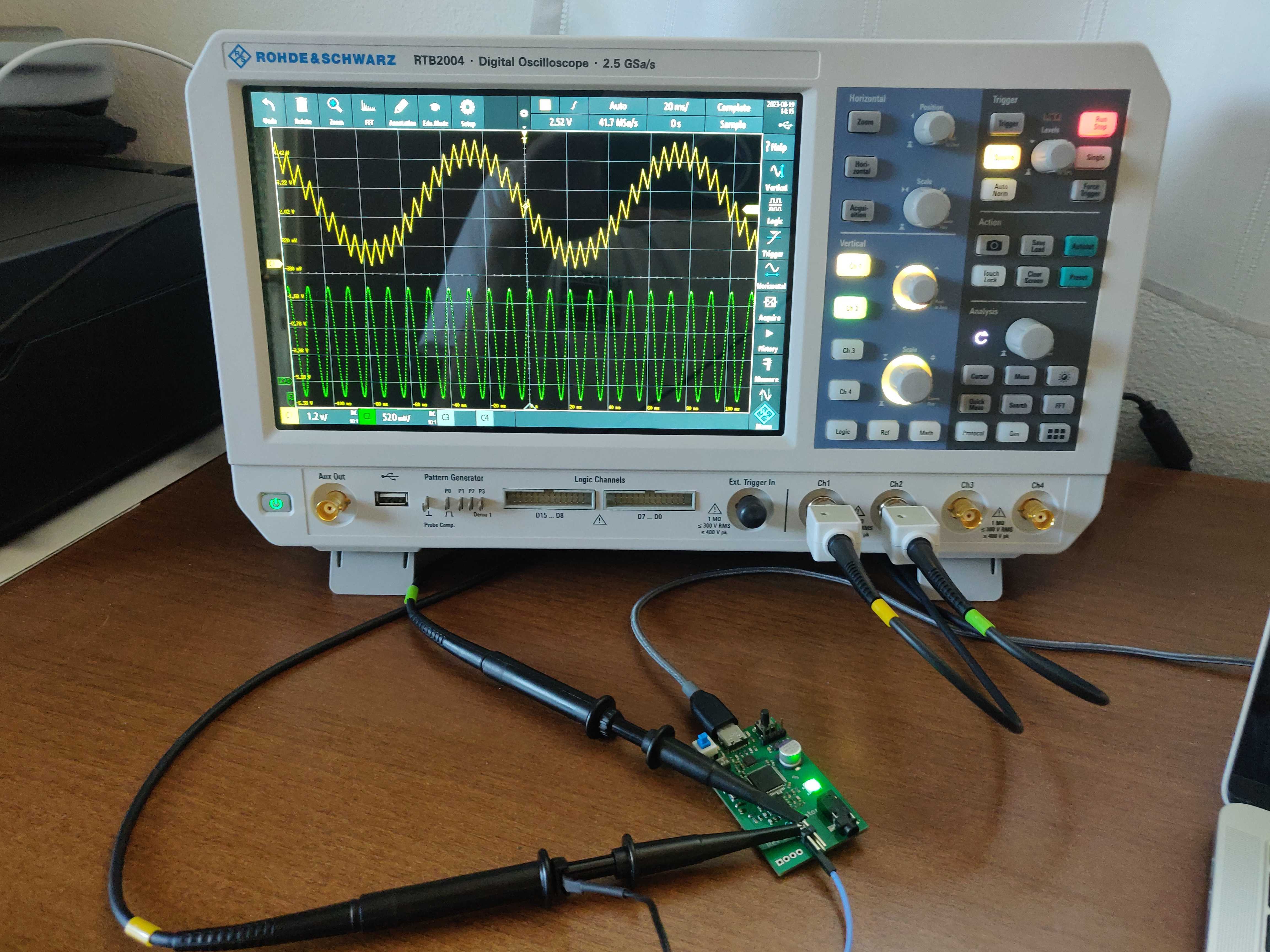
Developing both the hardware and the software allowed me not only to learn about the STM32 microcontroller and its peripherals but also to learn about the whole process of designing and assembling a PCB.
Particular effort went into the design of the board itself, selecting and sourcing the components, and manually assembling the board. It was a challenge because, being my first time creating a complex PCB with a microcontroller, I was not well prepared. I had to learn about the different types of components, which were required for my design, and which not. Some special takeaways were the importance of reading carefully the components datasheet, finding application notes to understand similar projects, and learning how to design and order a PCB (with KiCad and JLCPCB).
The assembly of the board was the most exciting part because I got to see my design come to life. I procured the necessary soldering equipment (solder paste, a hot plate, a hot air gun, and a microscope) and I soldered the board first by distributing the solder paste with a stencil and then by heating the board with the hot plate for the top layer, and with the hot air gun for the bottom layer. I had to learn how to use the equipment and how to solder the different components.
The software side was instead more akin to my previous experiences. I had already worked with microcontrollers and already used the Miosix operating system. However, I had never worked with the DMA peripheral. The most challenging aspects were understanding how the peripherals work by reading the reference manual and also finding examples online which are hard to come by.
The most useful knowledge that helped me in this project came from 3 sources:
The worst setback I faced was the board redesign. In the first version, I used an STM32F103 which is a cheaper microcontroller that has no built-in DAC! I realized this only after I had assembled the board and tried to use it. I had to adjust the schematic and the PCB in order to use the STM32F205 instead and reorder the board.
Once the board was ready I faced other problems during the development of the drivers but I managed to solve them without major issues. In this process, the debugger was particularly useful to understand what was going on.
| Qty | Value | Footprint | References |
|---|---|---|---|
| 12 | 100n | Capacitor_SMD:C_0603_1608Metric | C3, C6, C7, C8, C12, C16, C17, C18, C19, C20, C21, C23 |
| 6 | 1u | Capacitor_SMD:C_0603_1608Metric | C22, C25, C26, C27, C29, C30 |
| 2 | 0.5p | Capacitor_SMD:C_0603_1608Metric | C9, C10 |
| 2 | 1.33k | Resistor_SMD:R_0603_1608Metric | R8, R10 |
| 2 | 10u | Capacitor_SMD:C_0603_1608Metric | C1, C28 |
| 2 | 2.2u | Capacitor_SMD:C_0603_1608Metric | C14, C15 |
| 2 | 240k | Resistor_SMD:R_0603_1608Metric | R13, R15 |
| 2 | 27 | Resistor_SMD:R_0603_1608Metric | R1, R2 |
| 2 | 4.75k | Resistor_SMD:R_0603_1608Metric | R7, R9 |
| 2 | 46.4k | Resistor_SMD:R_0603_1608Metric | R11, R12 |
| 2 | 47p | Capacitor_SMD:C_0603_1608Metric | C4, C5 |
| 2 | 5.1k | Resistor_SMD:R_0603_1608Metric | R3, R4 |
| 2 | 91k | Resistor_SMD:R_0603_1608Metric | R14, R16 |
| 1 | 1.54M | Capacitor_SMD:C_0603_1608Metric | R19 |
| 1 | 100k | Capacitor_SMD:C_0603_1608Metric | R20 |
| 1 | 100p | Capacitor_SMD:C_0603_1608Metric | C11 |
| 1 | 10k | Resistor_SMD:R_0603_1608Metric | R18 |
| 1 | 1k | Resistor_SMD:R_0603_1608Metric | R17 |
| 1 | 3.32 | Resistor_SMD:R_0603_1608Metric | R5 |
| 1 | 330u | Signal Generator Components:WCAP-PSHP | C2 |
| 1 | 4.7u | Signal Generator Components:XAL4030 | L1 |
| 1 | 4.7u | Capacitor_SMD:C_0603_1608Metric | C24 |
| 1 | 43.2 | Resistor_SMD:R_0603_1608Metric | R6 |
| 1 | 6.8u | Capacitor_SMD:C_0603_1608Metric | C13 |
| 1 | AudioJack3 | Signal Generator Components:SJ-3523-SMT-TR | J1 |
| 1 | Conn_01x04 | Connector_PinHeader_2.54mm:PinHeader_1x04_P2.54mm_Vertical | J6 |
| 1 | Conn_02x02_Odd_Even | Connector_PinHeader_2.54mm:PinHeader_2x02_P2.54mm_Horizontal | J2 |
| 1 | D_Zener | Signal Generator Components:BZT52C10-TP | D4 |
| 1 | FT230XQ | Package_DFN_QFN:QFN-16-1EP_4x4mm_P0.65mm_EP2.1x2.1mm | U1 |
| 1 | FT5HN | Oscillator:Oscillator_SMD_Fox_FT5H_5.0x3.2mm | U4 |
| 1 | IN-PI55QA | Signal Generator Components:IN-PI55QA | D3 |
| 1 | LD39050PU33R | Signal Generator Components:LD39050PU33R | U5 |
| 1 | LDK320AM120R | Signal Generator Components:LDK320AM120R | U7 |
| 1 | LED Blue | LED_SMD:LED_0603_1608Metric | D1 |
| 1 | LED Orange | LED_SMD:LED_0603_1608Metric | D2 |
| 1 | MEM2080-00-128-00-A | Signal Generator Components:MEM2080-00-128-00-A | J4 |
| 1 | Opamp_Dual | Package_SO:SOIC-8_3.9x4.9mm_P1.27mm | U2 |
| 1 | STM32F205RCTx | Package_QFP:LQFP-64_10x10mm_P0.5mm | U3 |
| 1 | SW_Push | Button_Switch_THT:SW_PUSH_6mm_H5mm | SW1 |
| 1 | SW_SPDT | Signal Generator Components:Push Button Switch 7x7mm | SW2 |
| 1 | Screw_Terminal_01x04 | TerminalBlock_Phoenix:TerminalBlock_Phoenix_MPT-0,5-4-2.54_1x04_P2.54mm_Horizontal | J3 |
| 1 | TLV61048 | Signal Generator Components:TLV61048 | U6 |
| 1 | USB_C_Receptacle_USB2.0 | Signal Generator Components:USB4105-GF-A | J5 |


stanleyondrus/ILDAWaveX16
ILDAWaveX16 is an open-source, high-resolution, wireless laser DAC with SD-card playback, network control, and ILDA output.

FabianSchwartau/OBSPro
Version of the OpenBikeSensor hardware optimized for PCBA

mpiraux/OpenTRV-ESP
An open-source and open-hardware thermostatic radiator valve based on the ESP32C6 and the 28BYJ-48 stepper motor.

marcusmueller/12V_step_up
General purpose Step-Up converter

Pollex/MFM-Module-RS485
A MultiFlexMeter (MFM) sensor module. The hardware is a generic carrier: RS-485 + 1-Wire, with a software-selectable sensor supply rail (3.6 V / 5 V / 12 V).
It measures 36 × 60 mm and has 4 copper layers, 1.6 mm thick.
70 parts, built around the FT230XQ-R, TLV61048DBV, MEM2080-00-128-00-A and LD39050PU33R. The full list of its parts is on this page, with links to each part's symbol and footprint where PCBKit's library has them.
From the NidasioAlberto/signal-generator repository on GitHub, at the commit this page was made from: the board is pcb/Signal Generator.kicad_pcb and its schematic pcb/MCU.kicad_sch. PCBKit opens the board in the browser, with nothing to install.
Its repository states no licence, so its author keeps all rights: ask NidasioAlberto before reusing the design.