2 layers80 × 22 mm

 marcusmueller/12V_step_up
General purpose Step-Up converter
General purpose step up is an open-source printed circuit board by marcusmueller, from the marcusmueller/12V_step_up repository on GitHub, published under the CERN-OHL-S-2.0 licence. It is a 2-layer board of 32 × 46 mm with 26 parts on 20 nets, routed with 111 tracks and 28 vias.
It is built around the TLV61048DBV, GT-USB-7010ASV and SK1045B. Its parts include 8 resistors, 6 connectors, 3 capacitors, 1 IC and 1 diode.


Was warm. Did not find a good source for an affordable, compact, not-made-of-counterfeit-components step-up converter. Designed something that JLC would manufacture for me.
Note this was an exercise in rapid design, more than beauty.
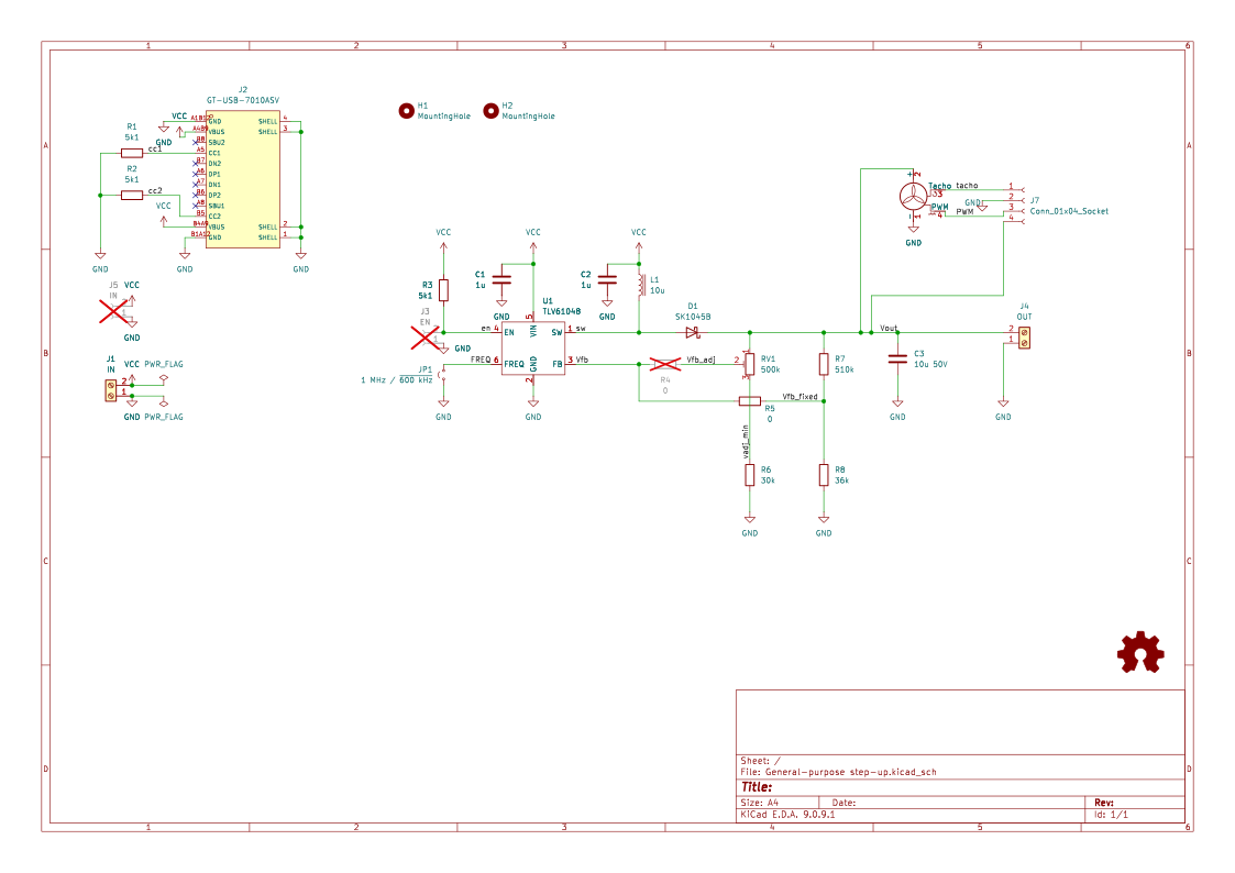
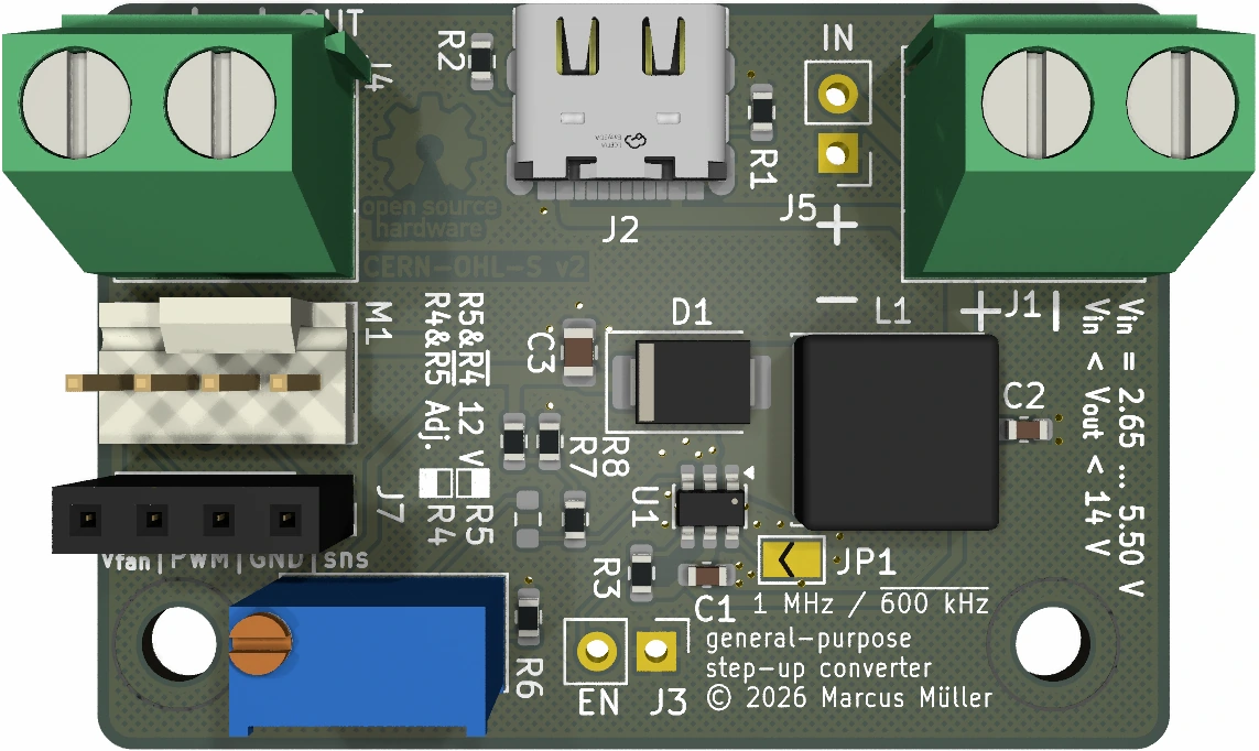
CERN-OHL-S v2 for the schematic, layout and TLV symbol.
The footprint and symbol for the USB connector have been sourced from JLC/LCSC's EasyEDA library, https://www.lcsc.com/product-detail/C2988369.html , and converted to KiCAD automatically. License there is
All elements of the Services, including without limitation the general design and the Content, are protected by trade dress, copyright, moral rights, trademark, and other laws relating to intellectual property rights. The Services may only be used for the intended purpose for which such Web Site and Services are being made available.
and I think "purpose of being made available" here is use for designing electronics with LCSC parts / for JLCPCB production.
Not being super happy about that, I'm not including them as redistributable in the sources here, but here's how you can get them.
uv; we'll use it to run the JLC2KiCadLib tool without permanent installation.uvx to run the tool:
cd parts
uvx JLC2KiCadLib C2988369Everything aside from the USB-C connector should be pretty feasible to solder by hand with a fine-ish tip, if you did any SMD work before.
Used the fabrication plugin, installed directly from KiCAD's plugin manager. UI isn't great, the results just work, so that's an endorsement of sorts.
Because I'd have to have ordered the parts in small quantities myself, I however fell back to letting JLCPCB assemble the board, minus screw and pin header connectors; thus, a few, non-basic parts, for which you pay extra tooling fees per BOM line, exist:
These are the main assembly cost drivers, and if you can solder them yourself, you'll save a bit. However, at quantity of five, the per-board cost including shipping and parts was below 10€, and thus, the extra shipping costs needed to get these components elsewhere would have more than eaten JLC's extended part costs. (And in fact, getting these boards manufactured thus proved cheaper than soldering any of these myself, since I would also have paid more for each part.)
The things I did hand-solder were the screw connectors (which I don't need on most of the individual boards) and the fan connector – had 2-pin JST-compatible 2.54mm headers lying around (and the fan only needs supply voltage and ground).
| Qty | Value | Footprint | References |
|---|---|---|---|
| 3 | 5k1 | Resistor_SMD:R_0603_1608Metric | R1, R2, R3 |
| 2 | 0 | Resistor_SMD:R_0603_1608Metric | R4, R5 |
| 2 | 1u | Capacitor_SMD:C_0603_1608Metric | C1, C2 |
| 2 | MountingHole | MountingHole:MountingHole_3.2mm_M3_DIN965 | H1, H2 |
| 1 | 1 MHz / ~{600 kHz} | Jumper:SolderJumper-2_P1.3mm_Open_TrianglePad1.0x1.5mm | JP1 |
| 1 | 10u | Inductor_SMD:L_Sunlord_SWPA8040S | L1 |
| 1 | 10u 50V | Capacitor_SMD:C_0805_2012Metric | C3 |
| 1 | 30k | Resistor_SMD:R_0603_1608Metric | R6 |
| 1 | 36k | Resistor_SMD:R_0603_1608Metric | R8 |
| 1 | 500k | Potentiometer_THT:Potentiometer_Bourns_3296W_Vertical | RV1 |
| 1 | 510k | Resistor_SMD:R_0603_1608Metric | R7 |
| 1 | Conn_01x04_Socket | Connector_PinSocket_2.54mm:PinSocket_1x04_P2.54mm_Vertical | J7 |
| 1 | EN | Connector_PinHeader_2.54mm:PinHeader_1x02_P2.54mm_Vertical | J3 |
| 1 | Fan_4pin | Connector:FanPinHeader_1x04_P2.54mm_Vertical | M1 |
| 1 | GT-USB-7010ASV | footprint:USB-C-SMD_G-SWITCH_GT-USB-7010ASV | J2 |
| 1 | IN | Connector_PinHeader_2.54mm:PinHeader_1x02_P2.54mm_Vertical | J5 |
| 1 | IN | TerminalBlock_Phoenix:TerminalBlock_Phoenix_MKDS-1,5-2-5.08_1x02_P5.08mm_Horizontal | J1 |
| 1 | Logo_Open_Hardware_Small | Symbol:OSHW-Logo_5.7x6mm_Copper | SYM1 |
| 1 | OUT | TerminalBlock_Phoenix:TerminalBlock_Phoenix_MKDS-1,5-2-5.08_1x02_P5.08mm_Horizontal | J4 |
| 1 | SK1045B | Diode_SMD:D_SMB | D1 |
| 1 | TLV61048 | Package_TO_SOT_SMD:SOT-23-6 | U1 |

stanleyondrus/ILDAWaveX16
ILDAWaveX16 is an open-source, high-resolution, wireless laser DAC with SD-card playback, network control, and ILDA output.

FabianSchwartau/OBSPro
Version of the OpenBikeSensor hardware optimized for PCBA


mpiraux/OpenTRV-ESP
An open-source and open-hardware thermostatic radiator valve based on the ESP32C6 and the 28BYJ-48 stepper motor.

Pollex/MFM-Module-RS485
A MultiFlexMeter (MFM) sensor module. The hardware is a generic carrier: RS-485 + 1-Wire, with a software-selectable sensor supply rail (3.6 V / 5 V / 12 V).


It measures 32 × 46 mm and has 2 copper layers, 1.6 mm thick.
26 parts, built around the TLV61048DBV, GT-USB-7010ASV and SK1045B. The full list of its parts is on this page, with links to each part's symbol and footprint where PCBKit's library has them.
From the marcusmueller/12V_step_up repository on GitHub, at the commit this page was made from: the board is General-purpose step-up.kicad_pcb and its schematic General-purpose step-up.kicad_sch. PCBKit opens the board in the browser, with nothing to install.
Its repository publishes it under the CERN-OHL-S-2.0 licence: you may reuse it on that licence's terms (keep the author's notice, and for a copyleft licence share your changes alike).