2 layers95 × 80 mm
 NdK73/HomeAutomation5
DomoNode, DomoNode-inout, DomoDisp, etc.
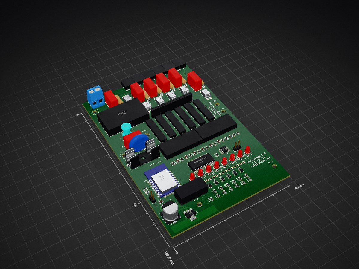
Domonode2 is an open-source printed circuit board by NdK73, from the NdK73/HomeAutomation repository on GitHub. It is a 2-layer board of 95 × 139.6 mm with 111 parts on 111 nets, routed with 893 tracks and 15 vias.
It is built around the HLK-PM01, TLP620 and 24LC024/P. Its parts include 42 resistors, 16 capacitors, 12 connectors, 11 ICs and 8 diodes. It belongs with the ESP8266 boards of this library.


This project consists of a protocol spec, the design files for physical nodes and the source code that glues it together.
Full protocol description is available, together with examples of a monitor and a sender. The protocol is text-based to ease debugging.
ClearSky technology inside: the basic concept is that no coordinator is needed for the nodes to work after the initial configuration. There must not be a single point of (catastrophic) failure. And obviously no "cloud" (hence ClearSky) service is needed either: you, and only you, decide if/when/which data can exit from your network!
The most critical element is currently the access point, that is so cheap that having a cold-standby one should not be a problem.
Messages must support authentication and encryption to guarantee that confidential packets or dangerous commands are actually sent from an authorized source.
Warning: protocol is still work in progress and unstable: non-backward-compatible changes are still possible! Only after 1.0.0 milestone changes that introduce incompatibilities will be delayed till 2.0.0 .
All HW designs were in KiCAD 4.0.x (will follow what's packaged in latest Ubuntu LTS) so not to require nonstandard installs. But 5.x introduced too many new features not to be used, and it's "easy enough" to install (official instructions).
DIN-rail mounted devices are designed for the 6-modules AK-DR-04C enclosure. Note: these enclosures won't fit in a standard DIN rail box, unless you can move the rail further from the front panel (like in Gewiss GW40030).
Other devices are designed to be compatible with Vimar Plana series, but should fit other series with minor adjustements.
In the given layouts I use KF2EDGK right-angle (KF-2P, KF-4P or KF-6P) 5.08mm (or 3.81mm) pitch connectors so I can detach the node from power without having exposed wires with dangerous voltage laying around (and can reconnect it quickly and safely). Be sure to buy the angled version or you'll have a lot of extra work to bend the pins!
Warning: I did my best to keep the costs down without sacrificing security. Choice of the power brick is really important for security: never use HLK-PM01 clones unless you know what you're doing -- and even then it's better to avoid using 'em! If in doubt buy directly from Hi-Link (sorry, plain http, not https...). Probably the boards can't pass CE certification only because of conducted emissions, but since I don't have access to test equipment use at your own risk (or have 'em certified).
SSRs and relays should always be sourced from reputable sources. If in doubt, do not load 'em near the limits. For example never try a 400W load on a 2A SSR -- use a servo-relay. 2A SSRs are good for a couple of LED lamps, or a 40W bulb.
A node based on ESP8266 to be mounted in a 6-modules DIN rail enclosure.
Provides 4 SSR outputs and an expansion bus connector.
[OSHW] IT000001 | Certified open source hardware
Evolution of DomoNode, but offers 6 inputs @ 230V, 6 SSR 2A@230V (each one have its own independent in and out lines, for maximum flexibility) and 8 independent LEDs, still in a 6-modules DIN rail enclosure. Kept SW compatibility with basic DomoNode (just the first 4 outputs), but different external connections.
To better follow the norms, now inputs are on the top and outputs at the bottom.
Same expansion bus connector as the DomoNode 1.1.
I kept 2mm between L and N lines and it ought to be double-insulation, but it's actually not required: the user can't touch anything that is not already expected to be at 230V (screws in connectors) without opening the enclosure (the expansion connector MUST NOT be exposed).
The board requires two v-cuts around the central part, drawn on ECO2 layer (but not visible in the image). Once the two boards gets separated, the smaller one have to be mounted over the bigger one, using 2 M3x25mm plastic spacers and suitable 1x14 pins headers (I used 2 1x14 female headers on the boards and 1x14 male pin strip with 21mm long pins to connect the two headers).
Notes:
An expansion node to be mounted in a 6-modules DIN rail enclosure.
Provides 4 SSR outputs, 3 220V opto-isolated inputs and 8 5V GPIOs.
Uses a PCA9555 for GPIOs and a 24C02 to store the expander config.
[OSHW] IT000002 | Certified open source hardware
A node based on ESP8266 that provides physical user interface to the system. Uses a 1.8" ST7735 LCD color display and a rotative encoder. It is designed to be mounted either on the front of a DIN rail box, inside a 4-modules Vimar Plana frame -- other frames could work but are untested, or with the supplied enclosure in a 504 (4-modules) wall box.
Requires a 5V power source (possibly a DomoNode-inout, but a dedicated module with power and relay will be published as soon as it's ready).
Includes sample "lib" for reading the encoder (needs cleanup... there still are traces of experiments I did to read ESP's ADC from an interrupt routine).
The display can be managed by TFT_eSPI lib and works up to 27MHz (only 10MHz when testing on breadboard) -- remember to edit User_setup.h before compiling your sketch!
[OSHW] IT000003 | Certified open source hardware
Future release using shared SPI bus for display, freeing 2 GPIOs. One of the freed GPIOs is used to control dimming.
WARNING: FW is incompatible with old DomoDisp!
WIP - Still untested !
An expansion board with 11 inputs @ 220V and 5 low-voltage IOs.
When inputs are powered from 220V they get read as logic low. Low-voltage inputs are directly connected to PCA9555 lines so there's a weak (100k) pullup active at powerup. If you want to use 'em as outputs remember to use inverted logic to avoid glitches at powerup.
WIP / On hold (I'd need to source a suitable front panel, first)
A node that hosts 2 relays (or SSRs -- double footprint), 2 pushbuttons and 2 RGB LEDs. Split in 3 sub-boards to fit behind a 2-modules Vimar Plana 14042 hole cover.
The buttons and LEDs are placed so that they match the markers inside the 14042 cover, simplifying the assemply.
To be compliant with SeeedFusion rules, I had to split the 3 sub boards as different designs. Then I simply combined the sub-boards to better use the 100x100mm area. That means that for $15 plus shipping I get 40 complete boards... I hope it doesn't require major mods!
TODO: support to enclose the dangerous sub-boards (I'll have to prototype it with a 3D printer, but will need a resin cast for the final version).
It's obviously possible to support 3rd-party devices like SonOff, Shelly, touch switches and so on. Reversing and further info is usually published first on my site (mostly Italian-only)
Still work in progress.
A sketch with partial protocol implementation is under test.
Expansions (DomoNode-inout, DomoNode-inputs) are autodetected and (mostly) autoconfigured by library. The algorithm is:
This algorithm assumes the memory have already been initialized. The EEPROM must contain at least these 16 bytes:
The remaining space is used as defined by device class (usually for IO configuration and descriptions). The board ID must be "unique enough" so that the master node can detect that an expansion have been changed and invalidate the old mappings.
I added to the repository all the informations I found re: security chips that could be used w/o signing NDAs. The list is probably incomplete.
I'm currently working on ATECC608A, trying to reverse engineer the information that would require signing NDA (why, Microchip? WHY??? you opened the docs for the 508...)
| Qty | Value | Footprint | References |
|---|---|---|---|
| 22 | 10k | Resistor_SMD:R_0805_2012Metric | R10, R11, R12, R13, R14, R23, R24, R25, R26, R27, R28, R29, R33, R34, R35, R36 +6 |
| 8 | 470 | Resistor_SMD:R_0805_2012Metric | R15, R16, R17, R18, R19, R20, R21, R22 |
| 8 | LED | LED_THT:LED_D3.0mm | D1, D2, D3, D4, D5, D6, D7, D8 |
| 6 | 0.1uF X2 | Capacitor_THT:C_Rect_L13.0mm_W6.0mm_P10.00mm_FKS3_FKP3_MKS4 | C3, C4, C5, C6, C7, C8 |
| 6 | 1k | Resistor_THT:R_Axial_DIN0411_L9.9mm_D3.6mm_P12.70mm_Horizontal | R1, R2, R3, R4, R5, R6 |
| 6 | 1k | Resistor_SMD:R_0805_2012Metric | R30, R31, R32, R40, R41, R42 |
| 6 | 1uF | Capacitor_SMD:C_0805_2012Metric | C11, C12, C13, C14, C15, C16 |
| 6 | 2n7002 | Package_TO_SOT_SMD:SOT-23 | Q1, Q2, Q3, Q4, Q5, Q6 |
| 6 | Conn_01x02_Female | Mie lib:KF2EDGK-3.81-2 | J5, J6, J7, J8, J9, J10 |
| 6 | Omron_G3MB-202 | Mie lib:G3MB | RL1, RL2, RL3, RL4, RL5, RL6 |
| 6 | TLP620 | Mie lib:DIP-4_W7.62mm_e_SOT-4 | U2, U3, U4, U5, U6, U7 |
| 4 | MountingHole_3.2mm_M3 | MountingHole:MountingHole_3.2mm_M3 | DST1, DST2, DST3, DST4 |
| 2 | Conn_01x06_Female | Mie lib:KF2EDGK-5.08-6 | J1, J2 |
| 1 | AAA mie lib verificate:Enclosure_DIN_6p_nomargin | BOX | |
| 1 | .1uF X2 275V | Capacitor_THT:C_Rect_L13.0mm_W6.0mm_P10.00mm_FKS3_FKP3_MKS4 | C1 |
| 1 | 10000uF | Capacitor_SMD:CP_Elec_10x10 | C2 |
| 1 | 100n | Capacitor_SMD:C_0805_2012Metric | C9 |
| 1 | 10mH | Mie lib:INDUCTOR_0810 | L1 |
| 1 | 10u | Capacitor_SMD:C_0805_2012Metric | C10 |
| 1 | 24LC02 | Package_SO:SOIC-8_3.9x4.9mm_P1.27mm | U11 |
| 1 | AP111733 | Package_TO_SOT_SMD:SOT-223-3_TabPin2 | U8 |
| 1 | CONN_2x5 | Connector_Multicomp:Multicomp_MC9A12-1034_2x05_P2.54mm_Vertical | P1 |
| 1 | Conn_01x02_Female | Mie lib:KF2EDGK-5.08-2 | J3 |
| 1 | Conn_01x14_Female | Connector_PinSocket_2.54mm:PinSocket_1x14_P2.54mm_Vertical | J4 |
| 1 | Conn_01x14_Male | Connector_PinSocket_2.54mm:PinSocket_1x14_P2.54mm_Vertical | J11 |
| 1 | ESP-12 | ESP8266:ESP-12E | U9 |
| 1 | FUSE | Mie lib:Fuseholder5x20_horiz_SemiClosed_Casing10x25mm | F1 |
| 1 | HLK-PM01 | Mie lib:ACDC-HLK+ND | U1 |
| 1 | JUMPER | Connector_PinHeader_2.54mm:PinHeader_1x02_P2.54mm_Vertical | JP1 |
| 1 | Jumper_NO_Small | Connector_PinHeader_2.54mm:PinHeader_1x02_P2.54mm_Vertical | JP2 |
| 1 | MCP23017_SO | Package_SO:SOIC-28W_7.5x17.9mm_P1.27mm | U10 |
| 1 | VR | Varistor:RV_Disc_D15.5mm_W4.2mm_P7.5mm | VR1 |


embeddedboys/hdmi2rgb_adapter
hdmi2rgb_adapter is a simple HDMI to RGB deserializer based on TFP401 (TI)


gmarcus1018/Portfolio_Web
Personal portfolio site built with Astro. Static site, deploys to Cloudflare Pages.

joshajohnson/Hub20
Hub20 is a numpad with a bunch of features you never knew you needed.

It measures 95 × 139.6 mm and has 2 copper layers, 1.6 mm thick.
111 parts, built around the HLK-PM01, TLP620 and 24LC024/P. The full list of its parts is on this page, with links to each part's symbol and footprint where PCBKit's library has them.
From the NdK73/HomeAutomation repository on GitHub, at the commit this page was made from: the board is domonode2.0/kicad-files/domonode2.kicad_pcb. PCBKit opens the board in the browser, with nothing to install.
Its repository states no licence, so its author keeps all rights: ask NdK73 before reusing the design.