4 layers95.2 × 67.5 mm
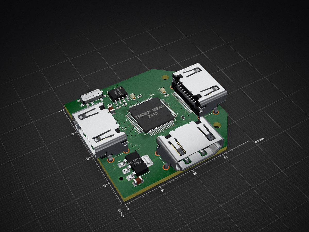
 Az154za/HDMA_DUAL_SWITCHER
HDMI SWITCH is an open-source printed circuit board by Az154za, from the Az154za/HDMA_DUAL_SWITCHER repository on GitHub. It is a 4-layer board of 39 × 37 mm with 20 parts on 61 nets, routed with 473 tracks and 80 vias.
It is built around the TMDS261BPAG, 24LC024/P and AMS1117-3.3. Its parts include 7 resistors, 3 ICs, 3 connectors, 2 capacitors and 2 diodes. It belongs with the interfaces and adapters boards of this library.


This is 2 to 1 hdmi multiplexer that can switch screen visualisation between two pcs with a switch toggle using the TMDS261BPAG
The PCB was 4 layers 1 layer for GND , one layer for 5V
#BOM :
| Qty | Value | Footprint | References |
|---|---|---|---|
| 3 | HDMI_A | Connector_Video:HDMI_A_Amphenol_10029449-x01xLF_Horizontal | J1, J2, J3 |
| 2 | 10uF | Capacitor_SMD:C_0805_2012Metric | C1, C2 |
| 2 | 330 | Resistor_SMD:R_0402_1005Metric | R6, R7 |
| 2 | 4.7k | Resistor_SMD:R_0402_1005Metric | R4, R5 |
| 2 | 47k | Resistor_SMD:R_0402_1005Metric | R1, R2 |
| 2 | LED | LED_SMD:LED_0603_1608Metric | D1, D2 |
| 2 | MountingHole | MountingHole:MountingHole_2.2mm_M2 | H2, H4 |
| 1 | 24LC02 | Package_SO:JEITA_SOIC-8_3.9x4.9mm_P1.27mm | U2 |
| 1 | 4.02k | Resistor_SMD:R_0402_1005Metric | R3 |
| 1 | AMS1117-3.3 | Package_TO_SOT_SMD:SOT-223-3_TabPin2 | U4 |
| 1 | SW_SPDT | Button_Switch_SMD:SW_SPDT_PCM12 | SW1 |
| 1 | TMDS261BPAG | TMDS261B:PAG64 | U1 |


embeddedboys/hdmi2rgb_adapter
hdmi2rgb_adapter is a simple HDMI to RGB deserializer based on TFP401 (TI)


gmarcus1018/Portfolio_Web
Personal portfolio site built with Astro. Static site, deploys to Cloudflare Pages.

joshajohnson/Hub20
Hub20 is a numpad with a bunch of features you never knew you needed.

It measures 39 × 37 mm and has 4 copper layers, 1.6 mm thick.
20 parts, built around the TMDS261BPAG, 24LC024/P and AMS1117-3.3. The full list of its parts is on this page, with links to each part's symbol and footprint where PCBKit's library has them.
From the Az154za/HDMA_DUAL_SWITCHER repository on GitHub, at the commit this page was made from: the board is PCB/HDMI_SWITCH.kicad_pcb and its schematic PCB/HDMI_SWITCH.kicad_sch. PCBKit opens the board in the browser, with nothing to install.
Its repository states no licence, so its author keeps all rights: ask Az154za before reusing the design.