Skip to the content
2 layers39 × 34 mmLM2576HV BREAKOUT MOD, the printed circuit board in 3D

LM2576HV switching regulator (12V) breakout board - Handle up to 60V input with high efficiency buck conversion. Open source hardware design.

Size
39 × 34 mm
Copper layers
2
Thickness
1.6 mm
Parts
13
Nets
4
Pads
30
Tracks, vias
0, 36
Pours
8
Routed
Not yet
KiCad
KiCad 8.0 (file 20240108)
Created
8 Nov 2025
Updated
21 Jan 2026

Overview

LM2576HV BREAKOUT MOD is an open-source printed circuit board by NatanaelBimo, from the NatanaelBimo/LM2576HV-BREAKOUT-MOD repository on GitHub. It is a 2-layer board of 39 × 34 mm with 13 parts on 4 nets.

It is built around the LM2576HVS-12. Its parts include 6 capacitors, 4 connectors, 1 IC, 1 diode and 1 inductor. It belongs with the power and interfaces and adapters boards of this library.

Main components

1

README

README.md

LM2576HV 12V Buck Converter Breakout Board (Up to 60V Input)

A compact LM2576HV step-down (buck) regulator breakout board configured for a fixed 12V output, designed for applications that require high-voltage DC input (up to 60V) and a robust 12V rail for embedded systems, relays, sensors, and automotive/industrial use.

Designed in KiCad and released as open-source hardware.


Preview
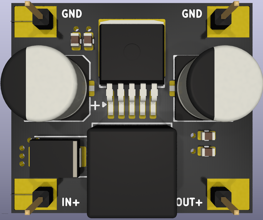
Board Preview


Key Features

  • Wide input range: up to 60V DC max (LM2576HV)
  • Fixed 12V output
  • Up to 3A output current (dependent on thermal design and input/output conditions)
  • Buck switching regulator (high efficiency)
  • TO-263-5 package for improved thermal performance
  • Input/output filtering capacitors
  • Mounting holes for mechanical stability

Specifications (Typical)

ParameterValue
Input voltage (VIN)12V – 60V DC
Output voltage (VOUT)12V fixed
Max output currentUp to 3A
Switching frequency~52kHz typical
Efficiencyup to ~90% (depends on load and VIN/VOUT)

Notes: Real output current capability strongly depends on PCB copper area, airflow, ambient temperature, and input/output capacitor selection.


Pinout / Connections

PinDescription
VINDC input (12–60V)
GNDGround
VOUTRegulated 12V output

Typical Use Cases

  • 48V/36V/24V → 12V rail for:
    • microcontrollers + peripherals
    • relays/solenoids (within current budget)
    • industrial sensors and instrumentation
    • automotive accessories (non-transient protected unless you add protection)

Design Notes / Engineering Considerations

Capacitor Ratings

  • Input capacitor must be rated above VIN
    • Recommended: ≥ 63V for high-voltage use
  • Output capacitor rating
    • Recommended: ≥ 25V

Thermal / Power

At high VIN and high load current, switching losses and thermal stress increase.

  • Provide copper area for heat spreading
  • Consider adding a heatsink or airflow at higher loads
  • Validate temperature rise during your target operating condition

Recommended Protection (External)

If used in harsh environments, consider adding:

  • Input fuse or polyfuse
  • Reverse polarity protection (MOSFET/diode)
  • TVS diode for surge/transient suppression

Repository Contents

  • LM2576HV-BREAKOUT-MOD.kicad_sch → schematic
  • LM2576HV-BREAKOUT-MOD.kicad_pcb → PCB layout
  • lm2576hv.pdf → reference datasheet
  • view.png → PCB preview

How to Manufacture (Quick Start)

  1. Open the .kicad_pro project in KiCad
  2. Run DRC/ERC
  3. Export:
    • Gerbers
    • Drill files
    • BOM
  4. Order PCB + assemble

Status

  • Prototype assembled and verified
  • Load testing completed
  • Thermal testing completed

License

MIT License.


References

Parts

13
QtyValueFootprintReferences
4Conn_01x01Connector_PinHeader_2.54mm:PinHeader_1x01_P2.54mm_VerticalJ1, J2, J3, J4
2.1uCapacitor_SMD:C_0805_2012MetricC3, C4
210uCapacitor_SMD:C_0805_2012MetricC2, C5
1330uInductor_SMD:L_SXN_SMDRI127L1
1>100uCapacitor_SMD:CP_Elec_10x10C1
1>3 ADiode_SMD:D_SMCD1
1>330uCapacitor_SMD:CP_Elec_10x10C6
1LM2576HVS-12Package_TO_SOT_SMD:TO-263-5_TabPin3U1

Similar boards

  • 4 layers77.8 × 47 mmDRIVER 8323 based, the printed circuit board in 3D

    DRIVER 8323 based

    M-K-O-Hybrid-open-source/Iskander

    Iskander is an open source driver for BLDC motors, the hardware support Six step commutation and FOC, still in the experimental phase but it will be ready as soon as possible

    72 parts12MIT
  • 2 layers120 × 100 mmOuttake controller 2026, the printed circuit board in 3D

    Outtake controller 2026

    Drexel-Robotics/LunaboticsElectrical2026

    For any embedded systems and PCB related projects.

    40 parts
  • 2 layers131.7 × 99.4 mmESP AUTOMATION, the printed circuit board in 3D

    ESP AUTOMATION

    gkhnmlym/ESP_AUTOMATION

    92 parts
  • 2 layers64.8 × 30.5 mmBuck, the printed circuit board in 3D

    Buck

    ibrahim-km/kicad-designs

    PCB designs created using KiCad, including power electronics and embedded hardware projects.

    8 parts
  • 4 layers250 × 126 mmBMS New PCB, the printed circuit board in 3D

    BMS New PCB

    sakshamgupta2004/VegapodAll

    All the vegapod material

    372 parts
  • 2 layers98.4 × 66 mmCarte Alim, the printed circuit board in 3D

    Carte Alim

    Pokibot-org/pokibot_elec

    36 partsApache-2.0

Questions

How big is the LM2576HV BREAKOUT MOD PCB?

It measures 39 × 34 mm and has 2 copper layers, 1.6 mm thick.

What parts does the LM2576HV BREAKOUT MOD use?

13 parts, built around the LM2576HVS-12. The full list of its parts is on this page, with links to each part's symbol and footprint where PCBKit's library has them.

Where can I download the LM2576HV BREAKOUT MOD KiCad files?

From the NatanaelBimo/LM2576HV-BREAKOUT-MOD repository on GitHub, at the commit this page was made from: the board is LM2576HV-BREAKOUT-MOD.kicad_pcb and its schematic LM2576HV-BREAKOUT-MOD.kicad_sch. PCBKit opens the board in the browser, with nothing to install.

Can I use the LM2576HV BREAKOUT MOD design in my own project?

Its repository states no licence, so its author keeps all rights: ask NatanaelBimo before reusing the design.