2 layers
IR2110
M-K-O-Hybrid-open-source/BUCK_manual_Process
the main aim of this design is the ease of the manual manufacturing process of this PCB and the availability of the component
43 parts

 M-K-O-Hybrid-open-source/Iskander12
Iskander is an open source driver for BLDC motors, the hardware support Six step commutation and FOC, still in the experimental phase but it will be ready as soon as possible
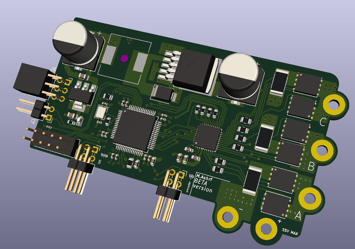
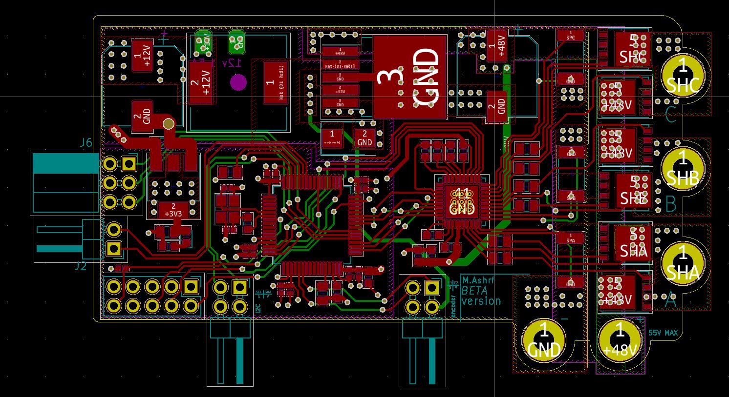
DRIVER 8323 based is an open-source printed circuit board by M-K-O-Hybrid-open-source, from the M-K-O-Hybrid-open-source/Iskander repository on GitHub, published under the MIT licence. It is a 4-layer board of 77.8 × 47 mm with 72 parts on 93 nets, routed with 683 tracks and 272 vias.
It is built around the LM2576HVS-12, AMS1117-3.3 and CSD19534Q5A, with the FR2M among its other parts. Its parts include 23 capacitors, 17 resistors, 13 connectors, 6 transistors and 4 ICs. It belongs with the robots and motor control boards and the STM32 boards of this library.


Iskander is an open source driver for low voltage DC, BLDC, PMSM motors, amde specifically for education and learning.
the repo containts some example ocodes and SIMULINK modeles to help you get started.
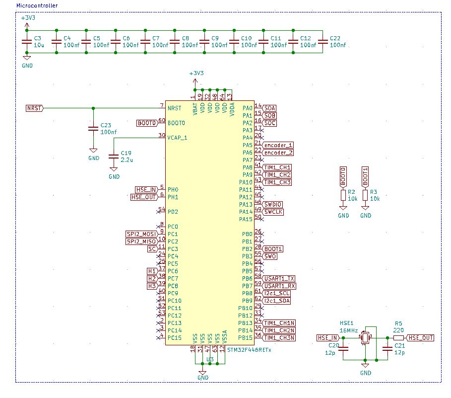
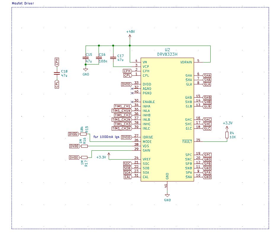
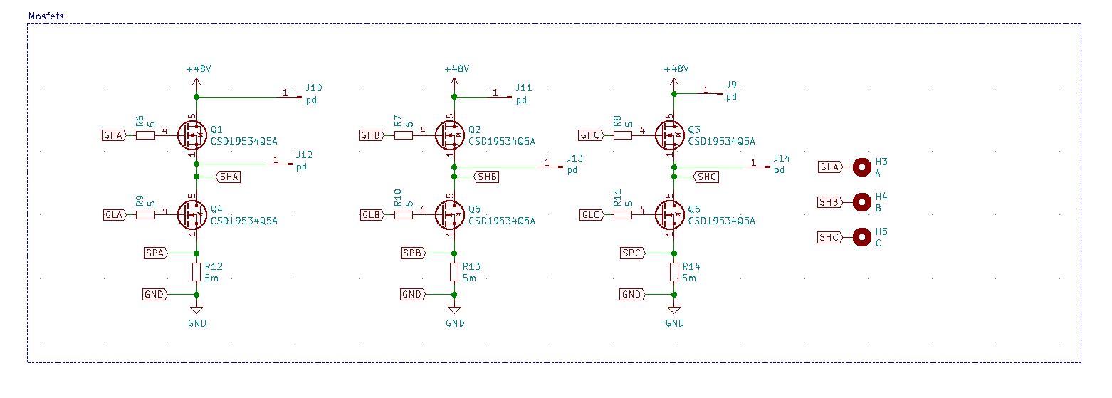
| Qty | Value | Footprint | References |
|---|---|---|---|
| 11 | 100nf | Capacitor_SMD:C_0402_1005Metric | C4, C5, C6, C7, C8, C9, C10, C11, C12, C22, C23 |
| 6 | 5 | Resistor_SMD:R_0805_2012Metric | R6, R7, R8, R9, R10, R11 |
| 6 | CSD19534Q5A | Package_TO_SOT_SMD:TDSON-8-1 | Q1, Q2, Q3, Q4, Q5, Q6 |
| 6 | pd | Connector_Wire:SolderWirePad_1x01_SMD_1x2mm | J9, J10, J11, J12, J13, J14 |
| 3 | 47u | Capacitor_SMD:C_0603_1608Metric | C15, C17, C18 |
| 3 | 5m | Resistor_SMD:R_2512_6332Metric | R12, R13, R14 |
| 2 | 10k | Resistor_SMD:R_0805_2012Metric | R2, R3 |
| 2 | 10u | Capacitor_SMD:C_0805_2012Metric | C1, C2 |
| 2 | 12p | Capacitor_SMD:C_0402_1005Metric | C20, C21 |
| 2 | 1M | Resistor_SMD:R_0603_1608Metric | R16, R17 |
| 1 | 1000u 25v | Capacitor_SMD:CP_Elec_10x10 | C14 |
| 1 | 100n | Capacitor_SMD:C_0603_1608Metric | C16 |
| 1 | 100u 100v | Capacitor_SMD:CP_Elec_10x10 | C13 |
| 1 | 10K | Resistor_SMD:R_0603_1608Metric | R4 |
| 1 | 10u | Capacitor_SMD:C_0603_1608Metric | C3 |
| 1 | 12v | Connector_Wire:SolderWirePad_1x01_SMD_1x2mm | J4 |
| 1 | 12vgnd | Connector_Wire:SolderWirePad_1x01_SMD_1x2mm | J7 |
| 1 | 16MHz | Crystal:Crystal_SMD_3225-4Pin_3.2x2.5mm | HSE1 |
| 1 | 18k | Resistor_SMD:R_0603_1608Metric | R15 |
| 1 | 1k | Resistor_SMD:R_0603_1608Metric | R1 |
| 1 | 2.2u | Capacitor_SMD:C_0603_1608Metric | C19 |
| 1 | 220 | Resistor_SMD:R_0603_1608Metric | R5 |
| 1 | 48v | MountingHole:MountingHole_2.7mm_Pad | H1 |
| 1 | 48vgnd | MountingHole:MountingHole_2.7mm_Pad | H2 |
| 1 | A | MountingHole:MountingHole_2.7mm_Pad | H3 |
| 1 | AMS1117-3.3 | Package_TO_SOT_SMD:SOT-223-3_TabPin2 | U1 |
| 1 | B | MountingHole:MountingHole_2.7mm_Pad | H4 |
| 1 | C | MountingHole:MountingHole_2.7mm_Pad | H5 |
| 1 | Conn_02x05_Odd_Even | Connector_PinHeader_2.54mm:PinHeader_2x05_P2.54mm_Vertical | J5 |
| 1 | DRV8323H | Package_DFN_QFN:QFN-40-1EP_6x6mm_P0.5mm_EP4.6x4.6mm_ThermalVias | U2 |
| 1 | FR2M | Diode_SMD:D_SMB | D1 |
| 1 | Hall_EFF | Connector_PinSocket_2.54mm:PinSocket_2x03_P2.54mm_Horizontal | J6 |
| 1 | I2C | Connector_PinHeader_2.54mm:PinHeader_2x02_P2.54mm_Horizontal | J3 |
| 1 | LM2576HVS-12 | Package_TO_SOT_SMD:TO-263-5_TabPin3 | U4 |
| 1 | Red | LED_SMD:LED_0603_1608Metric | D2 |
| 1 | STM32F446RETx | Package_QFP:LQFP-64_10x10mm_P0.5mm | U3 |
| 1 | SWRB120 | Inductor_SMD:L_12x12mm_H4.5mm | L1 |
| 1 | USART | Connector_PinHeader_2.54mm:PinHeader_1x02_P2.54mm_Horizontal | J2 |
| 1 | encoder | Connector_PinHeader_2.54mm:PinHeader_2x02_P2.54mm_Horizontal | J1 |
M-K-O-Hybrid-open-source/BUCK_manual_Process
the main aim of this design is the ease of the manual manufacturing process of this PCB and the availability of the component


Drexel-Robotics/LunaboticsElectrical2026
For any embedded systems and PCB related projects.

ibrahim-km/kicad-designs
PCB designs created using KiCad, including power electronics and embedded hardware projects.

NatanaelBimo/LM2576HV-BREAKOUT-MOD
LM2576HV switching regulator (12V) breakout board - Handle up to 60V input with high efficiency buck conversion. Open source hardware design.


It measures 77.8 × 47 mm and has 4 copper layers, 1.6 mm thick.
72 parts, built around the LM2576HVS-12, AMS1117-3.3, CSD19534Q5A and FR2M. The full list of its parts is on this page, with links to each part's symbol and footprint where PCBKit's library has them.
From the M-K-O-Hybrid-open-source/Iskander repository on GitHub, at the commit this page was made from: the board is Kicad_files/DRIVER_8323_based.kicad_pcb. PCBKit opens the board in the browser, with nothing to install.
Its repository publishes it under the MIT licence: you may reuse it on that licence's terms (keep the author's notice, and for a copyleft licence share your changes alike).