4 layers48 × 44.5 mm
Smol servo rpi2350-tmc6200
dognotdog/smol_servo
circuitry and software for controlling NEMA17 size brushless motors and stepper motors as servos.
151 parts5
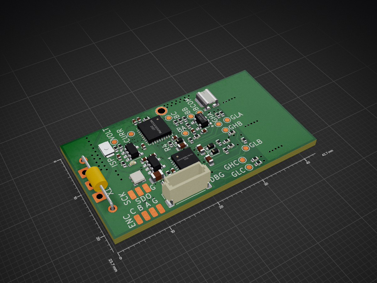
 NXP-Robotics/MR-ESC-AM329
Open Drone hardware design using NXP MCXA MCU running AM32 software - KiCAD
MR ESC MCXA AM32 is an open-source printed circuit board by NXP-Robotics, from the NXP-Robotics/MR-ESC-AM32 repository on GitHub. It is a 4-layer board of 42.7 × 23.7 mm with 97 parts on 66 nets, routed with 491 tracks and 128 vias.
It is built around the BB-2020BGR-TRB, MCXA133VFM and 1N4148WT. Its parts include 25 capacitors, 25 resistors, 16 connectors, 6 ICs and 6 transistors. It belongs with the robots and motor control boards of this library.


MR-ESC-AM32 (AKA MR-ESC-MCXA-AM32) is a reference design Drone motor ESC (Electronic Speed Controller) motor controller, using NXP MCXA133 MCU and running the open-source AM32 software. Hardware is available at NXP.com/MR-ESC-AM32
[!NOTE] AM32 support for the MCXA133 has already been merged in mainline AM32: AM32 application and AM32 bootloader. Build target for MCXA133 in main application is "FRDM_A153" and "AM32_A153_BOOTLOADER_PB2" in bootloader.
Hex files can be downloaded from the official AM32 configurator: AM32 configurator downloads
AM32 Motor Control Application: AM32_FRDM_A153_x.xx.hex; AM32 Bootloader: AM32_A153_BOOTLOADER_PB2_Vxx.hexFlash board using the 6-pin JST-SH connector (Pixhawk Debug Mini) Do note that when flashing with MCU-LINK, pin 3 should be removed.
Design files are made with KiCAD.
[!IMPORTANT] This design is not currently supported by NXP motor control framework tools (it could of course be made to run with modifications)
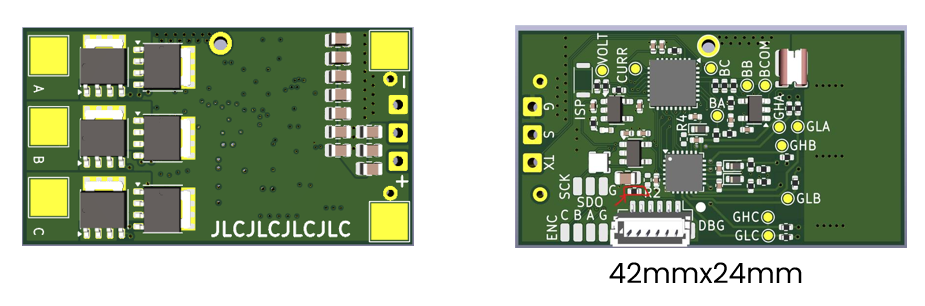
All pin data below comes from the KiCad design files in this repository.
Each card shows, per pin, the function, the net name in the schematic and the MCU pad the signal ends up on. Most connections are solder pads; the only connector is the debug port.

Not visible here: PWR BATTERY (bottom view) · MOTOR PHASES (bottom view)
Bottom side, with the battery and motor pads:

| Ref | Function | Connector | Details |
|---|---|---|---|
| ESC ENC ENCODER | Spare MCU pins for a quadrature encoder, solder pads | Four pads marked A, B, I and G, 3.3 V logic | |
| ESC MOTOR PHASES | Three motor phase outputs | Three solder pads on the bottom side, marked A, B and C | |
| ESC PWR BATTERY | Battery input, 6 to 24 V (2S to 6S LiPo) | Two solder pads on the bottom side, marked + and - | |
| ESC RC SIGNAL | Throttle input and telemetry output, solder pads | Three wire pads marked S, G and TX, 3.3 V logic | |
| ESC RGB LED CHAIN | Output of the on-board RGB LED chain, solder pads | Three pads marked SDO, SCK and G, 3.3 V logic | |
| ESC J13 DEBUG | SWD debug and console (DS-009 debug mini) | JST-SH 1x6 (BM06B-SRSS-TB) |

Solder the battery leads here. Input range is 6 to 24 V, so 2S to 6S LiPo. The 5 V and 3.3 V rails come from two TPS7B92 linear regulators on this input; below about 6 V the 5 V rail drops out. All parts on the battery rail are rated 35 V or more (capacitors 35 V, regulators 40 V, FETs 80 V), which leaves margin for a full 6S pack at 25.2 V. Keep the 470 µF capacitor across the pads when you use long battery leads.
[!CAUTION] There is no reverse polarity protection. Check + and - before you connect a battery.

Each phase is a half bridge of two PSMN3R3-80 FETs (80 V), driven by the gate driver U2. Swap any two phases to reverse the motor direction. The phase voltages also feed the back-EMF comparators of the MCU, which is how the ESC senses the rotor position.

S is the throttle signal from the flight controller. The AM32 port for this MCU detects the input type by itself and supports DShot300, DShot600 (both also as bidirectional DShot) and normal servo PWM (1 to 2 ms, up to 400 Hz). DShot150 and other protocols are not supported. AM32 reads the signal with a CTIMER0 capture input and, for bidirectional DShot, switches the same pin to LPSPI0 to send the RPM telemetry back on the signal wire. TX is the AM32 serial telemetry output on LPUART1, 115200 baud, for a flight controller ESC telemetry input.
[!NOTE] The signal input is 3.3 V logic. Do not connect it to a 5 V PWM source without a level shifter.

Flash and debug the MCU over SWD with any probe that supports the DS-009 debug mini cable. Pins 2 and 3 are LPUART0 on the MCU, free for a console; AM32 sends its telemetry on LPUART1 (the TX pad) instead. Pin 1 is a 3.3 V reference output for the probe.
[!WARNING] Pin 1 is a reference output, not a supply input. Never power the board from it.
[!IMPORTANT] Pin 3 should be removed when debugging with an MCU-LINK.

Prepared for an encoder on wheeled robots, where the ESC needs odometry. The AM32 firmware does not use them yet; it only drives A and I as debug outputs. Nothing else on the board is connected to these pins.

The MCU drives one APA102-type RGB LED (U5) on LPSPI1. These pads are the data and clock outputs of that LED, so more LEDs of the same type can be chained from here.
Thirteen round pads on the top side, named on the silkscreen. They are probe points for a scope or meter, not for wires.
| Pad | Net | MCU pin | What you see there |
|---|---|---|---|
| GHA, GHB, GHC | GHA, GHB, GHC | P3_1, P3_9, P3_11 drive them | Gate of the high side FET of phase A, B, C. Output of the gate driver U2. |
| GLA, GLB, GLC | GLA, GLB, GLC | P3_0, P3_8, P3_10 drive them | Gate of the low side FET of phase A, B, C. Output of the gate driver U2. |
| BA, BB, BC | BEMFA, BEMFB, BEMFC | P1_0, P1_1, P1_3 | Back-EMF of phase A, B, C, scaled down by a divider. The MCU comparator uses these to find the rotor position. |
| BCOM | BEMF_COMMON | P2_2, P2_3 | Virtual star point: the three phase dividers joined. Reference for the back-EMF comparator. |
| VOLT | VOLTSENSE | P2_16 (ADC0 channel 6) | Battery voltage, scaled down by a divider. |
| CURR | CURRENT | P2_7 (ADC0 channel 7) | Output of the INA180 current amplifier: motor current as a voltage. |
| GND | GND | Ground for the probe. |
| Ref | Board | Function | Type | Notes |
|---|---|---|---|---|
| SW1 ISP | ESC | ISP boot button | Tactile switch | Hold it while power comes up to start the MCU boot ROM in ISP mode (P3_29 pulled low). Normal boot otherwise. |
The board runs the open AM32 firmware. The firmware fork for this MCU, the hex files and how to flash them are in the MR-ESC-MCXA-AM32 README.
Settings are changed with the AM32 web configurator over the signal wire, pad S. Connect it either through the flight controller (Betaflight passthrough) or with a serial link to a PC. No extra connector is needed. The input protocols the firmware accepts are listed on the RC SIGNAL card.
Useful pages on the AM32 wiki:
[!TIP] AM32 beeps through the motor at power up and after a settings change. Connect a motor before you look for the beep codes.
[!WARNING] The board has no reverse polarity protection and no input fuse. Wrong polarity on the battery pads destroys it.
This reference as an A4 PDF, and all cards on one A4 landscape sheet: cheat sheet PDF.
NXP and the NXP logo are registered trademarks of NXP B.V. This document is maintained by the community and is not an official NXP publication.
| Qty | Value | Footprint | References |
|---|---|---|---|
| 11 | 10uF 35V | Capacitor_SMD:C_0805_2012Metric | C1, C2, C3, C4, C5, C6, C7, C8, C9, C10, C15 |
| 8 | 10k | Resistor_SMD:R_0402_1005Metric | R1, R3, R8, R9, R10, R11, R12, R13 |
| 6 | 20 | Resistor_SMD:R_0402_1005Metric | R5, R6, R7, R17, R18, R19 |
| 6 | PSMN3R3-80YSFX | Package_TO_SOT_SMD:LFPAK56 | Q1, Q2, Q3, Q4, Q5, Q6 |
| 5 | 100nF 16V | Capacitor_SMD:C_0402_1005Metric | C13, C14, C16, C24, C25 |
| 4 | 1k | Resistor_SMD:R_0402_1005Metric | R14, R15, R16, R22 |
| 3 | 1N4148WT | Diode_SMD:D_SOD-523 | D1, D2, D3 |
| 3 | 1uF 10V | Capacitor_SMD:C_0402_1005Metric | C12, C19, C23 |
| 3 | 1uF 50V | Capacitor_SMD:C_0603_1608Metric | C17, C20, C21 |
| 2 | 100nF 50V | Capacitor_SMD:C_0402_1005Metric | C18, C22 |
| 2 | GND | Connector_Wire:SolderWirePad_1x01_SMD_1x2mm | J12, J16 |
| 1 | 0R | Resistor_SMD:R_0402_1005Metric | R2 |
| 1 | 100R | Resistor_SMD:R_0402_1005Metric | R25 |
| 1 | 100k | Resistor_SMD:R_0402_1005Metric | R4 |
| 1 | 100k 0.1% | Resistor_SMD:R_0402_1005Metric | R20 |
| 1 | 10k 0.1% | Resistor_SMD:R_0402_1005Metric | R24 |
| 1 | 1m 3W | Current_sense_resistor:WSK1216 | R21 |
| 1 | 2.2k | Resistor_SMD:R_0402_1005Metric | R23 |
| 1 | 470uF 35V | Capacitor_THT:C_Axial_L3.8mm_D2.6mm_P12.50mm_Horizontal | C11 |
| 1 | BB-2020BGR-TRB | RGB_LED:BB-2020BGR-TRB | U5 |
| 1 | BEMFA | TestPoint:TestPoint_Pad_D1.0mm | TP5 |
| 1 | BEMFB | TestPoint:TestPoint_Pad_D1.0mm | TP6 |
| 1 | BEMFC | TestPoint:TestPoint_Pad_D1.0mm | TP7 |
| 1 | BEMF_COMMON | TestPoint:TestPoint_Pad_D1.0mm | TP1 |
| 1 | CURRENT | TestPoint:TestPoint_Pad_D1.0mm | TP11 |
| 1 | DEBUG | Connector_JST:JST_SH_BM06B-SRSS-TB_1x06-1MP_P1.00mm_Vertical | J13 |
| 1 | DRV8300N or FD6288 or equivalent | Package_DFN_QFN:VQFN-24-1EP_4x4mm_P0.5mm_EP2.45x2.45mm | U2 |
| 1 | ENC_A | Connector_Wire:SolderWirePad_1x01_SMD_1x2mm | J9 |
| 1 | ENC_B | Connector_Wire:SolderWirePad_1x01_SMD_1x2mm | J10 |
| 1 | ENC_I | Connector_Wire:SolderWirePad_1x01_SMD_1x2mm | J11 |
| 1 | GHA | TestPoint:TestPoint_Pad_D1.0mm | TP2 |
| 1 | GHB | TestPoint:TestPoint_Pad_D1.0mm | TP3 |
| 1 | GHC | TestPoint:TestPoint_Pad_D1.0mm | TP4 |
| 1 | GLA | TestPoint:TestPoint_Pad_D1.0mm | TP8 |
| 1 | GLB | TestPoint:TestPoint_Pad_D1.0mm | TP9 |
| 1 | GLC | TestPoint:TestPoint_Pad_D1.0mm | TP10 |
| 1 | GND | TestPoint:TestPoint_THTPad_D2.0mm_Drill1.0mm | TP13 |
| 1 | GND | Connector_Wire:SolderWire-0.5sqmm_1x01_D0.9mm_OD2.1mm | J8 |
| 1 | INA180B1 | Package_TO_SOT_SMD:SOT-23-5 | U6 |
| 1 | ISPMODE | Switches:TS2306A | SW1 |
| 1 | LED GREEN | LED_SMD:LED_0402_1005Metric | D4 |
| 1 | LOGO | LOGO | G*** |
| 1 | MCXA133VFM | Package_DFN_QFN:HVQFN-32-1EP_5x5mm_P0.5mm_EP3.1x3.1mm | U3 |
| 1 | MOTORA | TestPoint:TestPoint_Pad_4.0x4.0mm | J17 |
| 1 | MOTORB | TestPoint:TestPoint_Pad_4.0x4.0mm | J18 |
| 1 | MOTORC | TestPoint:TestPoint_Pad_4.0x4.0mm | J19 |
| 1 | SIGNAL_INPUT | Connector_Wire:SolderWire-0.5sqmm_1x01_D0.9mm_OD2.1mm | J7 |
| 1 | SPI_SCK | Connector_Wire:SolderWirePad_1x01_SMD_1x2mm | J15 |
| 1 | SPI_SDO | Connector_Wire:SolderWirePad_1x01_SMD_1x2mm | J14 |
| 1 | TPS7B92033DBVR | Package_TO_SOT_SMD:SOT-23-5 | U1 |
| 1 | TPS7B92050DBVR | Package_TO_SOT_SMD:SOT-23-5 | U4 |
| 1 | TX | Connector_Wire:SolderWire-0.5sqmm_1x01_D0.9mm_OD2.1mm | J6 |
| 1 | V+ | TestPoint:TestPoint_Pad_4.0x4.0mm | J1 |
| 1 | V- | TestPoint:TestPoint_Pad_4.0x4.0mm | J2 |
| 1 | VOLTSENSE | TestPoint:TestPoint_Pad_D1.0mm | TP12 |
dognotdog/smol_servo
circuitry and software for controlling NEMA17 size brushless motors and stepper motors as servos.

agausmann/riemann-kb-pre1
Riemann: A 60% pseudo-split ortholinear keyboard.


shanteacontrols/OpenDeck
A platform for building interactive control and sensing devices using MIDI and OSC built with Zephyr RTOS.

beekeeb/zerosprey42
Zerosprey42 Keyboard is a wired, beginner friendly, choc hotswap, MonoBlockSplit (Unibody), column-staggered, DIY mechanical keyboard.


todbot/macropadsynthplug
Turn StemmaQT port by into Audio Out + MIDI In

acha666/RP2040_ToolheadPCB_SB
A Toolhead PCB for VORON StealthBurner based on RP2040
It measures 42.7 × 23.7 mm and has 4 copper layers, 1.6 mm thick.
97 parts, built around the BB-2020BGR-TRB, MCXA133VFM and 1N4148WT. The full list of its parts is on this page, with links to each part's symbol and footprint where PCBKit's library has them.
From the NXP-Robotics/MR-ESC-AM32 repository on GitHub, at the commit this page was made from: the board is MR-ESC-MCXA-AM32.kicad_pcb and its schematic MR-ESC-MCXA-AM32.kicad_sch. PCBKit opens the board in the browser, with nothing to install.
Its repository states no licence, so its author keeps all rights: ask NXP-Robotics before reusing the design.