4 layers19 × 51 mm
MorseCommunicator
zeankundev/boards
A collection and an archive of KiCad projects I made. Contains projects from 2023 - 2024.
56 parts1
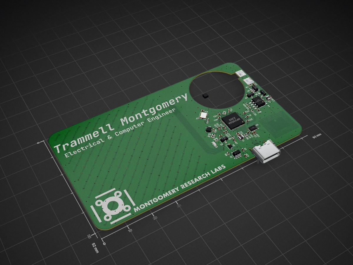
 MontgomeryResearchLabs/C.A.R.D.
Connection And Resuable Device
JT Business Card is an open-source printed circuit board by MontgomeryResearchLabs, from the MontgomeryResearchLabs/C.A.R.D. repository on GitHub, published under the MIT licence. It is a 2-layer board of 93 × 52 mm with 527 parts on 91 nets, routed with 2,207 tracks and 391 vias.
It is built around the RP2350A, ZD25WQ32CEIGR and DW01A, with the ST25DV04KC-IE6S3, 150060GS75000 and ABM8-272-T3 among its other parts. Its parts include 443 diodes, 38 resistors, 26 capacitors, 6 ICs and 2 transistors. It belongs with the RP2350 boards of this library.


A 3D hardware-in-the-loop simulator for an RP2350 business card that was never fabricated.
S.I.M. runs the card's real Pico SDK C firmware, unmodified, against an electrical model of the circuit built straight from its KiCad files, and shows the result on a 3D card you can tilt. It answers the question a first prototype would have answered: does this firmware drive this hardware correctly?
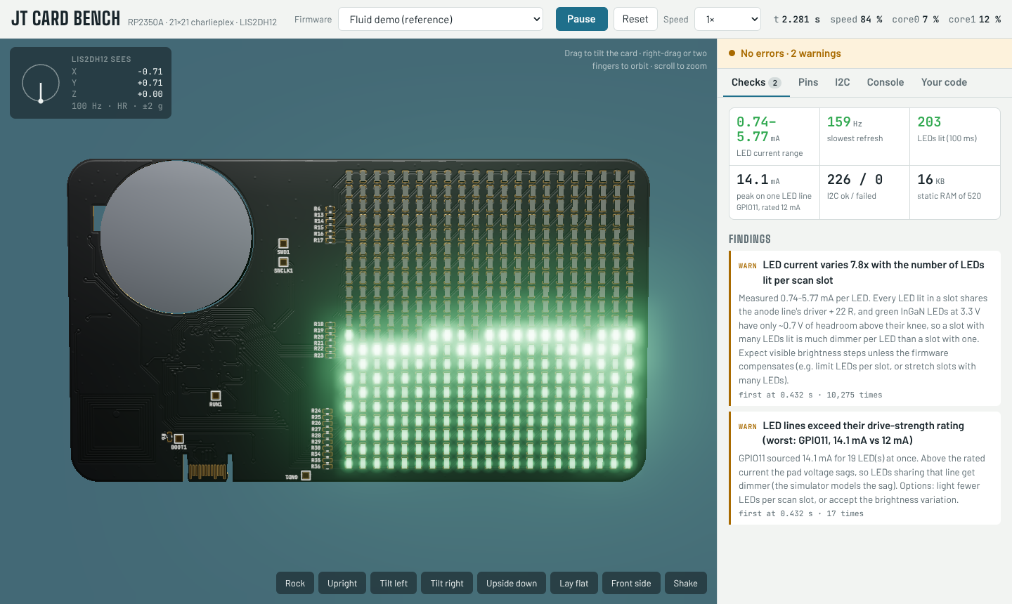
The board: an RP2350A, a 21×21 charlieplexed matrix of 441 green 0603 LEDs on 22 GPIOs, a LIS2DH12 accelerometer, an ST25DV04K NFC tag and a coin cell. The reference firmware is a particle fluid that flows as you tilt the card.
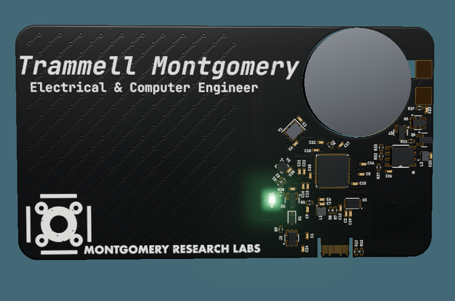
docs/index.html,
or this repository's GitHub Pages site if it is enabled (Settings → Pages →
branch main, folder /docs). Drag the card to tilt it; right-drag to orbit.Requirements: Node.js 18+, Python 3, and clang + wasm-ld (LLVM 15 or newer).
npm install                       # Binaryen, three.js, esbuild

# macOS: Apple's clang has no WebAssembly target, so use Homebrew's LLVM
brew install llvm lld
export PATH="$(brew --prefix llvm)/bin:$(brew --prefix lld)/bin:$PATH"
# Ubuntu / Debian:  sudo apt install clang lld

npm run build                     # compile the reference firmware to .wasm
npm test                          # run it headless and print a report
node tools/sim.mjs firmware/fluid-demo # compile and open the 3D view| Task | Command |
|---|---|
| Compile a firmware folder and open it in 3D | node tools/sim.mjs path/to/firmware |
Open a .wasm you already built | node tools/sim.mjs fw.wasm |
| Compile only | node tools/build-firmware.mjs path/to/firmware -o fw.wasm |
| Text report, for scripts and CI | node tools/run-headless.mjs fw.wasm (exit 0 = no errors, 1 = errors, 2 = firmware stopped) |
Rebuild the page in docs/ | npm run pages |
The same firmware also builds for the real chip with the Pico SDK; see
firmware/fluid-demo/CMakeLists.txt.
 .kicad_pcb ──┬─ kicad_pcb_extract.py ─▶ board.json ───────┐
              │                         led_map.h ─▶ firmware
              └─ kicad_artwork.py ────▶ artwork.json ─┐    │
                                                      │    ▼
 firmware C ──── build-firmware.mjs ──▶ firmware.wasm ─▶ engine.js ── board.js ── devices.js
                 clang → cycle counter → asyncify     │   (2 cores,    (pins,      (LIS2DH12,
                                                      │    virtual      LED solve,   ST25DV)
                                                      ▼    time, IRQs)  I2C checks)
                                          3D page (three.js)   or   run-headless.mjs
Reading the design files. A dependency-free Python S-expression parser reads
the .kicad_pcb. It finds the 22 GPIO lines through the series resistors
between Net-(U1-GPIOn) and /LED_ARRAY/Dk nets, finds every LED with both pads
on LED nets, uses the pads' A/K pin functions to tell anode from cathode, and
clusters positions into the 21×21 grid. A second script extracts the visual
layers: Edge.Cuts chained into the outline and cutouts, copper, mask openings, and
silkscreen. Silkscreen text comes from the polygons KiCad caches for outline fonts,
so it renders exactly.
Running the firmware. The firmware is compiled with clang to WebAssembly against a simulated Pico SDK: 22 headers with the real SDK's names and signatures, implemented on about 30 JavaScript imports. Calling an unsupported SDK function fails at link time with its name. A Binaryen pass adds a Cortex-M33 instruction-cost counter, so compute time is deterministic. Binaryen's asyncify pass lets the engine suspend and resume each core at any SDK call, which gives two cores with their own stacks and virtual clocks, kept within 5 µs of each other, plus timers, alarms and GPIO interrupts on core 0.
The electrical model. Every pin change re-solves the charlieplex matrix. Each driven line is a source behind the pad resistance plus the 22 Ω resistor, and each conducting LED is a 2.55 V knee plus 32 Ω. Kirchhoff's current law gives a small linear system, solved directly. Current is added over time per LED, which becomes brightness and refresh rate. The model also flags pins over their drive rating, leakage glow through pull resistors, shorts, and outputs fighting other chips.
Peripherals. I2C transactions succeed only if the bus would really work: the pins are routed, and the pull-ups (powered from GPIO29 on this board) are on. A register-level LIS2DH12 model samples gravity from the 3D card's orientation, rotated into the sensor's axes using its footprint pose in the PCB.
A longer write-up of each part is in docs/HOW-IT-WORKS.md.
| Finding | Consequence |
|---|---|
| LED current varies 7.8× (0.74–5.77 mA) with the number of LEDs lit in a scan slot | A full pool looks patchy. Green InGaN at 3.3 V leaves ~0.7 V for the driver and 22 Ω resistor |
| An anode line peaks at 14.1 mA against a 12 mA drive rating | Voltage sag, adding to the dimming |
| GPIO26/27/28 have no-connect flags but are wired to GND | Driving one high is a short |
| The I2C pull-ups are powered from GPIO29, not 3V3 | Nothing answers on I2C until firmware drives GPIO29 high |
| The LIS2DH12 is rotated −45° and on the opposite side from the LEDs | Firmware must rotate and mirror its axes |
Most of the code knows nothing about this card. The parts to adapt:
| To change | Where |
|---|---|
| How the board looks in 3D | Nothing: run tools/kicad_artwork.py on any KiCad 7–9 board |
| How LEDs and GPIOs are found | Net-name patterns and the accelerometer reference in tools/kicad_pcb_extract.py |
| LED drive topology | solve() in sim/core/board.js (any charlieplex works as is) |
| Component values | ELEC at the top of sim/core/board.js |
| Board-specific hazards | checkHazards() and I2CBus.checkBus() in sim/core/board.js |
| I2C chips | A class with start / write / read / stop in sim/core/devices.js, registered in engine.js |
| More SDK functions | Header in sim/hal/include, C in sim/hal/src/hal.c, an import in sim_imports.h and makeImports() |
| Another MCU or SDK | New headers in sim/hal/; the compiler pipeline, scheduler and board model are unchanged |
Keep a deliberately broken firmware next to the real one, like
firmware/examples/common-mistakes.
If the simulator does not catch the bugs you planted, it will not catch the ones
you did not plan.
After a PCB change:
python3 tools/kicad_pcb_extract.py board/JT-Business-Card.kicad_pcb \
    -o board/board.json --header firmware/fluid-demo/led_map.h
python3 tools/kicad_artwork.py board/JT-Business-Card.kicad_pcb -o board/artwork.json
npm run build && npm run pagessio_hw->…), PIO, DMA, PWM, ADC, USB and flash writes are not simulated.tight_loop_contents().| Path | Contents |
|---|---|
board/ | The card's KiCad PCB and schematic, plus the extracted board.json and artwork.json |
firmware/fluid-demo/ | Reference firmware: charlieplex scan driver, LIS2DH12 driver, particle fluid |
firmware/examples/common-mistakes/ | Firmware that is wrong on purpose, to show each check firing |
sim/hal/ | The simulated Pico SDK |
sim/core/ | Engine (engine.js), electrical model (board.js), I2C devices (devices.js) |
sim/web/ | The 3D page: scene, artwork painter, UI |
tools/ | Extractors, firmware build, cycle counter, page build, headless runner, launcher |
docs/ | The built simulator page (for GitHub Pages) and screenshots |
MIT.
| Qty | Value | Footprint | References |
|---|---|---|---|
| 441 | LED | user_footprints:LED_0603_1608Metric | D101, D102, D103, D104, D105, D106, D107, D108, D109, D110, D111, D112, D113, D114, D115, D116 +425 |
| 22 | 22 | Resistor_SMD:R_0402_1005Metric | R13, R14, R15, R16, R17, R18, R19, R20, R21, R22, R23, R24, R25, R26, R27, R28 +6 |
| 15 | 100n | user_footprints:C_0402_1005Metric_small_pads | C2, C8, C11, C12, C13, C14, C15, C16, C17, C18, C20, C21, C23, C25, C26 |
| 5 | TestPoint | TestPoint:TestPoint_Pad_1.0x1.0mm | BOOT1, GND1, RUN1, SWCLK1, SWD1 |
| 4 | 4.7u | user_footprints:C_0402_1005Metric_small_pads | C6, C7, C9, C10 |
| 4 | 5K1 | Resistor_SMD:R_0402_1005Metric | R1, R3, R11, R12 |
| 3 | 1K | Resistor_SMD:R_0402_1005Metric | R2, R6, R31 |
| 3 | 1u | user_footprints:C_0402_1005Metric_small_pads | C1, C5, C24 |
| 2 | 0 | Resistor_SMD:R_0402_1005Metric | R32, R33 |
| 2 | 10u | user_footprints:C_0402_1005Metric_small_pads | C19, C22 |
| 2 | 15p | user_footprints:C_0402_1005Metric_small_pads | C3, C4 |
| 2 | 27 | Resistor_SMD:R_0402_1005Metric | R7, R8 |
| 2 | 3.3u | RP2350_60QFN_minimal:L_pol_2016 | L1, L3 |
| 2 | HL-2302V | Package_TO_SOT_SMD:SOT-23 | Q6, Q7 |
| 1 | 100 | Resistor_SMD:R_0402_1005Metric | R10 |
| 1 | 10K | Resistor_SMD:R_0402_1005Metric | R37 |
| 1 | 110 | Resistor_SMD:R_0402_1005Metric | R38 |
| 1 | 150060GS75000 | 150060GS7500:LED_0603_WRE | LED1 |
| 1 | 20K | Resistor_SMD:R_0402_1005Metric | R9 |
| 1 | 33 | Resistor_SMD:R_0402_1005Metric | R5 |
| 1 | ABM8-272-T3 | Crystal:Crystal_SMD_3225-4Pin_3.2x2.5mm | Y1 |
| 1 | Battery_Cell | user_footprints:BatteryHolder_Custom | BT1 |
| 1 | DW01A | Package_TO_SOT_SMD:SOT-23-6 | U5 |
| 1 | LIS2DH12TR | Package_LGA:LGA-12_2x2mm_P0.5mm | U4 |
| 1 | LOGO | LOGO | G*** |
| 1 | REG_3.3V | Package_TO_SOT_SMD:SOT-23 | U2 |
| 1 | RP2350A | RP2350_60QFN_minimal:RP2350-QFN-60-1EP_7x7_P0.4mm_EP3.4x3.4mm_ThermalVias | U1 |
| 1 | ST25DV04KC-IE6S3 | footprints:SO-8_STM | U6 |
| 1 | Schottky Diode | Diode_SMD:D_SOD-323 | D1 |
| 1 | TP4057 | Package_TO_SOT_SMD:SOT-23-6 | J3 |
| 1 | USB_C_Receptacle_USB2.0_14P | user_footprints:USB_C_PADDLE | J1 |
| 1 | ZD25WQ32CEIGR | Package_SON:Winbond_USON-8-1EP_3x2mm_P0.5mm_EP0.2x1.6mm | U3 |
zeankundev/boards
A collection and an archive of KiCad projects I made. Contains projects from 2023 - 2024.

RadianiteComputers/RadianiteBoards
A collection of Radianite boards we have designed so far. All are licensed under CC BY-SA 4.0


WOOWTECH/Woow_zigbee_fresh_air_pcb
WO_30109 Zigbee 新風控制器 PCB(KiCad 10,git 版控;V1.3 重繪 + V2.0 安規改版)
It measures 93 × 52 mm and has 2 copper layers, 0.6 mm thick.
527 parts, built around the RP2350A, ZD25WQ32CEIGR, DW01A and ST25DV04KC-IE6S3. The full list of its parts is on this page, with links to each part's symbol and footprint where PCBKit's library has them.
From the MontgomeryResearchLabs/C.A.R.D. repository on GitHub, at the commit this page was made from: the board is board/JT-Business-Card.kicad_pcb and its schematic board/JT-Business-Card.kicad_sch. PCBKit opens the board in the browser, with nothing to install.
Its repository publishes it under the MIT licence: you may reuse it on that licence's terms (keep the author's notice, and for a copyleft licence share your changes alike).