


2 layers85 × 105 mm

EE463 Term Project
HBridge is an open-source printed circuit board by Mehmet-Emre-Dogan, from the Mehmet-Emre-Dogan/EE463_2022_TermProject repository on GitHub. It is a 2-layer board of 216 × 121 mm with 27 parts on 35 nets, routed with 176 tracks and 2 vias.
It is built around the ROE-0512S and TLP250(F). Its parts include 8 resistors, 6 connectors, 4 ICs, 4 transistors and 1 capacitor.
2 kW Smart DC motor drive.
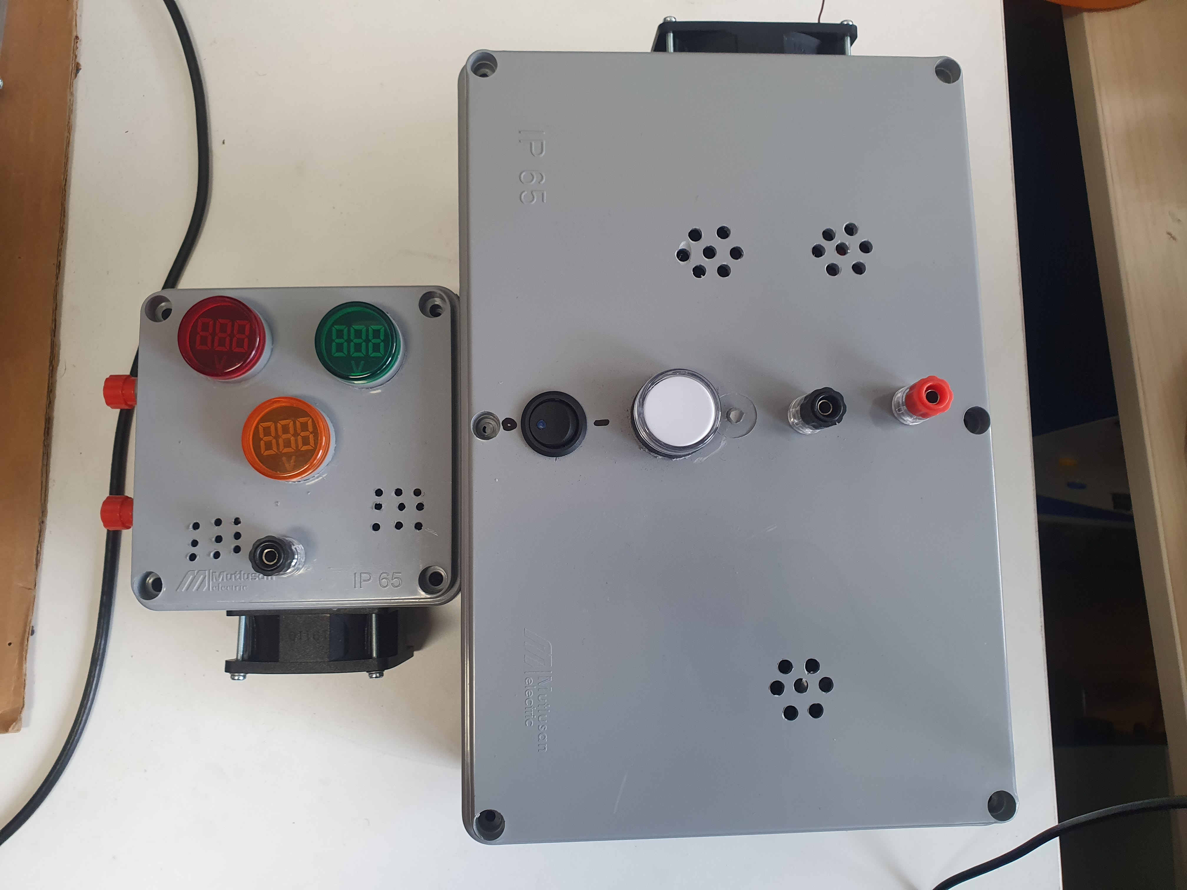
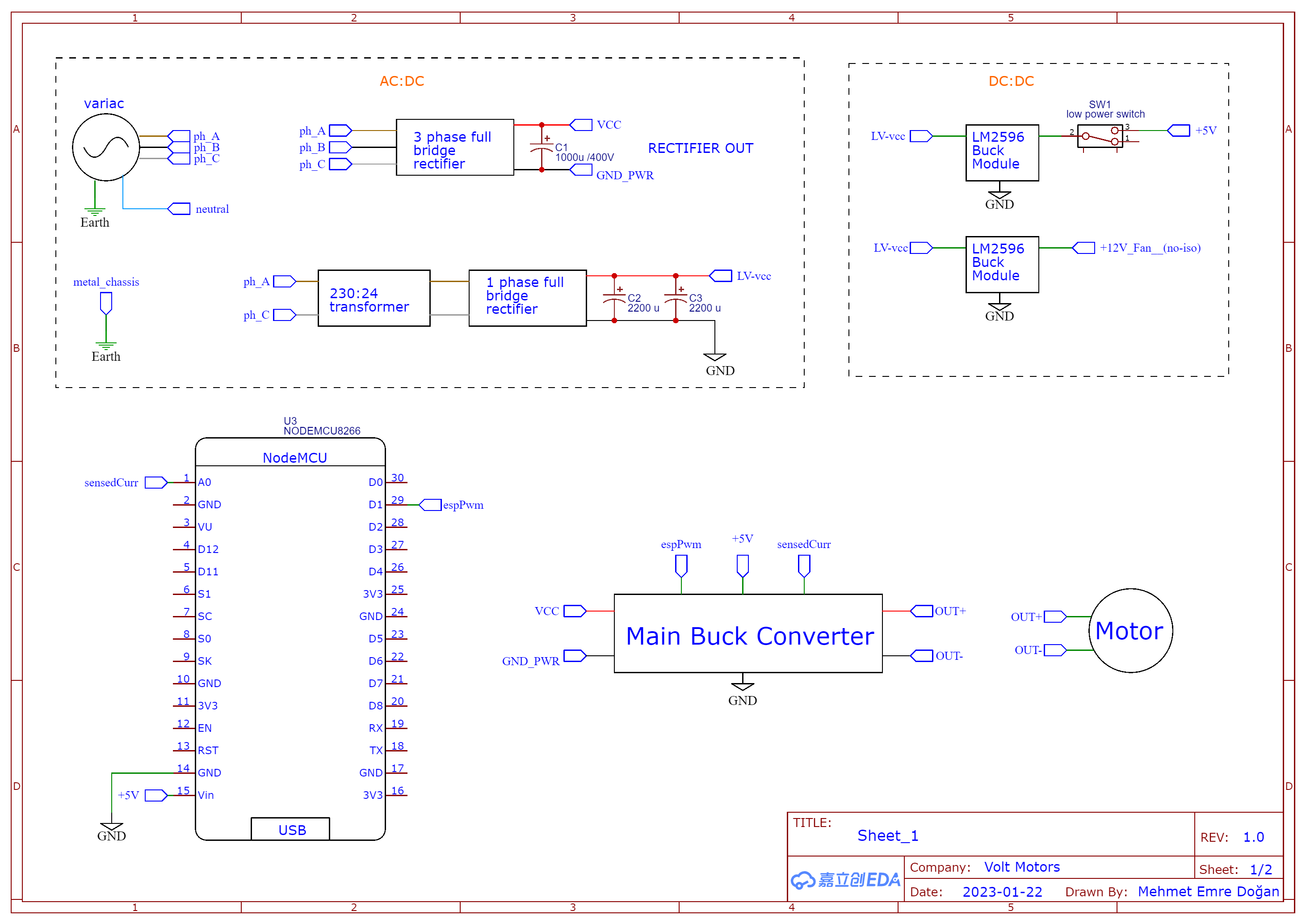
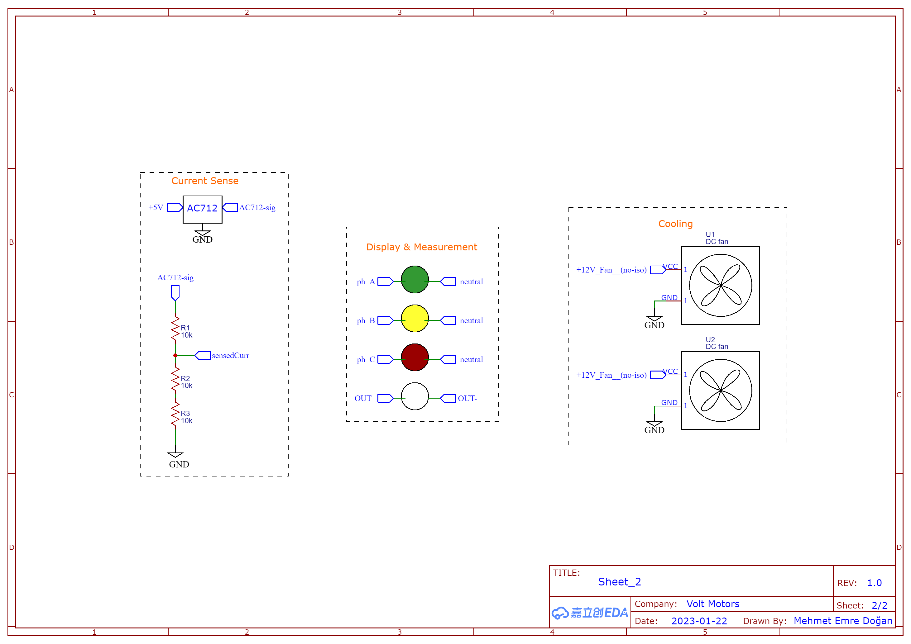
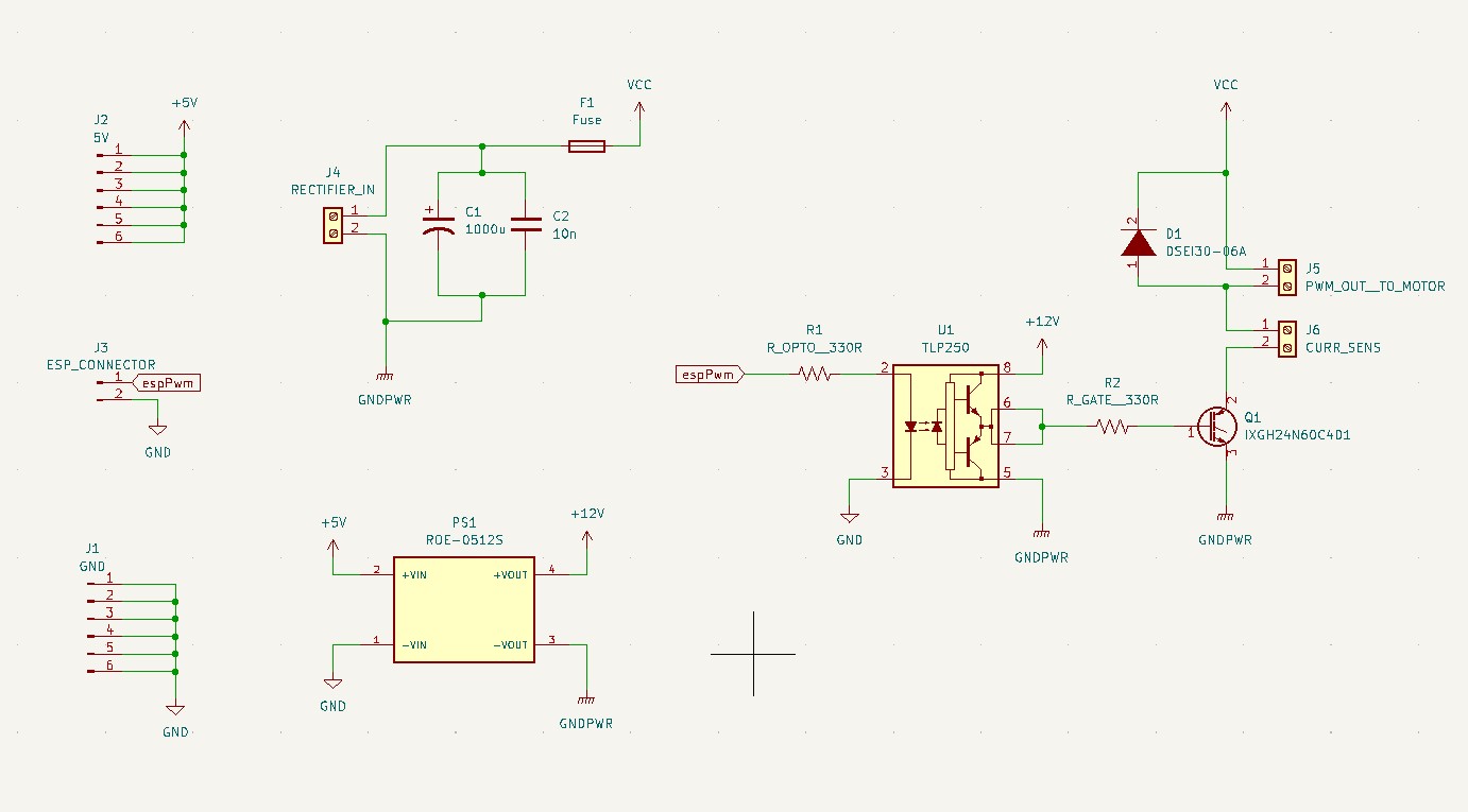
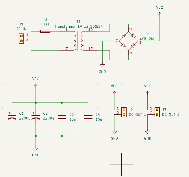
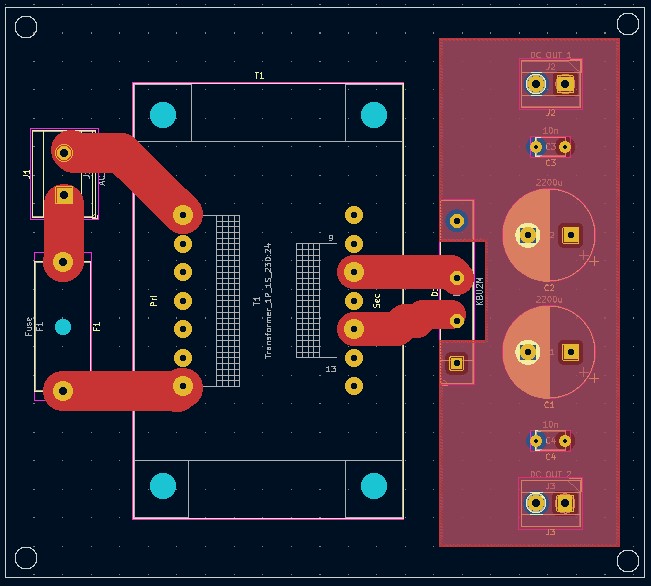
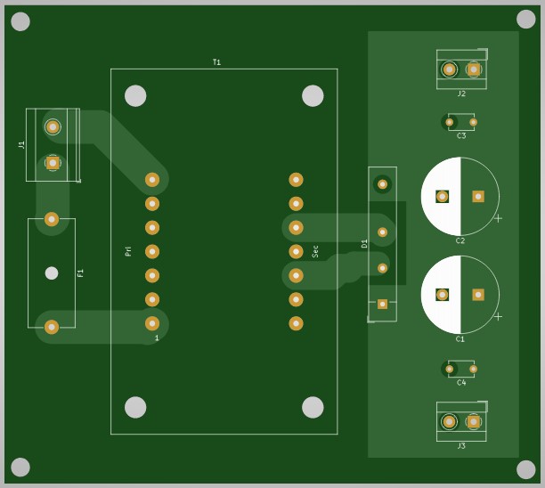
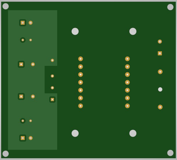
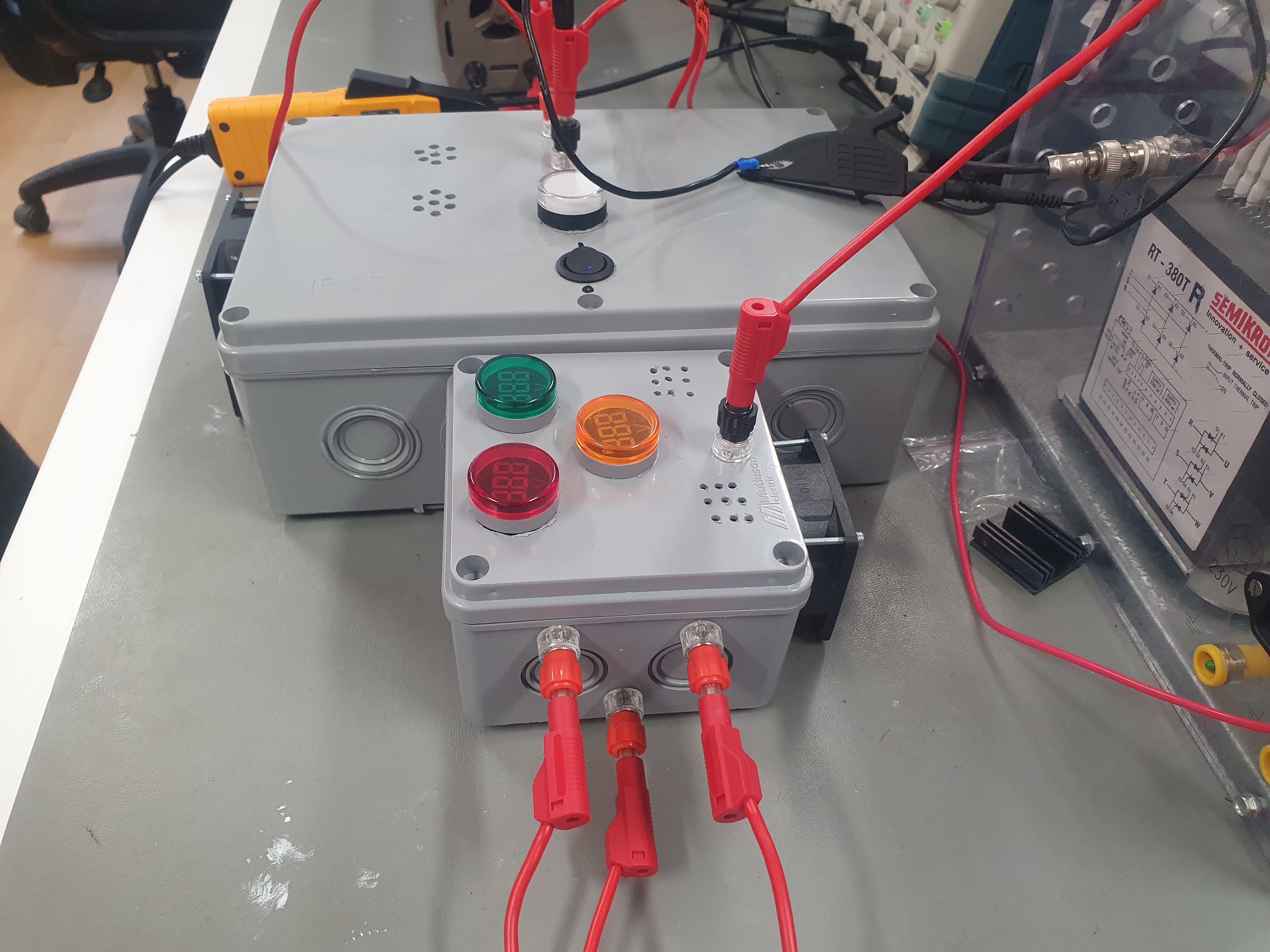
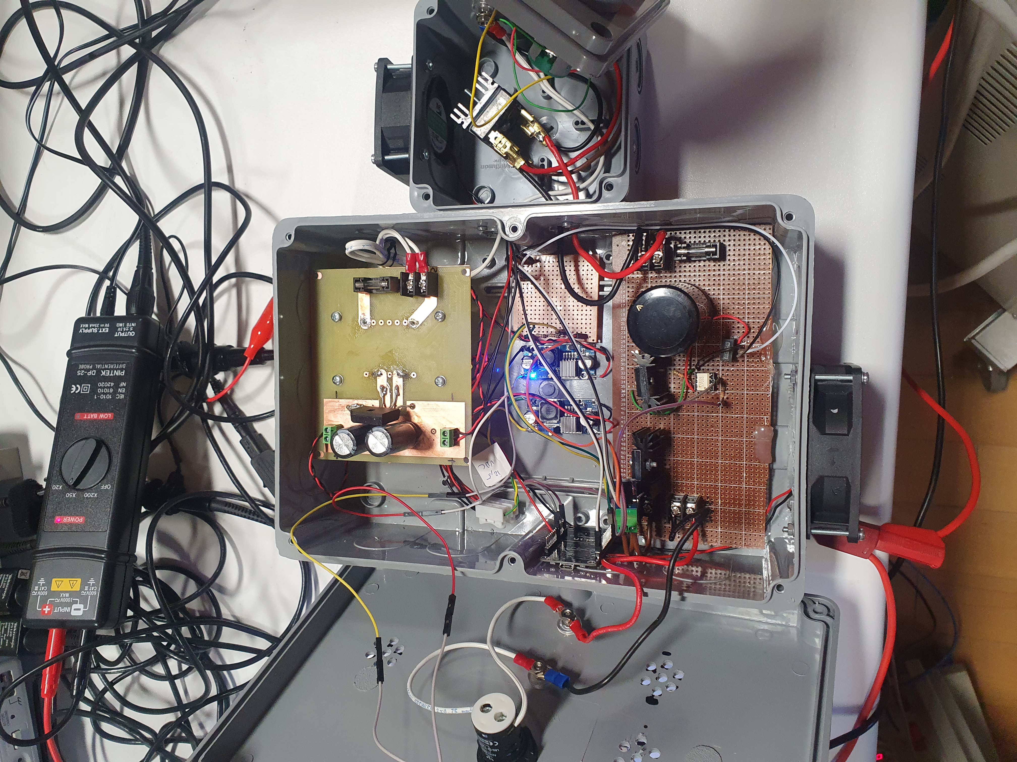
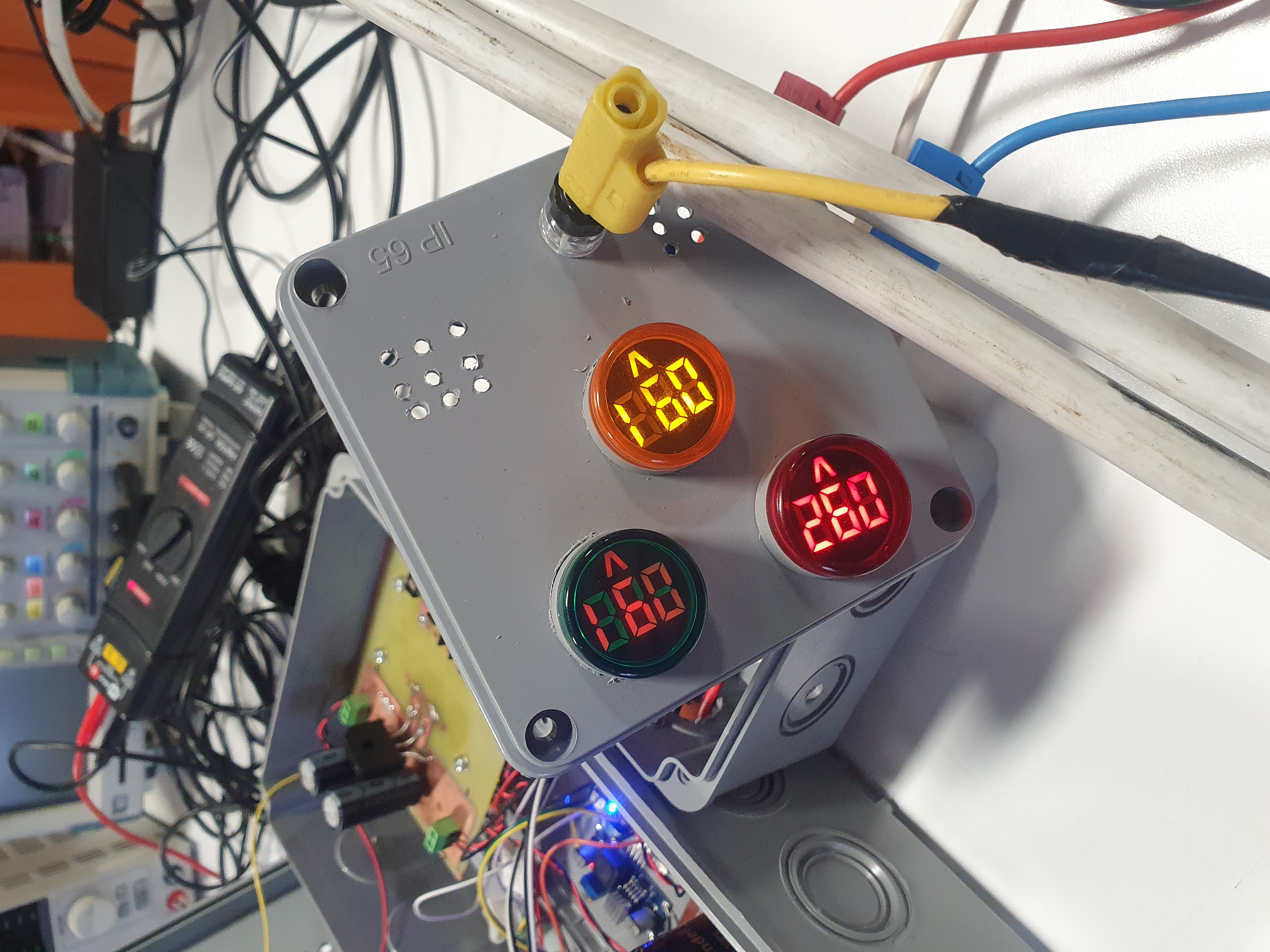
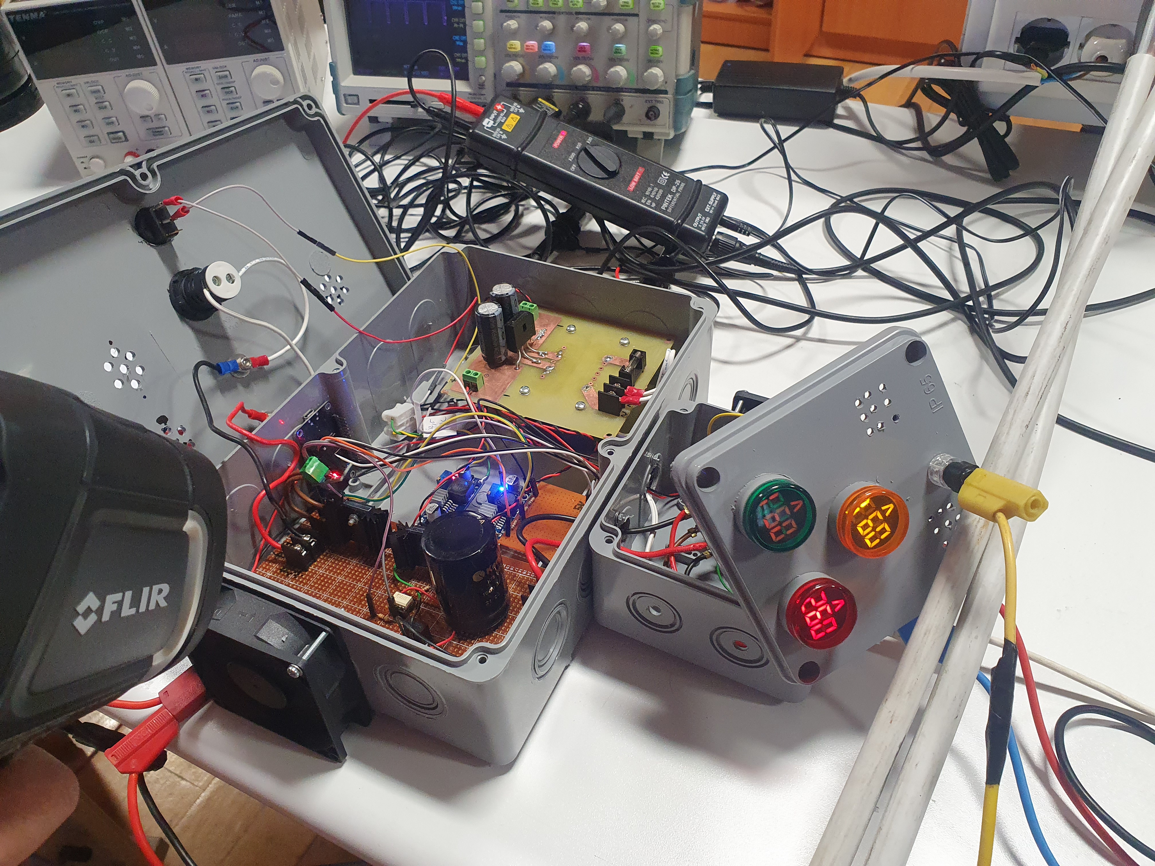
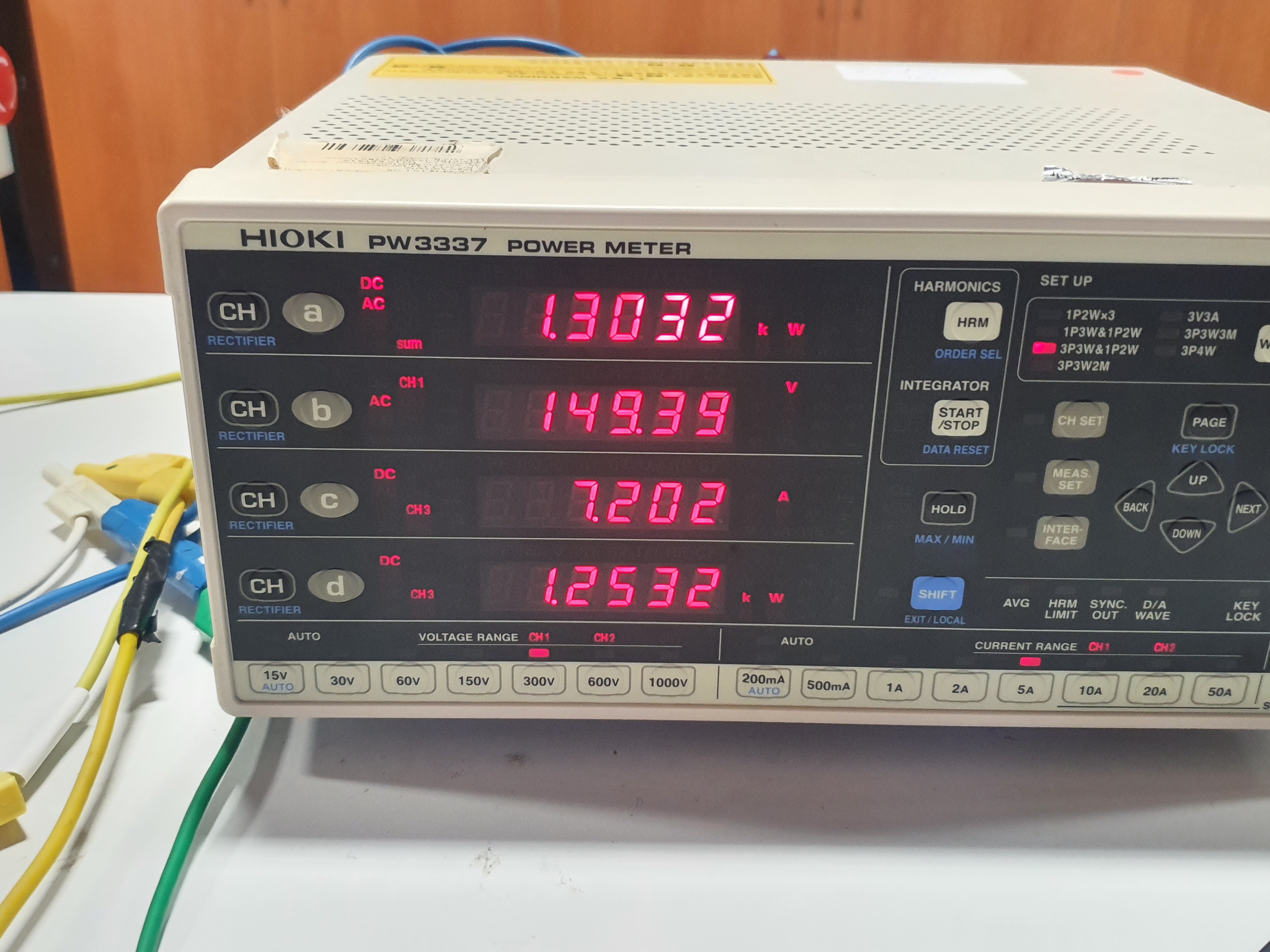
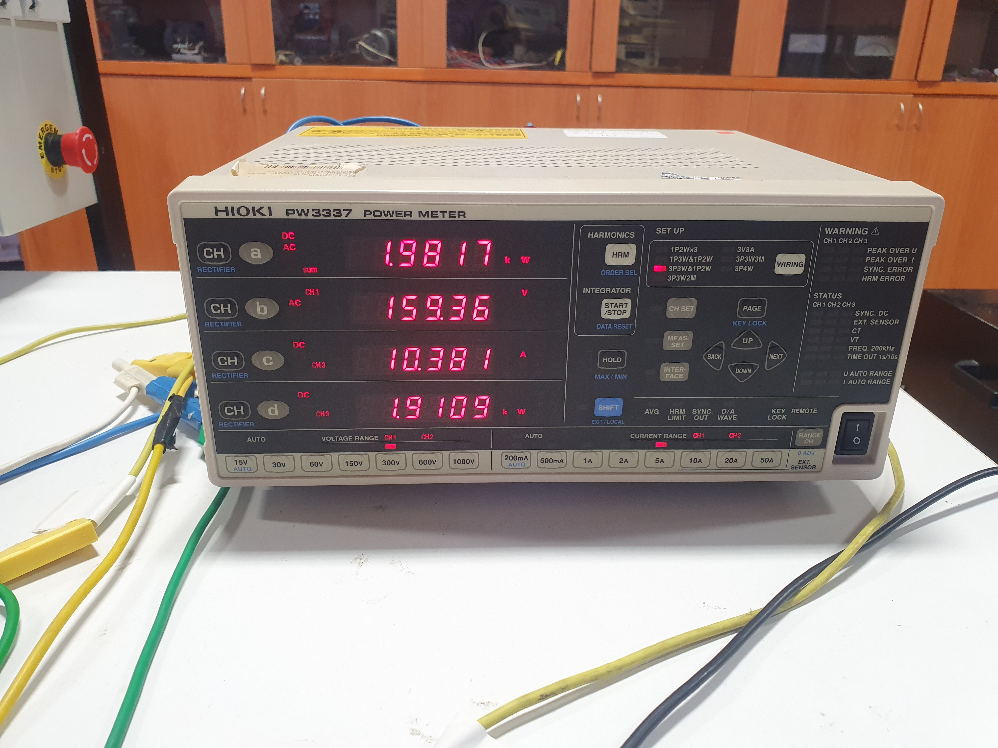
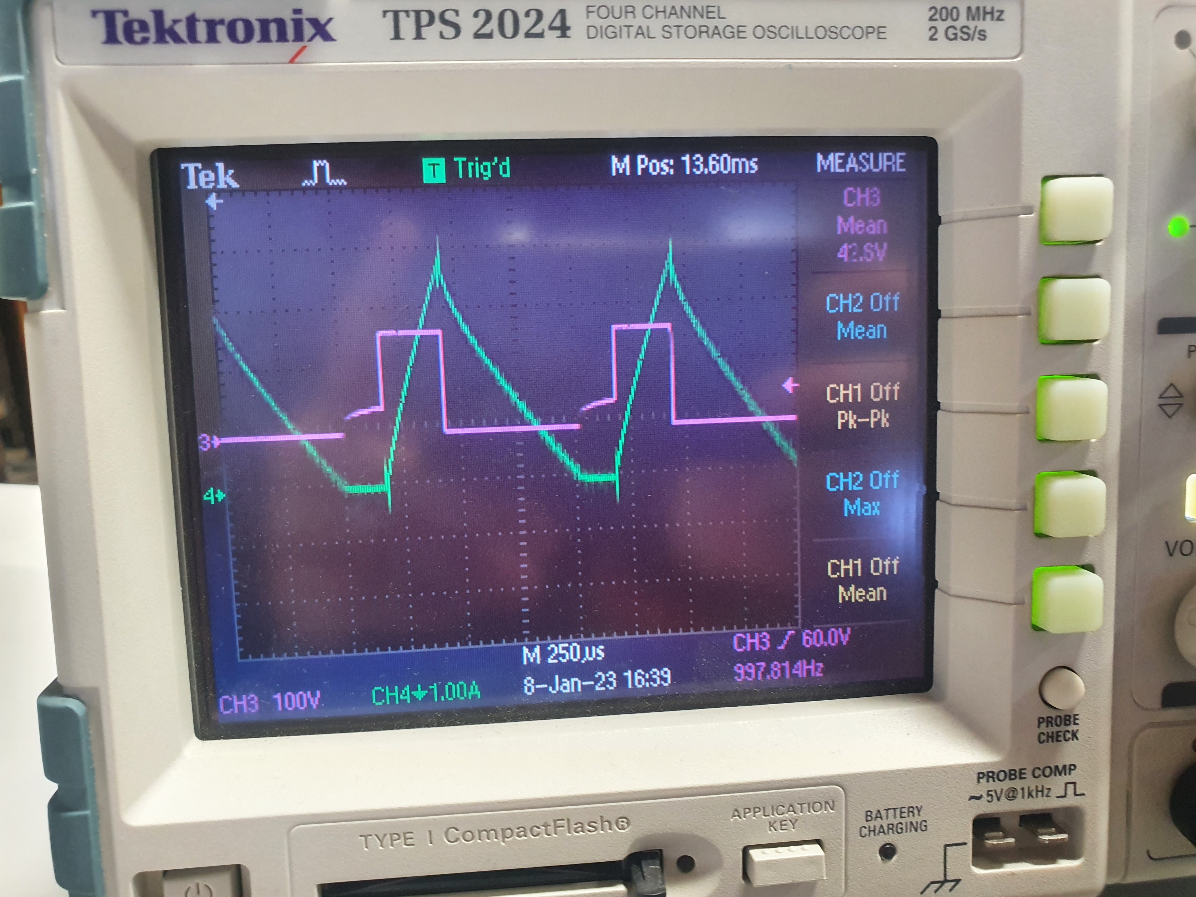
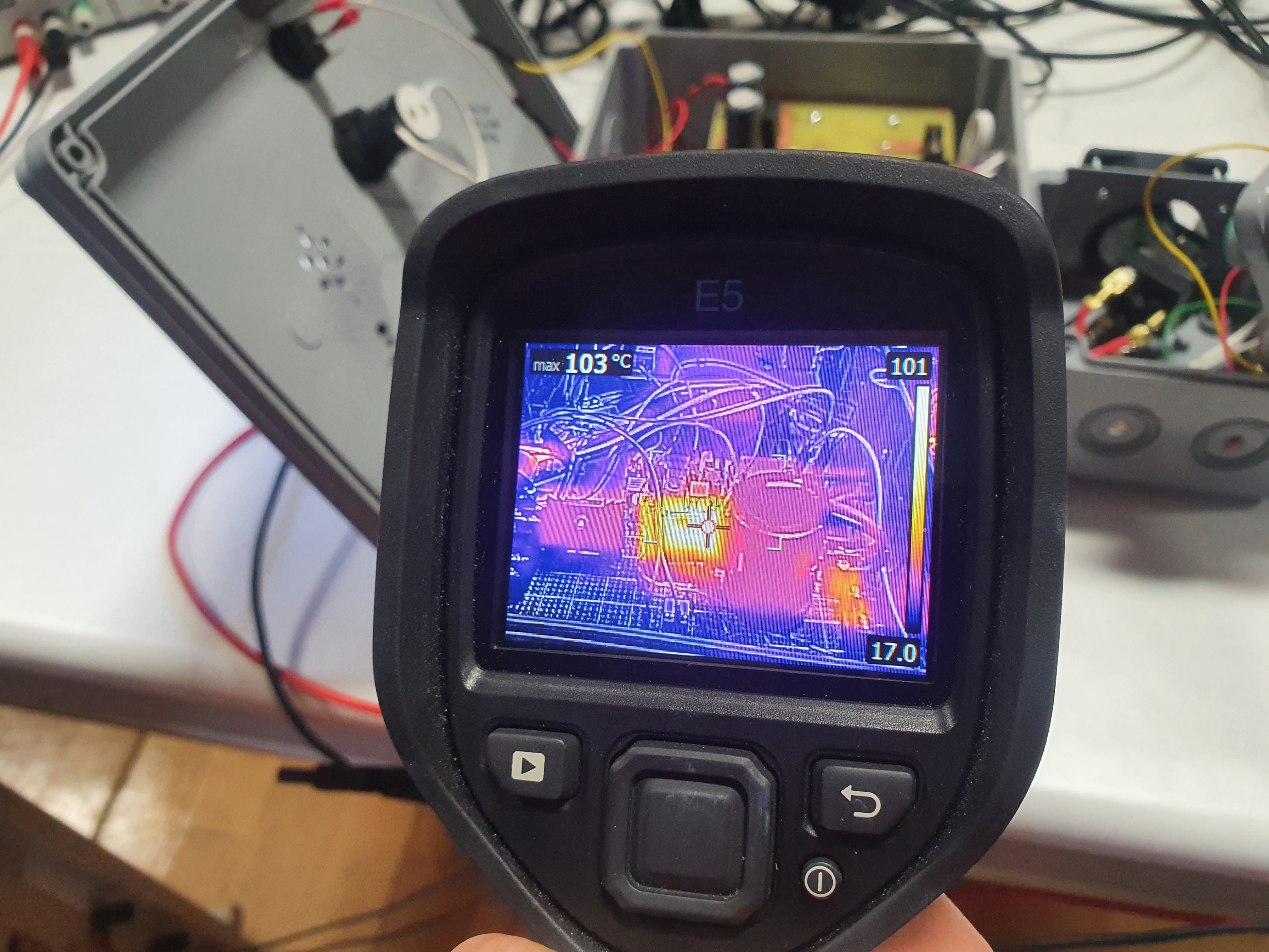
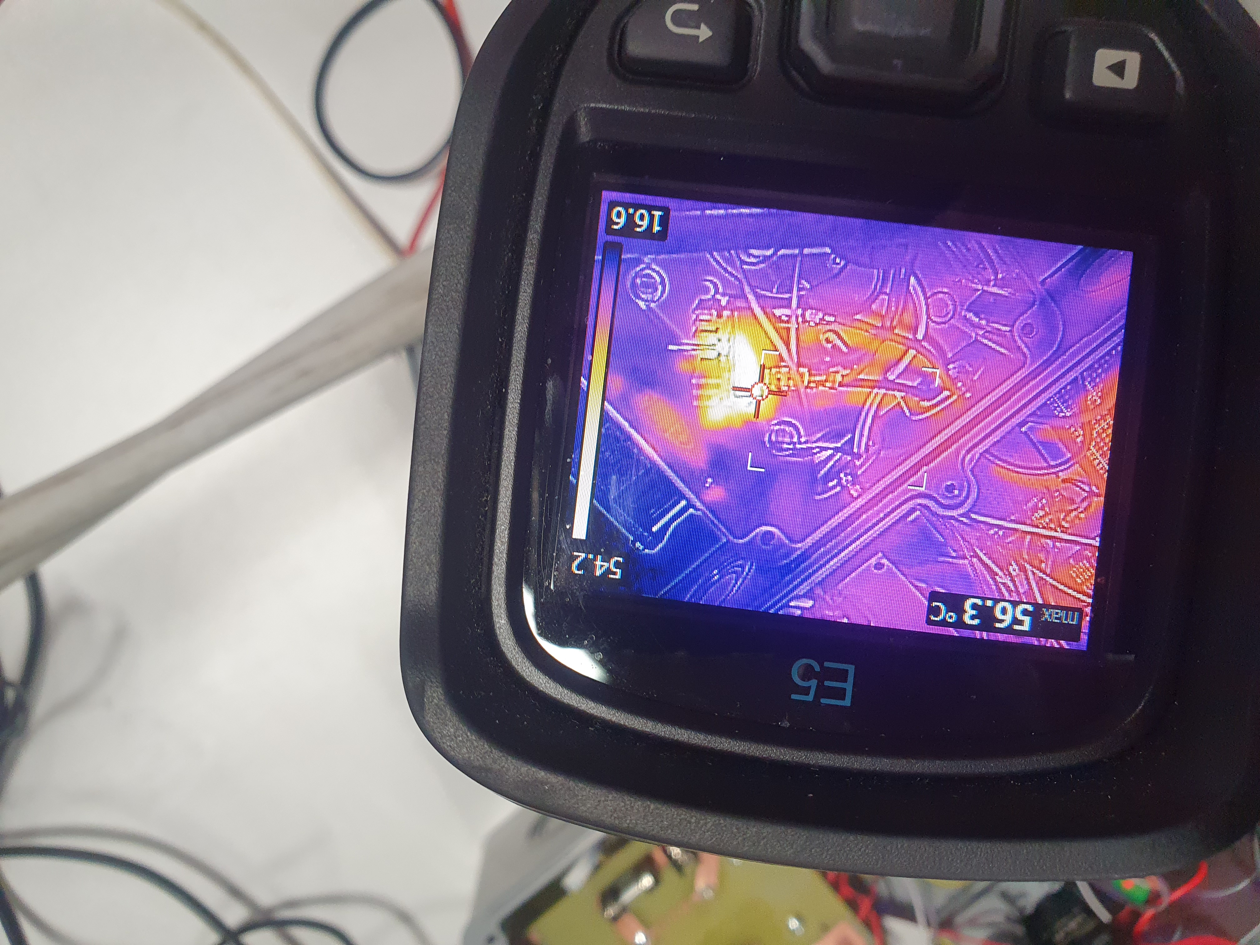
Webdemo could be seen via following the link below:
https://medogan.com/test_server_demo/463_esp_webdemo.html
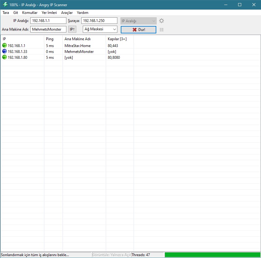
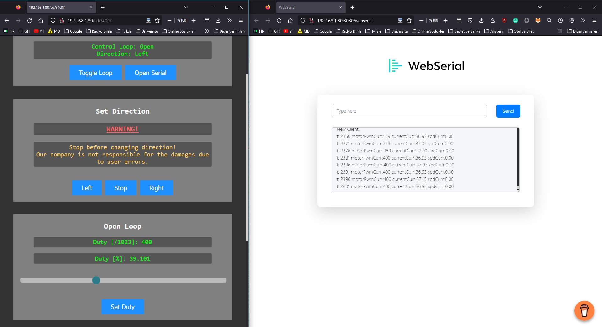
https://www.youtube.com/watch?v=8uU4kF-YDas
https://www.youtube.com/watch?v=bq63kfShjrk
https://www.youtube.com/watch?v=6NDupYknA6s
https://www.youtube.com/watch?v=Q2luOk-gndQ
https://www.youtube.com/watch?v=HJyMbZKjLFo
IRFP460 was not used in the project because it is not supplied by the University and its is expensive and we've left only one. [We had 2 but we burned one of them.] IXGH24N60C4D1 N Channel IGBT was used due to it is supplied by the University .
| Qty | Value | Footprint | References |
|---|---|---|---|
| 8 | R_US | Resistor_THT:R_Axial_DIN0204_L3.6mm_D1.6mm_P7.62mm_Horizontal | R1, R2, R3, R4, R5, R6, R7, R8 |
| 4 | IXGH24N60C4D1 | Package_TO_SOT_THT:TO-247-3_Horizontal_TabUp | Q1, Q2, Q3, Q4 |
| 4 | ROE-0512S | Module:roe0512 | PS1, PS2, PS3, PS4 |
| 4 | TLP250 | Package_DIP:DIP-8_W7.62mm | U1, U2, U3, U4 |
| 2 | Conn_01x03_Male | Connector_PinHeader_2.54mm:PinHeader_1x03_P2.54mm_Vertical | J4, J6 |
| 1 | C_Polarized_US | Capacitor_THT:CP_Radial_D30.0mm_P10.00mm_SnapIn | C1 |
| 1 | HV_IN | TerminalBlock_MetzConnect:TerminalBlock_MetzConnect_Type171_RT13702HBWC_1x02_P7.50mm_Horizontal | J1 |
| 1 | currentSens | TerminalBlock_MetzConnect:TerminalBlock_MetzConnect_Type171_RT13702HBWC_1x02_P7.50mm_Horizontal | J5 |
| 1 | motorOut | TerminalBlock_MetzConnect:TerminalBlock_MetzConnect_Type171_RT13702HBWC_1x02_P7.50mm_Horizontal | J3 |
| 1 | vin5 | TerminalBlock_MetzConnect:TerminalBlock_MetzConnect_Type171_RT13702HBWC_1x02_P7.50mm_Horizontal | J2 |

Elektropac/MCS_Control
All the firmware for Control module

emir-altunkol/EE463-HardwareProject
This is a repository for the term project of the EE463 Static Power Conversion I course given by METU EEE department. It is a DC motor drive project, whose details are included in the course repository.


Millisman/EG8010
Collection of designs for the EG8010 (ASIC for single-phase SPWM control H-bridge)

HNadeemTahir/AI_Inverter_Project
NgSpice Digital Twin of a complete off-grid solar power system: H-Bridge inverter (220V/50Hz, PI control, electro-thermal IGBT modeling) and 4kW MPPT boost converter (UC3843 analog control, KCL summing node, gate drive…


Abineshpk007/KICAD-boost-converter-gate-pulse-from-DSP-
This is my PCB, there are many outer like it but this is mine

Andy18650/GB2-2025-team4
GitHub repository for Cambridge University Engineering part IIA project GB2: Electrical Power, Team 4
It measures 216 × 121 mm and has 2 copper layers, 1.6 mm thick.
27 parts, built around the ROE-0512S and TLP250(F). The full list of its parts is on this page, with links to each part's symbol and footprint where PCBKit's library has them.
From the Mehmet-Emre-Dogan/EE463_2022_TermProject repository on GitHub, at the commit this page was made from: the board is pcbDesigns/deprecated/hBridge/hBridge/hBridge.kicad_pcb and its schematic pcbDesigns/buck/buck/buck.kicad_sch. PCBKit opens the board in the browser, with nothing to install.
Its repository states no licence, so its author keeps all rights: ask Mehmet-Emre-Dogan before reusing the design.
