NgSpice Digital Twin of a complete off-grid solar power system: H-Bridge inverter (220V/50Hz, PI control, electro-thermal IGBT modeling) and 4kW MPPT boost converter (UC3843 analog control, KCL summing node, gate drive characterization).
MPPT Booster 4kW Hardware is an open-source printed circuit board by HNadeemTahir, from the HNadeemTahir/AI_Inverter_Project repository on GitHub. It is a 2-layer board of 304.6 × 105.7 mm with 115 parts on 77 nets, routed with 941 tracks and 22 vias.
It is built around the MC34072D, PCF8574P and TLP250(F), with the BC547 and BC337 among its other parts. Its parts include 58 resistors, 23 capacitors, 10 transistors, 6 diodes and 5 ICs. It belongs with the power boards of this library.
Solar Inverter & MPPT Booster — Simulation to Hardware
NgSpice simulation and KiCad PCB design of a complete off-grid solar power system. The simulation uses manufacturer SPICE models (not ideal switches) and translates dsPIC30F2010 firmware logic into behavioral equations so the control loops can be validated before building hardware.
Two power conversion stages, developed across 10 versions:
H-Bridge Inverter — Single-phase 220V/50Hz pure sine wave output using FGY75T120SWD IGBTs, unipolar SPWM, closed-loop PI voltage regulation, electro-thermal monitoring, and hardware fault protection.
4kW MPPT Boost Converter — DC-DC front-end regulating a variable 120V–350V PV string to a stable 380V DC bus, controlled by a UC3843 analog controller slaved to a dsPIC30F2010 MCU.
Note on Methodology
The workflow here — simulate with real device models, sweep parameters with Python, train a surrogate model, then route the PCB — is not specific to boost converters. The same approach works for any power stage where you need to predict switching losses and thermal behavior before committing to hardware. I have used variations of this on inverter gate drives, motor current loops, and industrial servo tuning.
Project Phases at a Glance
Version
Focus Area
Key Achievement
V1.0
Environment Setup
NgSpice + library structure established
V2.0
Half-Bridge SPWM
Ideal switching, basic sine generation
V3.0
Physical IGBT Models
Real FGY75T120SWD switching behavior
V4.0
Full H-Bridge + LC
Unipolar SPWM, motor load, phase lag verified
V5.0
Closed-Loop PI Control
ZMPT101B sensor delay, voltage regulation
V6.1
Dead-Time + Thermal
2µs shoot-through protection, Foster RC model
V6.3
Python Automation
Batch simulation, CSV data extraction
V6.5
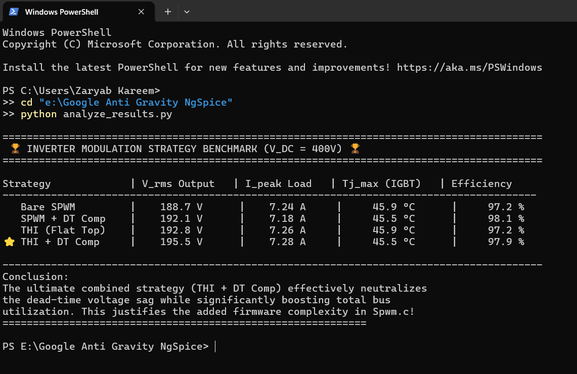
Modulation Benchmark
THI + Dead-Time compensation matrix
V7.0
Surrogate Model
Scikit-Learn Random Forest predictor
V8.0
4kW MPPT Converter
Feed-forward + PI boost, 3 test profiles
V9.0
UC3843 Control Loop
Analog-digital MPPT integration, gate physics
V10.0
Hardware PCB
KiCad layout, DRC-clean, 3D-verified
Hardware Implementation (KiCad)
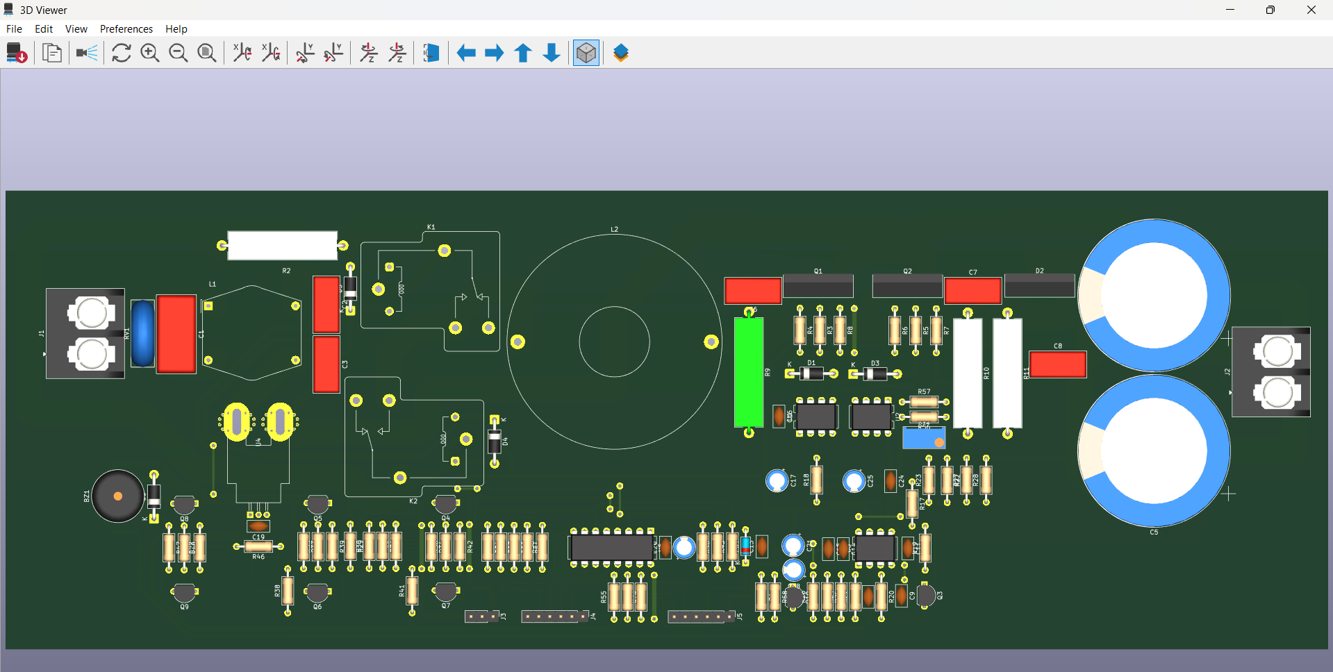
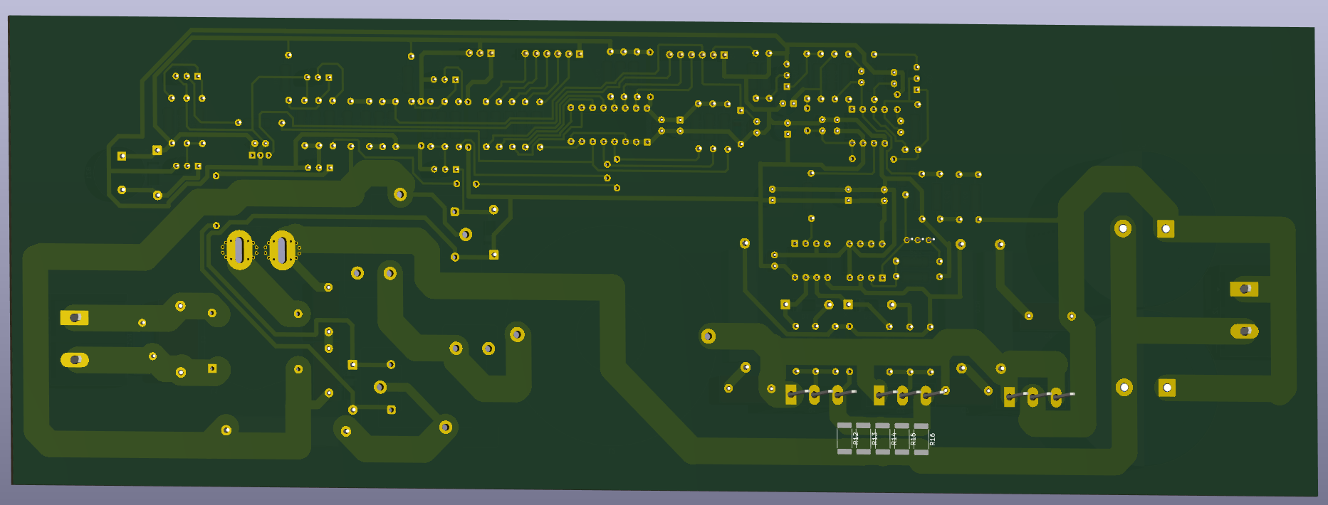
The 4kW MPPT booster control board, designed in KiCad 9.0. DRC-clean. The schematic and layout match the UC3843 + dsPIC control architecture from V8.0 and V9.0 simulations.
High-current paths (inductor → IGBT → diode → output caps) use wide copper pours with thermal relief pads to handle 20A+ continuous current
Gate driver isolation — FOD3150 optoisolators provide galvanic separation between the dsPIC logic ground and the power stage ground
Current sensing — INA181A2 shunt amplifier placed directly adjacent to the sense resistor to minimize noise pickup
Analog control section — UC3843, slope compensation network, and RC timing components grouped together with short trace runs
Version 9.0 — UC3843 Analog Control Loop Integration
This version implements the hardware-level control architecture of the 4kW MPPT booster. It moves beyond behavioral SPICE switches into a real analog control loop where a UC3843 peak-current-mode PWM controller is directly slaved to the dsPIC30F2010 MCU via a KCL-balanced voltage summing node.
Engineering Targets Achieved
Target
Method
Status
Analog-digital MPPT interface
KCL summing node on UC3843 Pin 2
✅ Proven
Cold-boot explosion prevention
10kΩ pull-up on dsPIC OC1 PWM line
✅ Proven
Precharge relay MCU isolation
2N2222 NPN driving 40A contactor coil
✅ Proven
Sub-harmonic oscillation fix
2N3904 NPN emitter-follower slope compensation
✅ Proven
100ns turn-on noise rejection
1kΩ + 470pF LEB filter on UC3843 Pin 3
✅ Proven
IGBT Miller plateau characterization
Asymmetric gate drive: 15Ω ON / 5.6Ω+D OFF
✅ Proven
dsPIC PWM-to-analog conversion
10kΩ + 4.7µF RC filter: 3.3Hz cutoff
✅ Proven
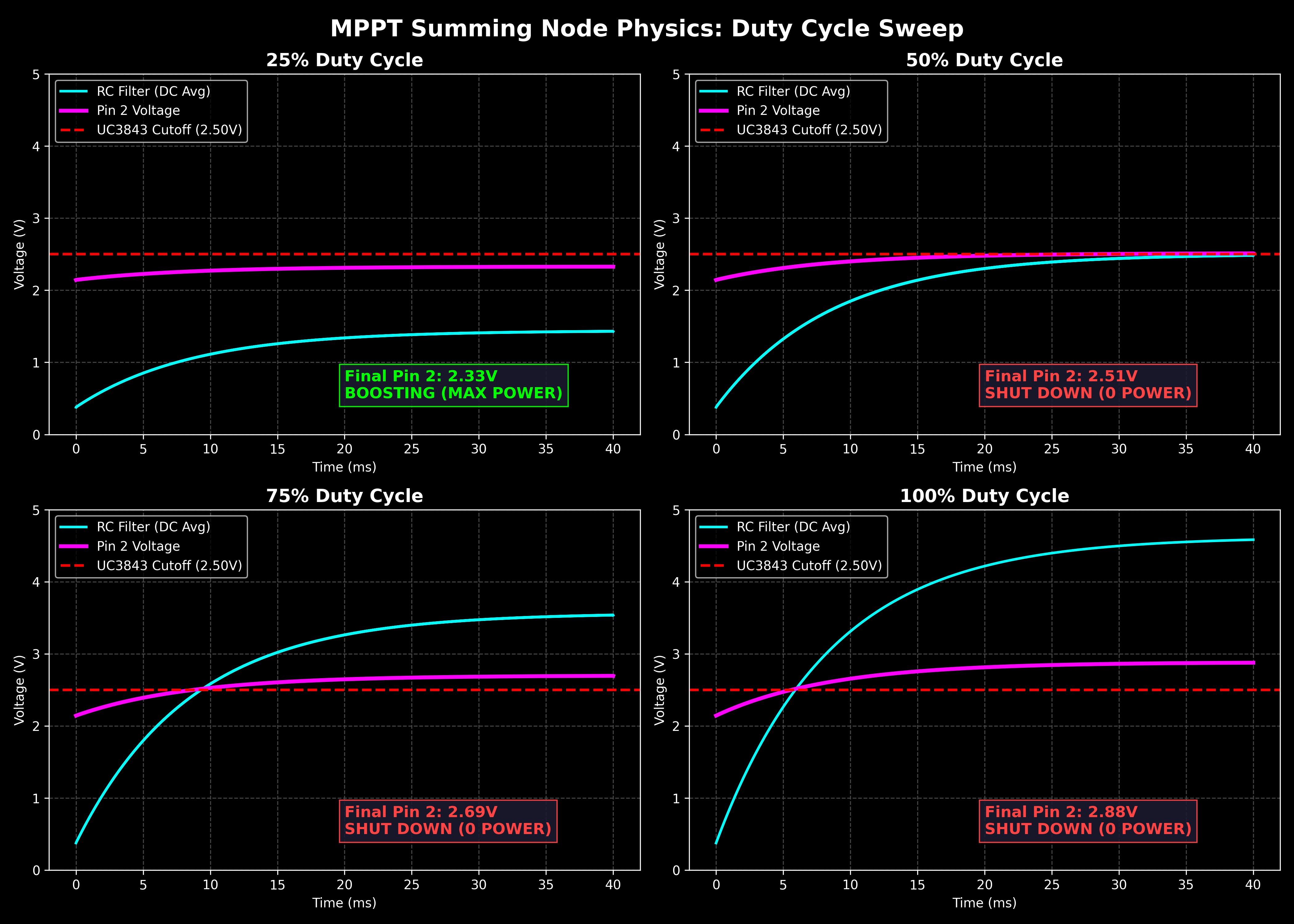
Test 1 — MPPT Summing Node: dsPIC Duty Cycle Sweep
Four-point parametric sweep of the dsPIC OC1 PWM duty cycle. Proves the KCL summing node physics: at 25% duty cycle, Pin 2 settles below 2.50V and the UC3843 boosts at maximum power. At 50%–100%, Pin 2 rises above the 2.50V threshold and the converter shuts down in a controlled manner. The 10kΩ pull-up resistor ensures this safe state is the default during MCU boot.
dsPIC PWM
RC Filter Output
Pin 2 Voltage
UC3843 State
25%
1.25V
2.33V
Boosting (MAX POWER)
50%
2.50V
2.51V
Shut Down
75%
3.75V
2.69V
Shut Down
100%
5.00V
2.88V
Shut Down
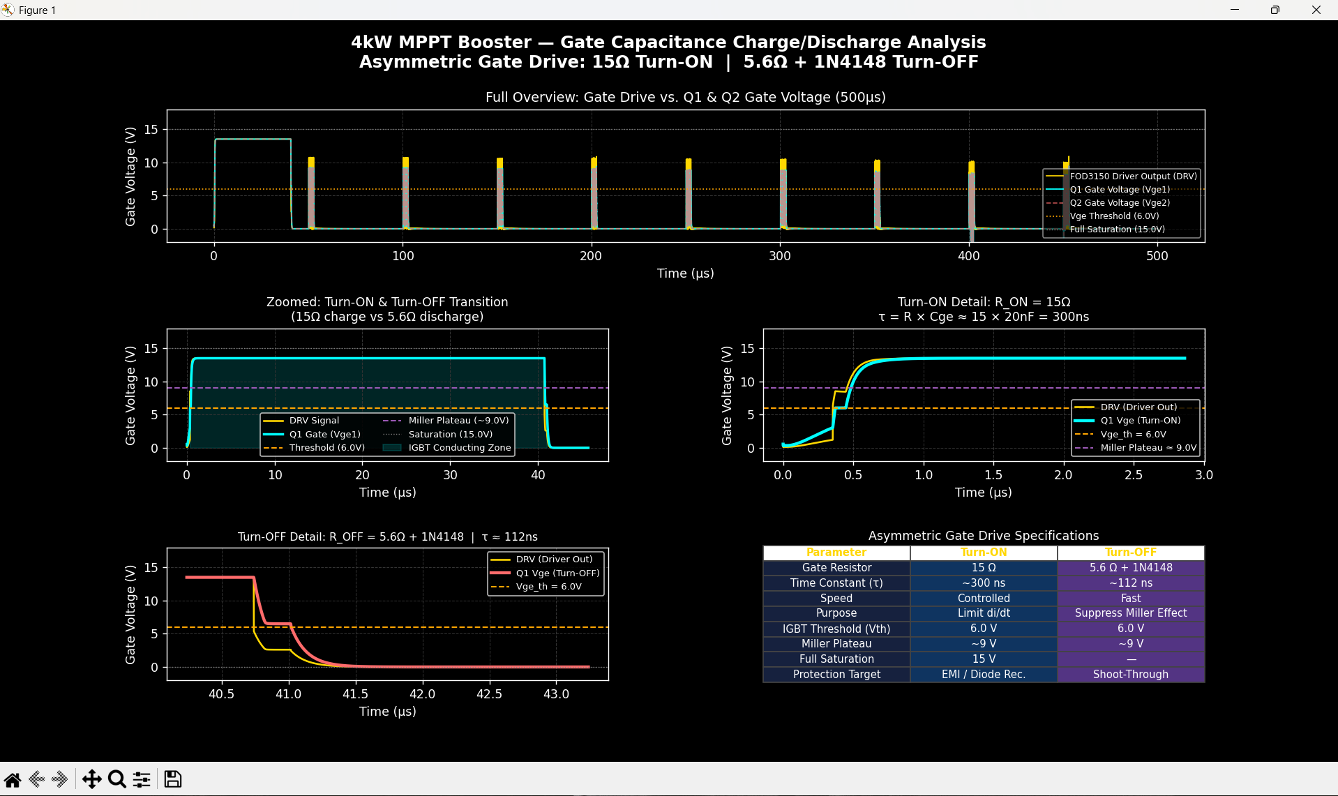
Test 2 — Gate Capacitance Charge/Discharge Analysis
500µs high-resolution transient analysis of the asymmetric gate drive network on the STGW60H65DFB parallel IGBT pair. Characterizes the Miller Plateau crossing, threshold voltage events, and the turn-on/turn-off time constants resulting from the 15Ω / 5.6Ω+1N4148 resistor-diode network.
Parameter
Turn-ON
Turn-OFF
Gate Resistor
15 Ω
5.6 Ω + 1N4148
Time Constant (τ)
~300 ns
~112 ns
Purpose
di/dt limiting, diode recovery ctrl
Miller effect suppression, shoot-through prevention
IGBT Threshold (Vth)
6.0 V
6.0 V
Miller Plateau
~9 V
~9 V
Full Saturation
15 V
—
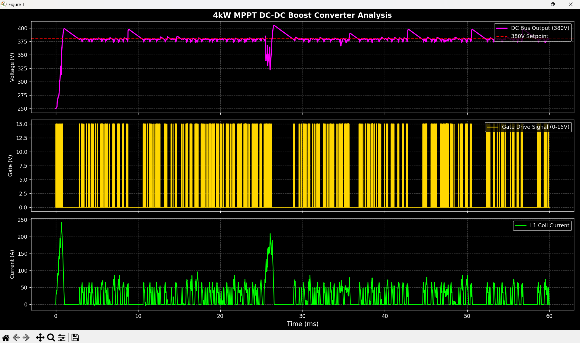
Test 3 — UC3843 Closed-Loop Boost Converter
Full closed-loop simulation of the UC3843 controlling the power stage. Shows the DC bus regulation, inductor current waveform, and the 20kHz gate drive signal across the full 60ms transient window.
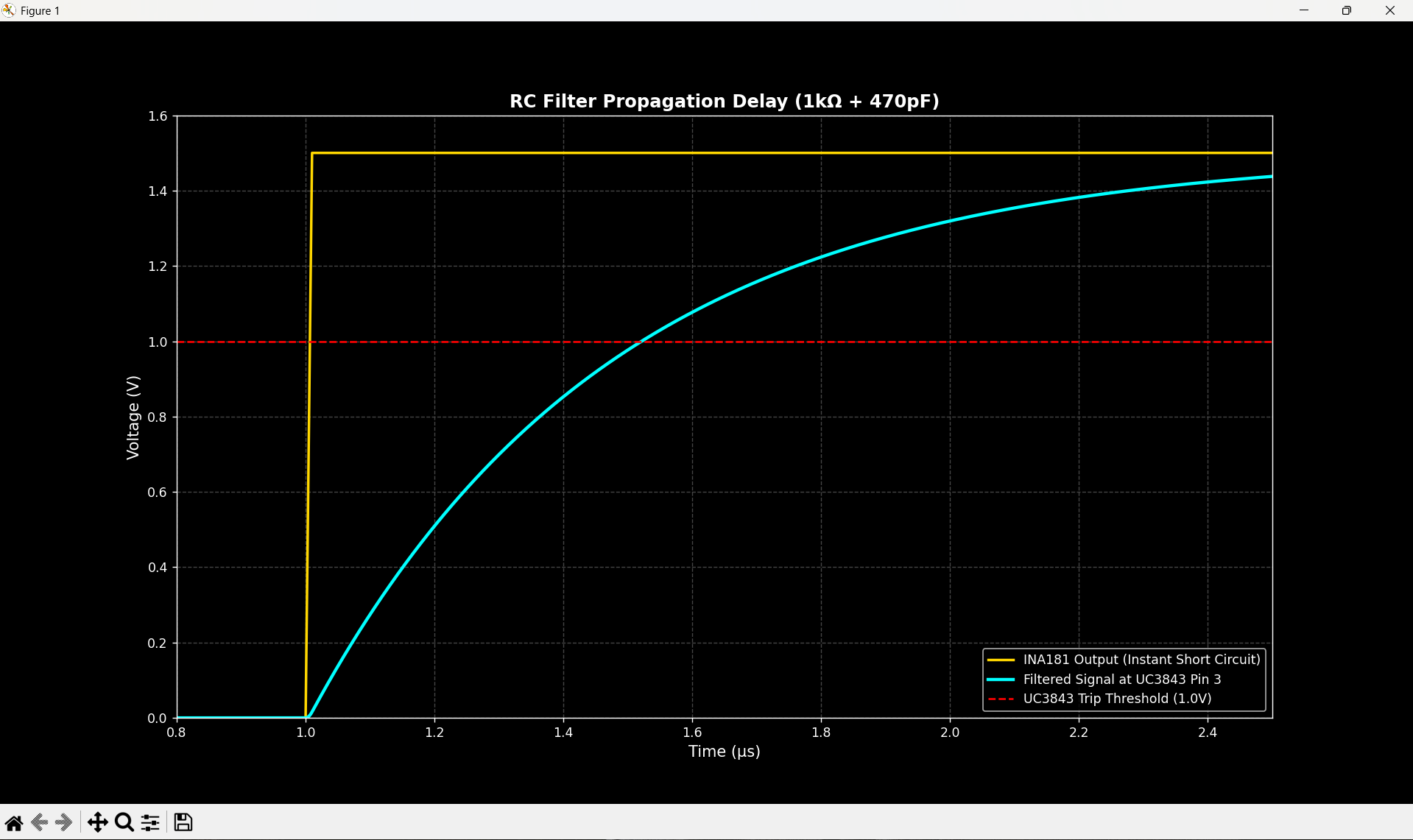
Test 4 — LEB Filter: 470ns Current Sense Propagation Delay
Step-response analysis of the Leading Edge Blanking (LEB) filter at UC3843 Pin 3. A simulated dead-short event causes the INA181 output to jump instantaneously to 1.5V. The 1kΩ + 470pF RC filter delays the signal reaching the 1.0V trip threshold by 470ns — exactly the blanking window required to mask IGBT turn-on current spikes while remaining fast enough to detect a genuine short circuit within one switching cycle.
Version 8.0 — 4kW MPPT Boost Converter
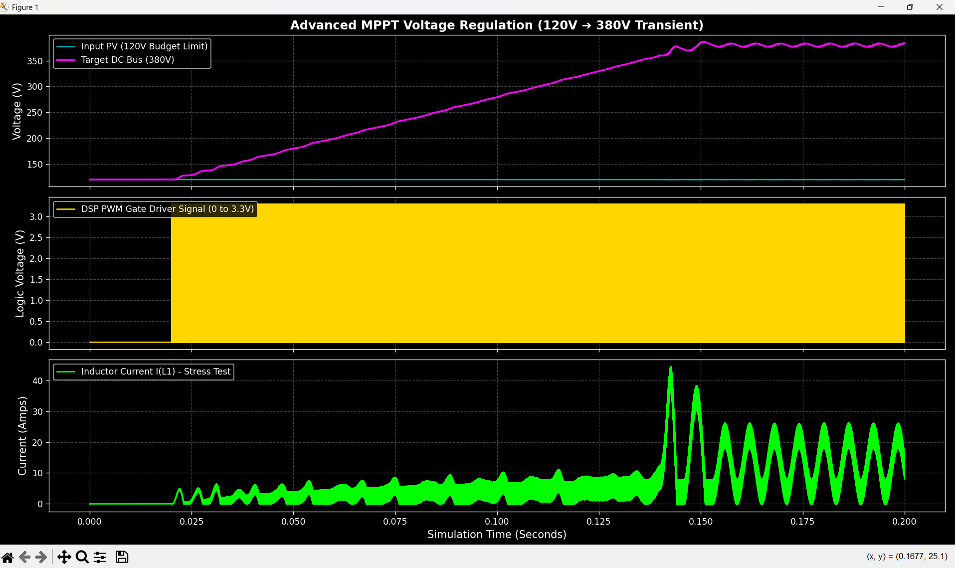
Full power-stage simulation of the 4kW DC-DC booster. Feed-forward + PI control architecture handles 3-panel to 8-panel PV string inputs.
Booster Specifications
Parameter
Value
Input Range
120V – 350V DC
Output
380V DC (regulated)
Max Power
4000W
Switching Frequency
20kHz
IGBTs
2× STGW60H65DFB (650V/60A, parallel)
Boost Diode
STTH3006D (600V/30A, 35ns Trr)
Gate Driver
FOD3150 (optically isolated)
Control
Feed-Forward + PI with anti-windup
Validated Test Profiles
Profile
Input
Load
Steady State
Verdict
3-Panel String
120V
1500W
380V flat
PASS
5-Panel String
250V
3000W
380V flat
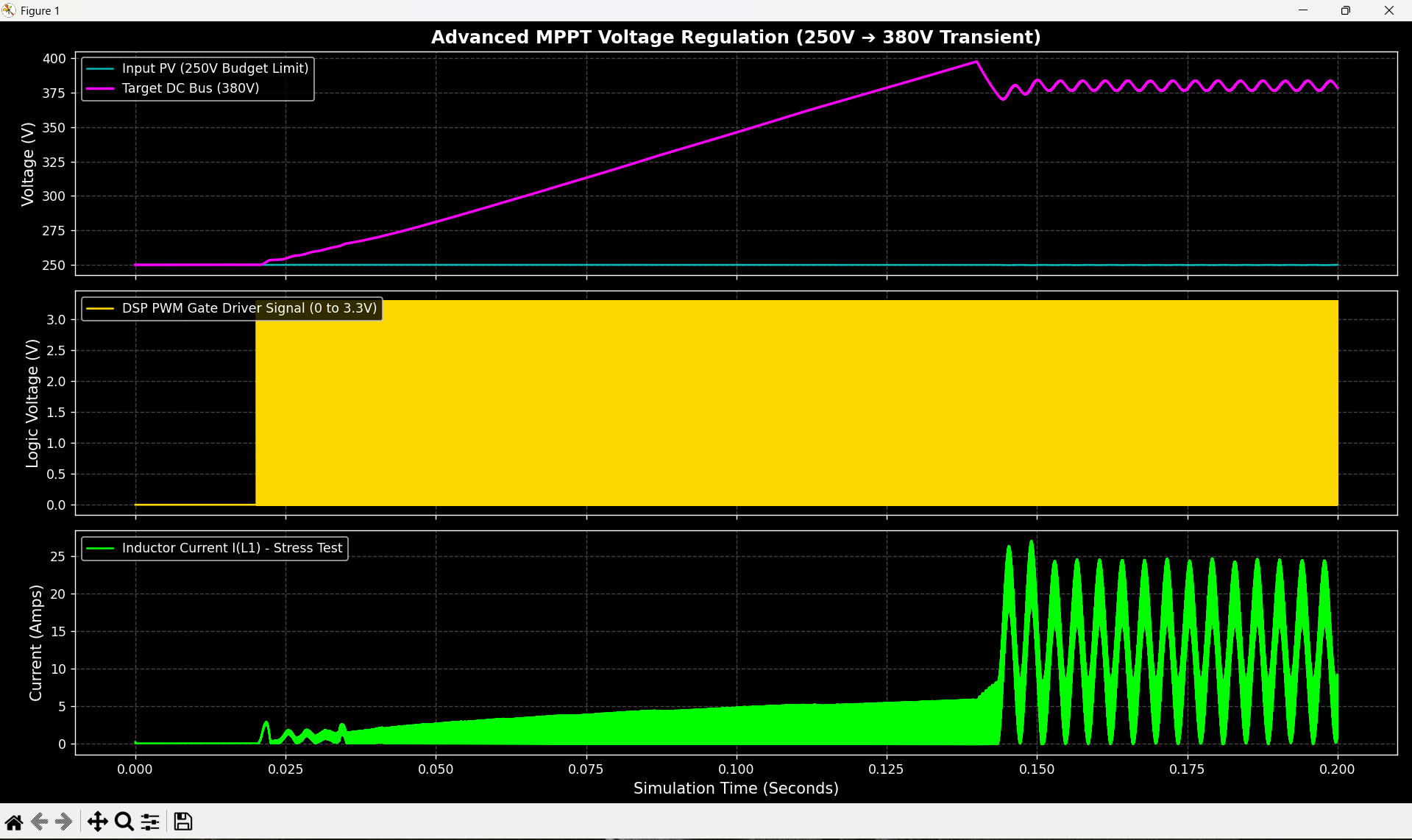
PASS
8-Panel String
350V
4000W
380V ±10V†
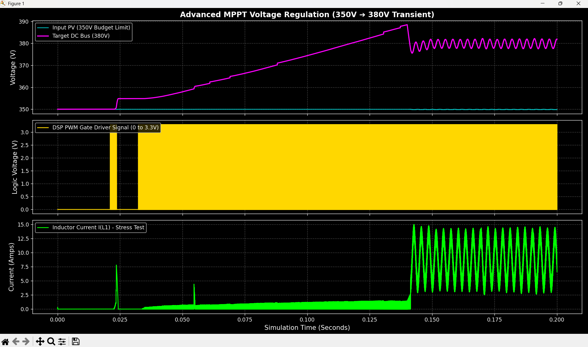
PASS
† Bounded oscillation at 350V is LC resonance at near-unity boost ratio. Eliminated in firmware by a single-coefficient EMA filter: vbus_filt = 0.015 * raw + 0.985 * filt.
Profile 1: 120V → 380V (1500W, Boost Ratio 3.17×)
Profile 2: 250V → 380V (3000W, Boost Ratio 1.52×)
Profile 3: 350V → 380V (4000W, Boost Ratio 1.09×)
Critical Design Findings
Feed-forward is mandatory at high boost ratios. Without it, the PI controller cannot reach 68% duty cycle fast enough, producing 250A+ inductor current spikes on startup.
Load connection sequence matters — connecting the inverter load before the DC bus reaches 90% of target produces 400A+ surge currents due to the discharged output capacitor acting as a short circuit.
Firmware EMA filter required at 350V operating point to damp the LC resonance visible in the 350V simulation profile.
Version 7.0 — Surrogate Model (Scikit-Learn)
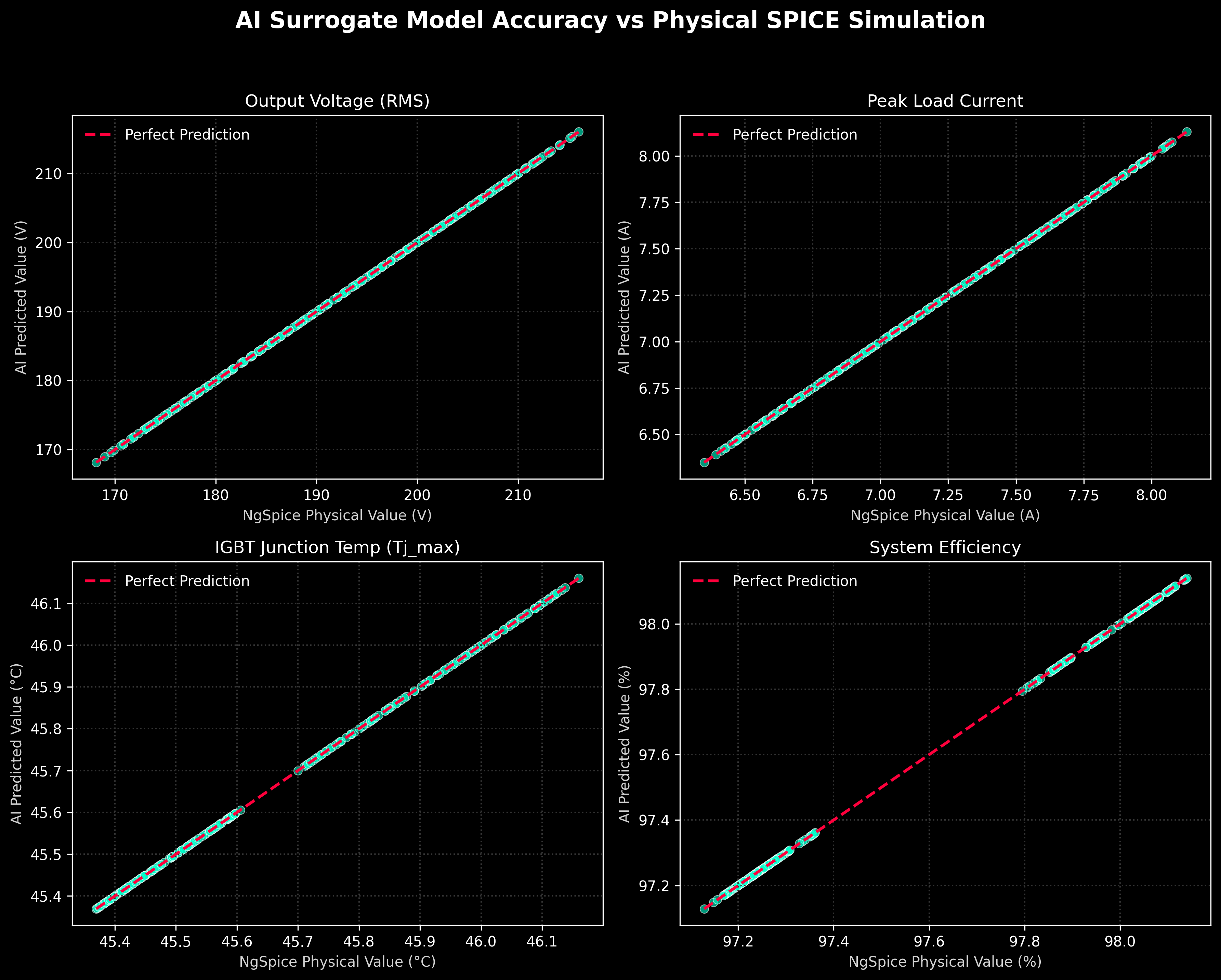
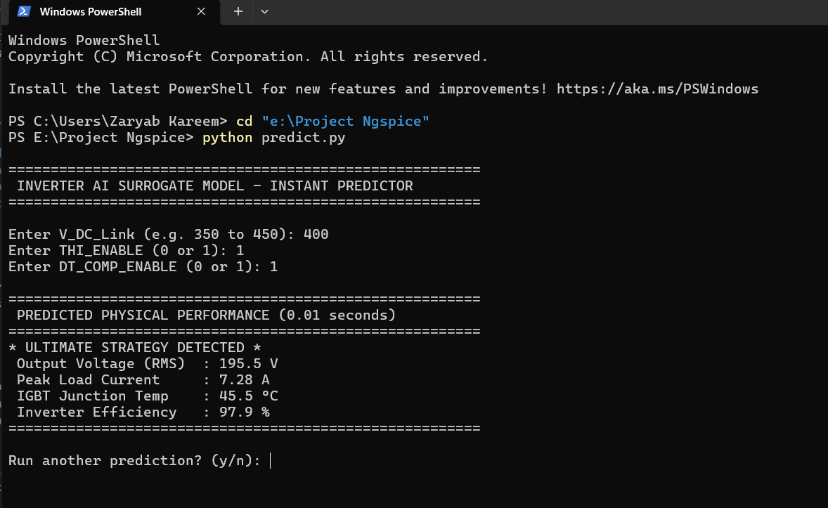
A Random Forest Regression model trained on 204 NgSpice simulations generated by the parametric data factory. The predictor approximates IGBT junction temperature, efficiency, and AC output voltage for any input condition in under 0.01 seconds — eliminating the need to run a full transient simulation during firmware tuning.
Surrogate Model Accuracy
Instant Performance Predictor
Version 6.5 — Modulation Strategy Benchmark
Four independently toggled modulation strategies benchmarked against each other using a parametric sweep across 400V DC link conditions.
Strategy Matrix
THI
DT Comp
Strategy
V_rms
Tj_max
Efficiency
OFF
OFF
Bare SPWM
188.7V
45.9°C
97.2%
OFF
ON
SPWM + DT Comp
192.1V
45.5°C
98.1%
ON
OFF
THI Flat-Top
192.8V
45.9°C
97.2%
ON
ON
THI + DT Comp
195.5V
45.5°C
97.9%
The combined strategy recovers 6.8V of AC output. Uncompensated dead-time introduces harmonic distortion that recirculates as I²R heat — compensating it in firmware improves both output voltage and thermal efficiency simultaneously.
Inverter Simulation Results (V6.5 Reference)
Output Voltage — Inductive Motor Load
50Hz output into 20Ω/100mH R-L load. Peak ±311V.
Voltage-Current Phase Lag
Current lags voltage by ~57°. Confirmed: arctan(2π × 50 × 0.1 / 20) = 57.5°.
PI Controller: Reference vs Feedback
ZMPT101B-delayed feedback vs reference. PI controller achieves tracking within 2 cycles.
PI Controller Internal Signals
Error and integral signals. Integral term stabilizes by 20ms.
ZMPT101B Sensor Delay
200µs RC group delay (2kΩ / 100nF) modeled from physical transformer + PCB filter.
Dead-Time Protection — Gate Signals
~2µs dead-time gap between Leg A HS and LS transitions, matching dsPIC DTCON1 register.
DC Bus Energy Flow
Negative current = energy delivery to load. Positive spikes at zero-crossings = inductive freewheeling through body diodes.
Short-Circuit Protection (50A Trip)
0.1Ω dead-short at t=25ms. CT + comparator trips INT0 latch at 50A primary. Current decays through freewheeling path within 1ms.
Electro-Thermal IGBT Junction
Foster RC network output. 50Hz thermal ripple at junction node. Heatsink stable at 45°C.
Dead-Time Validation (Single Event)
Single switching event: both gate signals at 0V for the full 2µs dead-time interval.
Unipolar SPWM Logic
Full 20ms cycle. Leg A switches at 16kHz on the positive half; Leg B clamped. Roles exchange at zero-crossing.
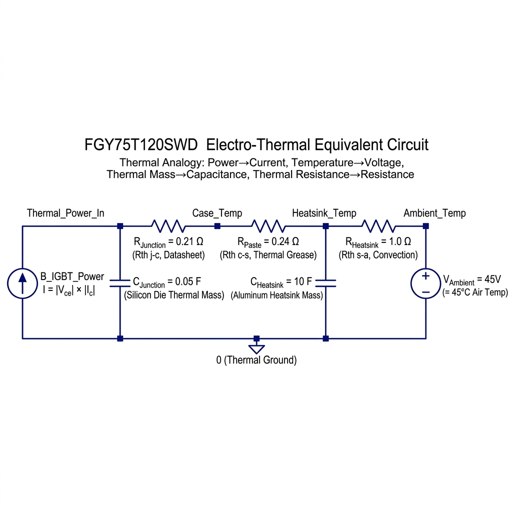
Electro-Thermal IGBT Model
Foster RC network mapping power dissipation to junction temperature. Standard power electronics electro-thermal equivalence:
Thermal Domain
Electrical Equivalent
Power (W)
Current Source (A)
Temperature (°C)
Voltage (V)
Thermal Mass (J/°C)
Capacitance (F)
Thermal Resistance (°C/W)
Resistance (Ω)
Parameters (onsemi FGY75T120SWD datasheet):
Stage
Parameter
Value
Junction to Case
Rth(j-c)
0.21 °C/W
Junction Thermal Mass
Cth
0.05 F
Case to Heatsink
Rth(c-h)
0.24 °C/W
Heatsink to Ambient
Rth(h-a)
1.0 °C/W
Ambient
V_Ambient
45°C (worst-case)
Steady-state at 40W average dissipation per IGBT:
T_junction = 40 × (0.21 + 0.24 + 1.0) + 45 = 103°C — within the 175°C absolute maximum.
python data_factory.py          # Generate 204-simulation training dataset
python train_ai.py              # Train and save Random Forest model
python predict.py               # Instant performance predictor CLI
NgSpice Compatibility Notes
limit() function is not supported in NgSpice 46 B-source expressions.
sdt() integrator is not available — use G-source + Capacitor model.
Current sense amplifier design and PCB layout guidelines
Author
Nadeem Tahir
I have been designing and commissioning inverters, motor drives, and PLC-based industrial machines for 13 years. This project started as a way to validate my booster design before ordering PCBs, and grew into a simulation platform I now use across projects. I am working toward an MS/PhD in robotics and intelligent control.
PCB boards for energy optimalization device. Contactors control for power switching with full optical isolation. Multiple current measurments made with current transformers.
Collection of designs for the EG8010 (ASIC for single-phase SPWM control H-bridge)
201 parts17MIT
Questions
How big is the MPPT Booster 4kW Hardware PCB?
It measures 304.6 × 105.7 mm and has 2 copper layers, 1.6 mm thick.
What parts does the MPPT Booster 4kW Hardware use?
115 parts, built around the MC34072D, PCF8574P, TLP250(F) and BC547. The full list of its parts is on this page, with links to each part's symbol and footprint where PCBKit's library has them.
Where can I download the MPPT Booster 4kW Hardware KiCad files?
From the HNadeemTahir/AI_Inverter_Project repository on GitHub, at the commit this page was made from: the board is hardware/kicad/MPPT_Booster_4kW_Hardware.kicad_pcb and its schematic hardware/kicad/MPPT_Booster_4kW_Hardware.kicad_sch. PCBKit opens the board in the browser, with nothing to install.
Can I use the MPPT Booster 4kW Hardware design in my own project?
Its repository states no licence, so its author keeps all rights: ask HNadeemTahir before reusing the design.


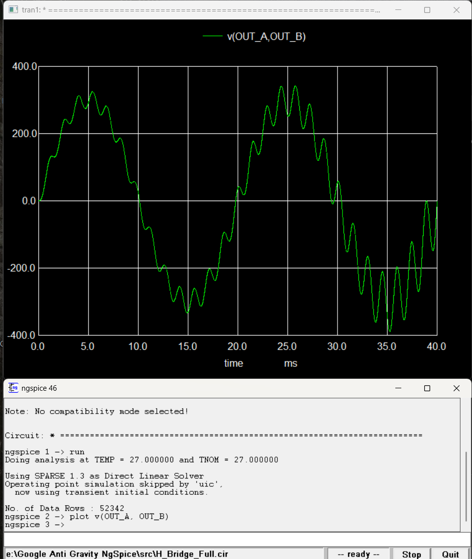 50Hz output into 20Ω/100mH R-L load. Peak ±311V.
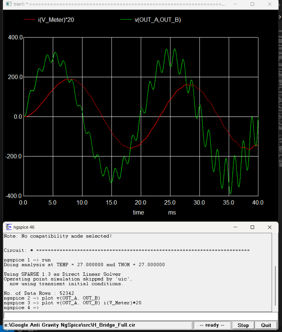 Current lags voltage by ~57°. Confirmed: arctan(2π × 50 × 0.1 / 20) = 57.5°.
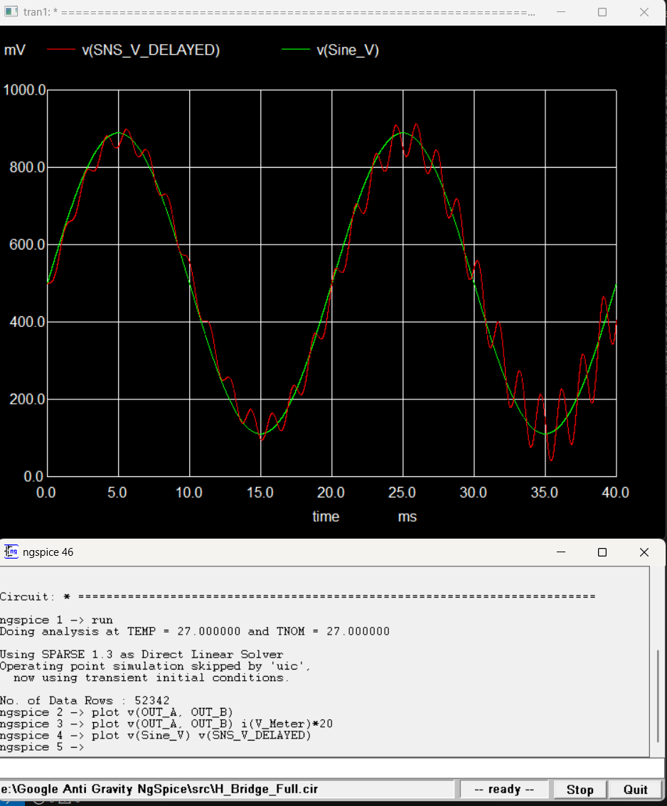 ZMPT101B-delayed feedback vs reference. PI controller achieves tracking within 2 cycles.
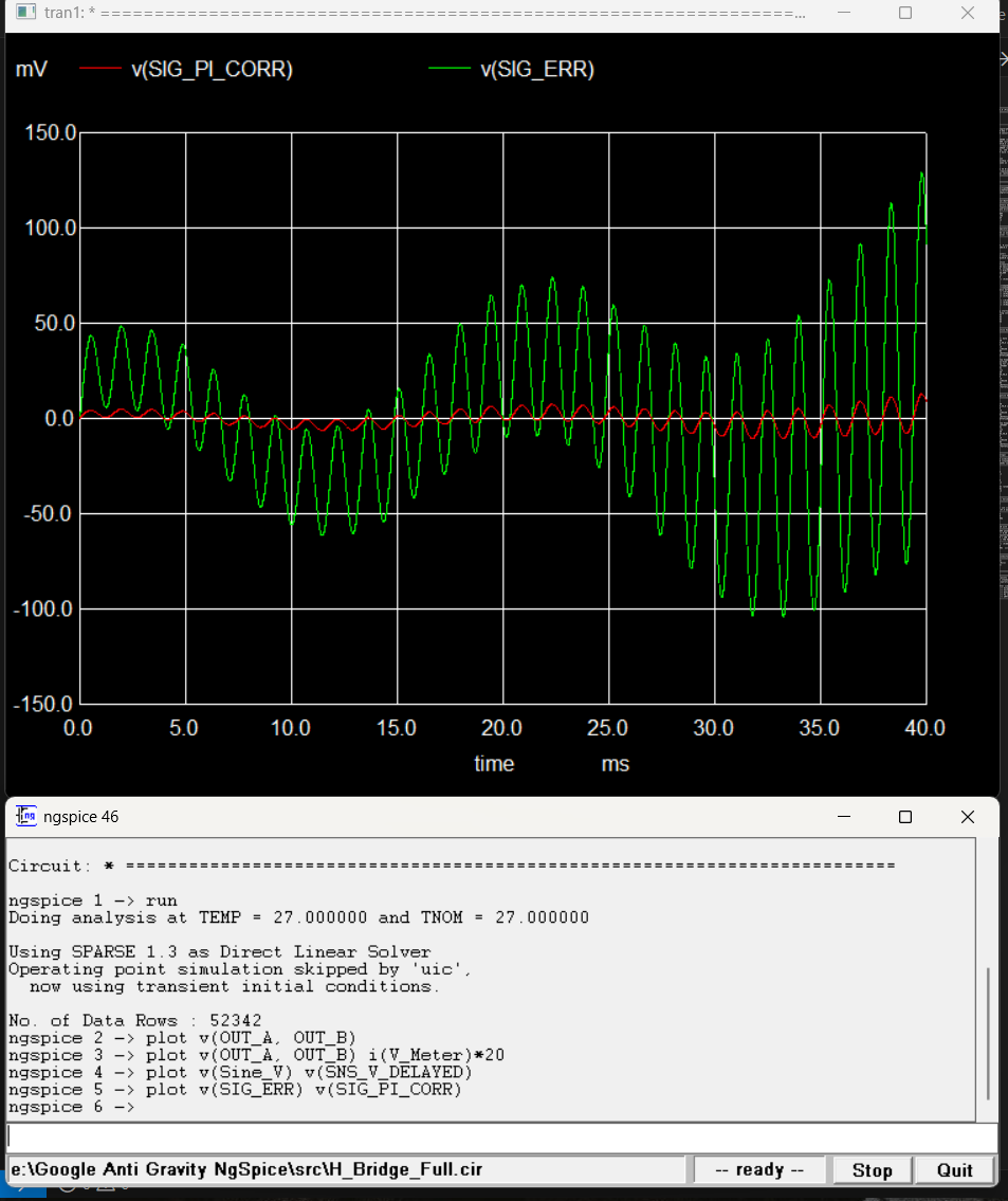 Error and integral signals. Integral term stabilizes by 20ms.
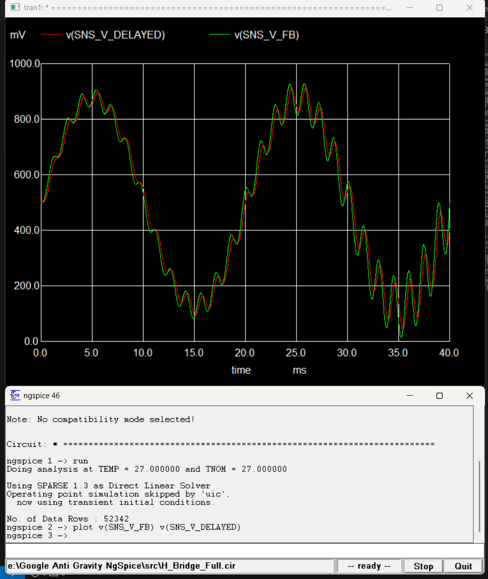 200µs RC group delay (2kΩ / 100nF) modeled from physical transformer + PCB filter.
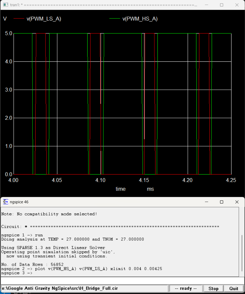 ~2µs dead-time gap between Leg A HS and LS transitions, matching dsPIC DTCON1 register.
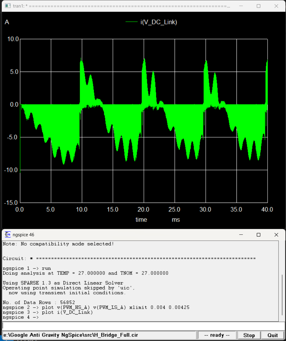 Negative current = energy delivery to load. Positive spikes at zero-crossings = inductive freewheeling through body diodes.
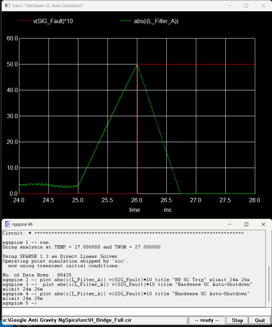 0.1Ω dead-short at t=25ms. CT + comparator trips INT0 latch at 50A primary. Current decays through freewheeling path within 1ms.
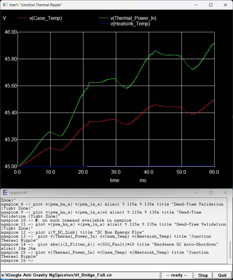 Foster RC network output. 50Hz thermal ripple at junction node. Heatsink stable at 45°C.
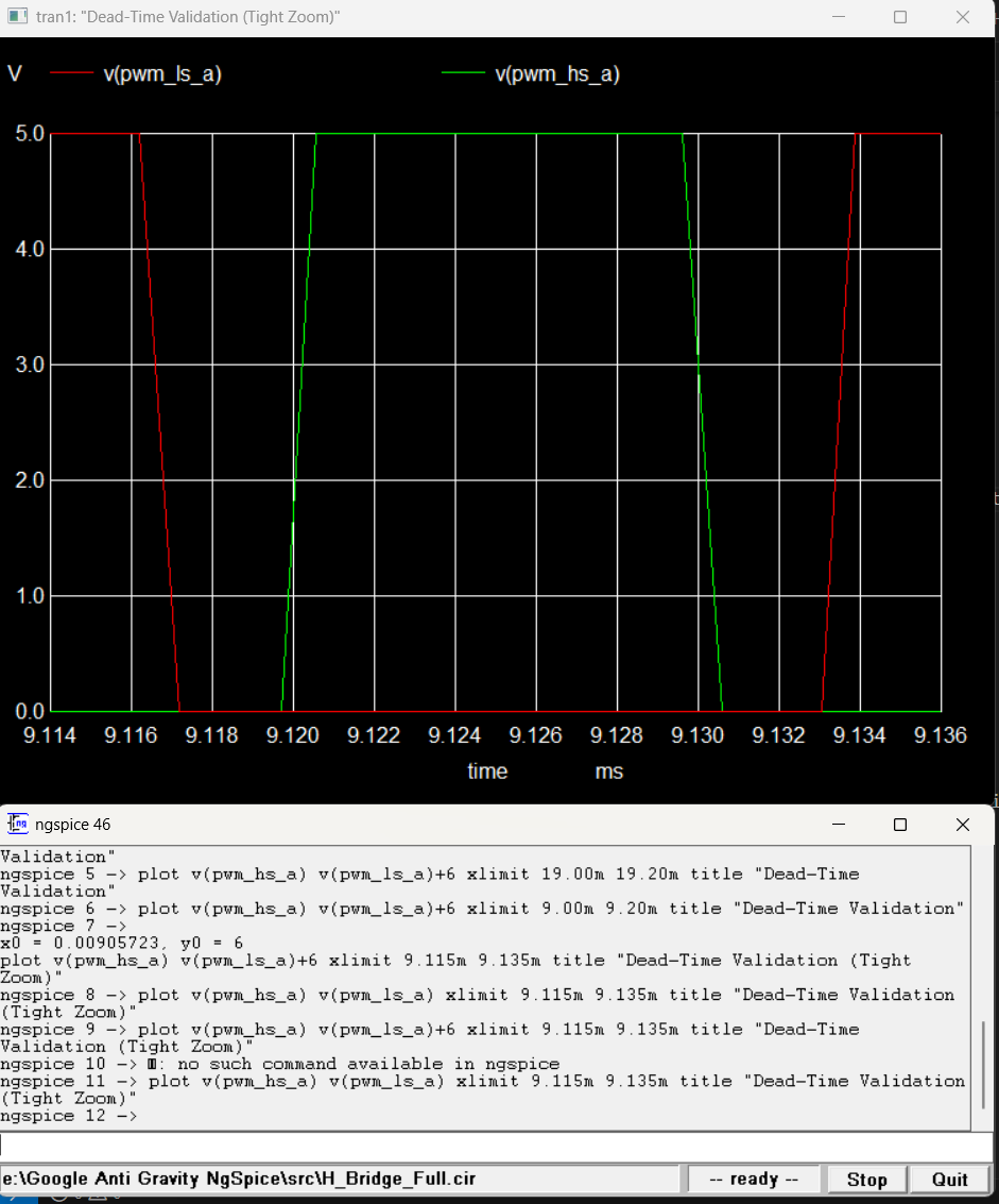 Single switching event: both gate signals at 0V for the full 2µs dead-time interval.
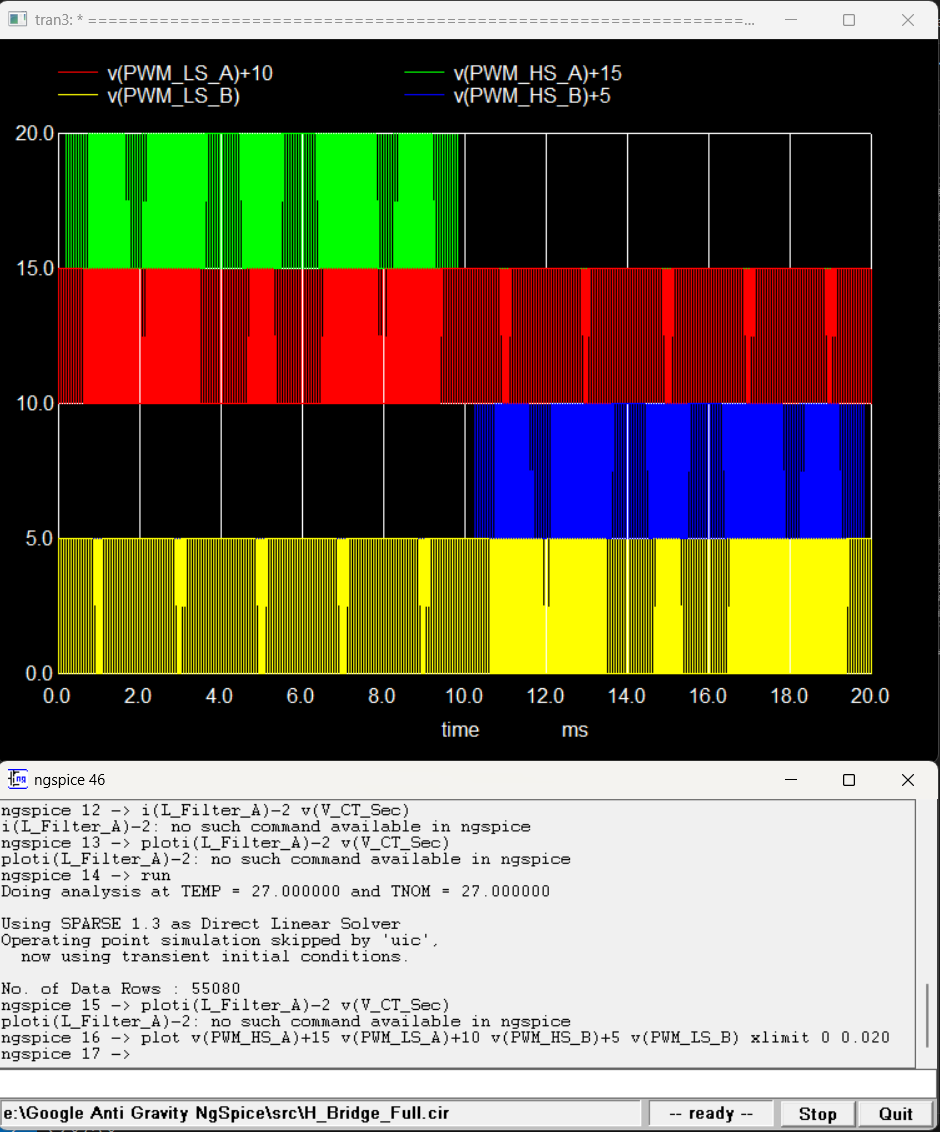 Full 20ms cycle. Leg A switches at 16kHz on the positive half; Leg B clamped. Roles exchange at zero-crossing.