
2 layers83.8 × 53.3 mm
Tester pcb business card unrouted
MarkJB/Tester_PCB_Business_Card
A PCB Business Card designed for and by a Tester (QA Engineer)
41 parts10

 MarkJB/Tester_PCB_Business_Card10
A PCB Business Card designed for and by a Tester (QA Engineer)
Tester pcb business card is an open-source printed circuit board by MarkJB, from the MarkJB/Tester_PCB_Business_Card repository on GitHub. It is a 2-layer board of 83.8 × 53.3 mm with 46 parts on 36 nets, routed with 392 tracks and 26 vias.
It is built around the CR2032. Its parts include 20 resistors, 15 diodes, 6 switches, 2 capacitors and 1 IC. It belongs with the RISC-V boards of this library.
A PCB Business Card designed by a tester, for testers (QA Engineers)
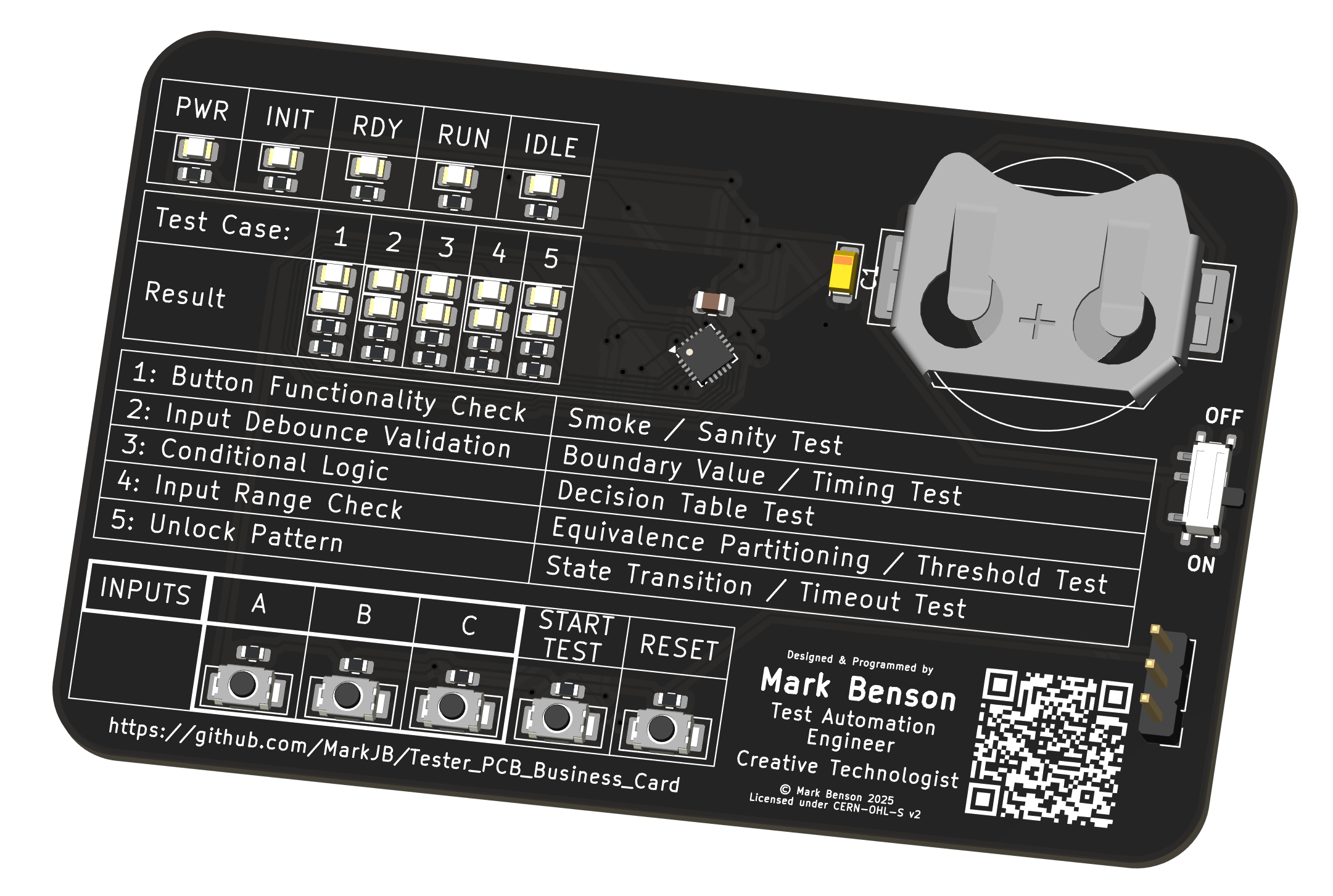
I've always liked the PCB business cards I've seen people design. They often have an interesting story about the why and the how, and sometimes even lead to a job offer as a result!
Note: For any recruiters or prospective employers who end up here, I'm a software tester specializing in WebUI test automation. Electronics and hardware is a hobby (and occasionally a freelance gig in the Creative Technologist/Arts and Technology space)
I wanted to give it a go but couldn't think of anything compelling that was related to my primary industry (QA, Software Testing & Test Automation). Then I saw a recent pong example on Hackaday which made me wonder whether the author had done much testing, and that sparked the idea of creating a PCB business card all about testing.
There are 5 'test cases'*, each one designed to be a little bit harder than the previous one and to focus on a different class of test. The hardware is somewhat limited, so how well each of the tests achieves its intended goal or how true it is to its test type is open for debate and I welcome feedback from actual testers!
The idea is that a tester should be able to look at the test case description, its test type and, given the available inputs and output, figure out how to get the tests to pass, treating it as a sort of black-box exploratory test session. Think of it as a fidget toy for tester.
That all said, I've not yet had any feedback from any testers so I don't know if its too easy or too hard. If you want to cheat, dig into this repo and you'll find the test case BDD scenarios and solutions (which I have deliberately not linked from any of the main READMEs), or as an alternative you can read the code (either the main firmware or the simulator should provide a white-box experience).
* I use the term "test cases" to refer to the tests that the hardware is presenting to the end user to 'execute', but in some places I have also created actual tests for the code as well (like the Playwright tests for the simulator).
Note: There may be minor differences between the simulator and the actual hardware due to implementation details or I changed direction while working on the firmware and haven't gotten round to updating the simulator.
So here is Rev A:
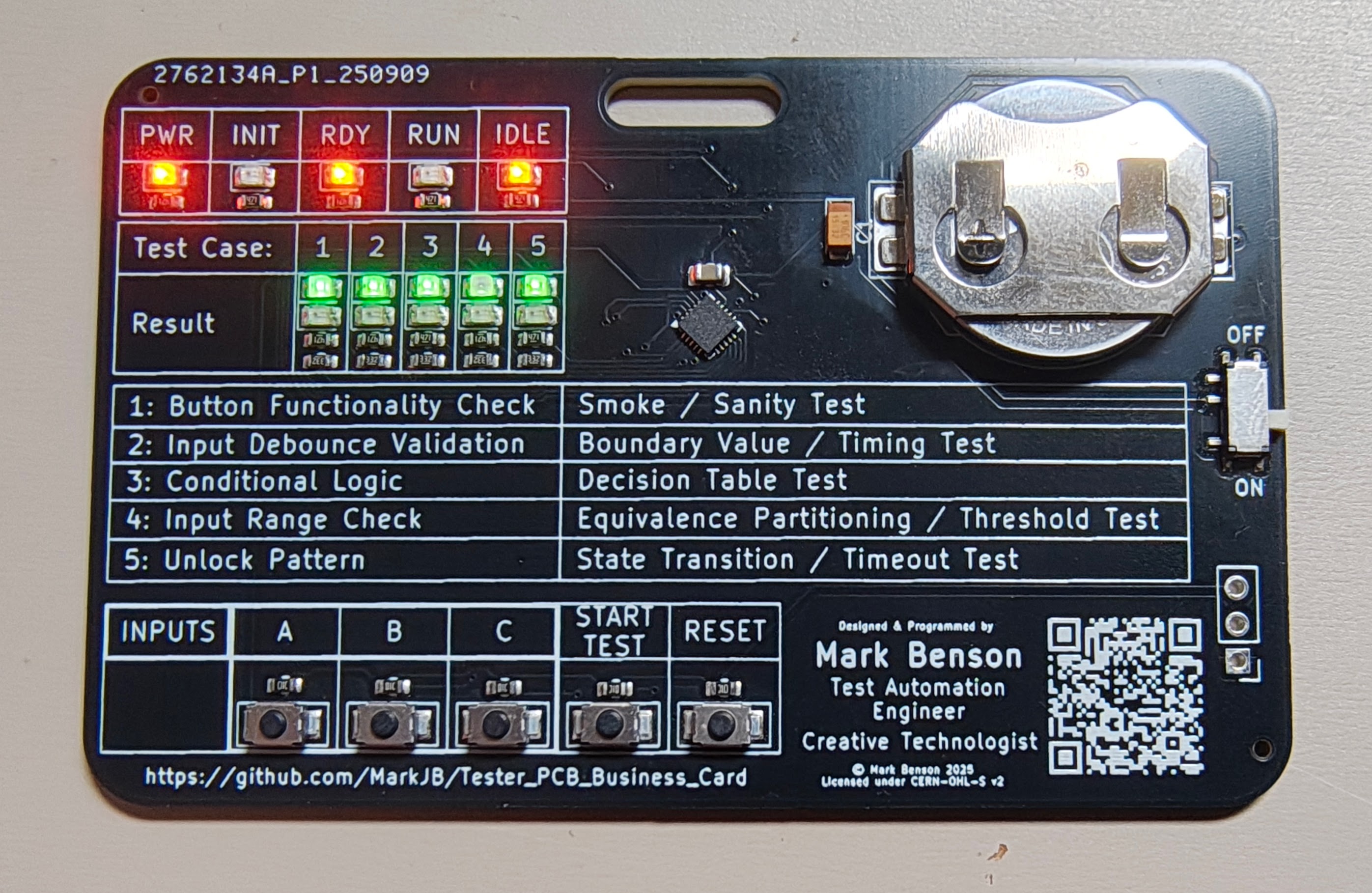
This is based on the CH32V003F4U6. A 27¢ micro controller with a one-wire programmer that costs less than $8. I had no experience with this when I started this project, but cost was a big factor with the card. I'm aiming for sub $2 per unit so I can a) afford to get a handful made and b) give them away at conferences and networking events.
Note: I added a slot for attaching to a lanyard as I intend to give these out at networking and conference events.
This repo includes:
The schematic, PCB design, BoM and JLCPCB ready production files Kicad 9 files here
Simulator README
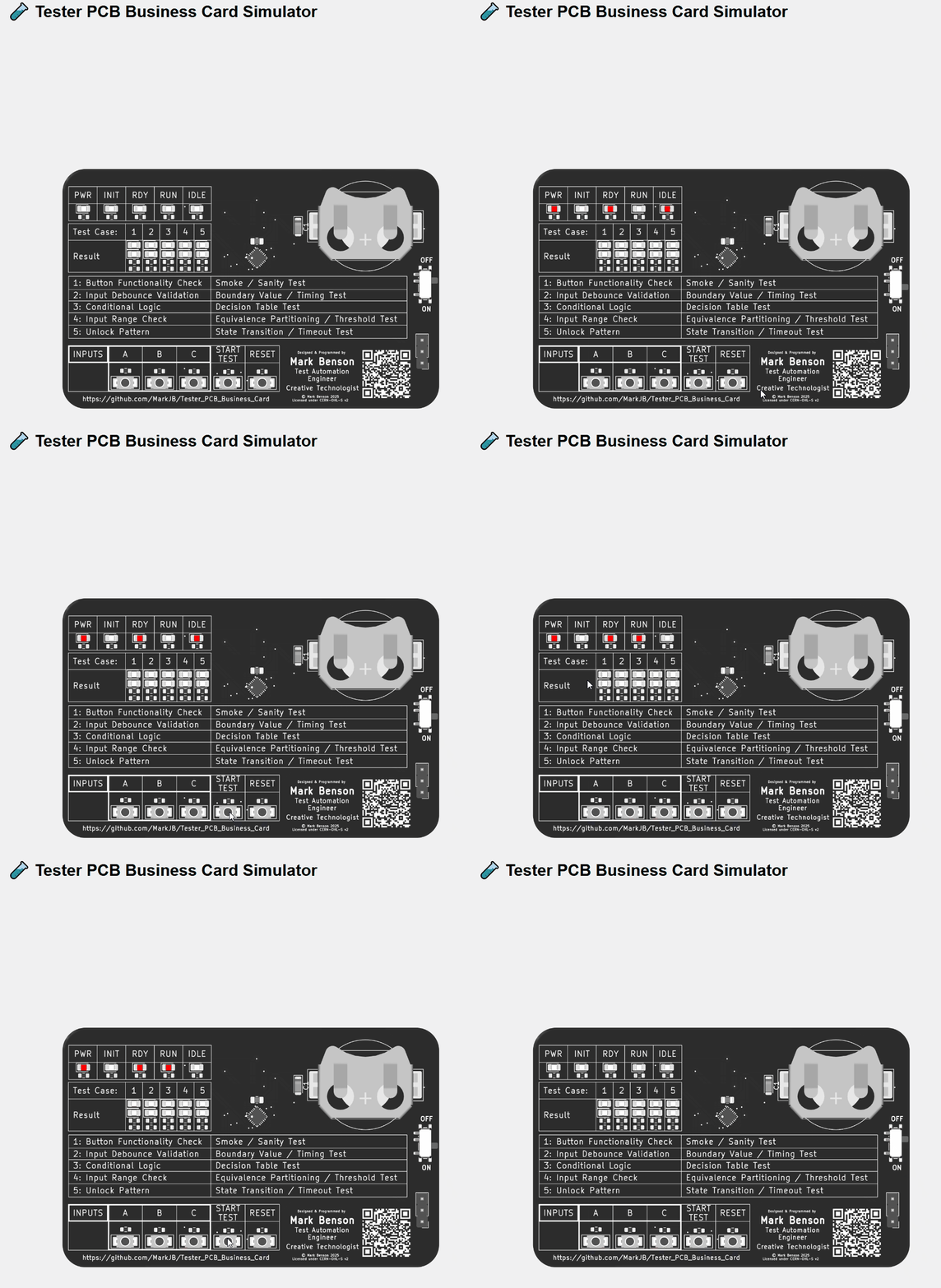
The simulator is built, tested and (if successful) deployed to GitHub pages by a GitHub Actions pipeline
You can play with the deployed simulator here: Simulator Demo
Uses platformio and the ch32fun framework.
Main firmware: The main firmware containing tests, test case runner, LED control, button functions etc.
Board check: Simple test firmware to confirm LEDs and buttons are connected and working. Mainly used for testing hand assembled prototype boards.
LED Tune: Simple firmware to allow manual tuning of resistor values. shouldn't need this again unless the LEDs are changed for ones that are significantly different.
Copyright Mark Benson 2025
The hardware is licensed under the CERN-OHL-S v2 license. The software is licensed under the MIT license.
Usual disclaimer - No warranty implied or given for any use or outcome of any of the available materials, etc.
This isn't a toy, it's not suitable for children. As it's not in a case, there is a risk of short circuiting the components and battery, resulting in damage or overheating, so do not put it in your pocket or bag or anywhere where metal objects could cause short circuit. Note: Battery should be inserted + side up. Incorrectly inserted battery will short out resulting in damage or overheating. Use at your own risk.
| Qty | Value | Footprint | References |
|---|---|---|---|
| 10 | 470 | Resistor_SMD:R_0603_1608Metric | R1, R2, R3, R4, R5, R11, R13, R15, R17, R19 |
| 5 | 10k | Resistor_SMD:R_0603_1608Metric | R6, R7, R8, R9, R10 |
| 5 | 3.3k | Resistor_SMD:R_0603_1608Metric | R12, R14, R16, R18, R20 |
| 2 | IDLE | LED_SMD:LED_0805_2012Metric | D5, D13 |
| 1 | 0.1u | Capacitor_SMD:C_0805_2012Metric | C2 |
| 1 | 10u | Capacitor_Tantalum_SMD:CP_EIA-3216-18_Kemet-A | C1 |
| 1 | A | custom:BTN_XUNPU_TS_1088-AR02016 | SW2 |
| 1 | B | custom:BTN_XUNPU_TS_1088-AR02016 | SW3 |
| 1 | C | custom:BTN_XUNPU_TS_1088-AR02016 | SW4 |
| 1 | CH32V003FxUx | Package_DFN_QFN:QFN-20-1EP_3x3mm_P0.4mm_EP1.65x1.65mm | U1 |
| 1 | CR2032 | custom:MY-2032-12 | BT1 |
| 1 | D | custom:BTN_XUNPU_TS_1088-AR02016 | SW5 |
| 1 | INIT | LED_SMD:LED_0805_2012Metric | D2 |
| 1 | PWR | LED_SMD:LED_0805_2012Metric | D1 |
| 1 | PWR | custom:SW_SPDT_Shouhan_MSK12C02 | SW1 |
| 1 | RA_G | LED_SMD:LED_0805_2012Metric | D11 |
| 1 | RA_R | LED_SMD:LED_0805_2012Metric | D6 |
| 1 | RB_G | LED_SMD:LED_0805_2012Metric | D12 |
| 1 | RB_R | LED_SMD:LED_0805_2012Metric | D7 |
| 1 | RC_R | LED_SMD:LED_0805_2012Metric | D8 |
| 1 | RDY | LED_SMD:LED_0805_2012Metric | D3 |
| 1 | RD_G | LED_SMD:LED_0805_2012Metric | D14 |
| 1 | RD_R | LED_SMD:LED_0805_2012Metric | D9 |
| 1 | RE_G | LED_SMD:LED_0805_2012Metric | D15 |
| 1 | RE_R | LED_SMD:LED_0805_2012Metric | D10 |
| 1 | RST | custom:BTN_XUNPU_TS_1088-AR02016 | SW6 |
| 1 | RUN | LED_SMD:LED_0805_2012Metric | D4 |
| 1 | SWIO | Connector_PinHeader_2.54mm:PinHeader_1x03_P2.54mm_Vertical | J1 |
MarkJB/Tester_PCB_Business_Card
A PCB Business Card designed for and by a Tester (QA Engineer)


skiselev/zeta_sbc
Zeta SBC is an Zilog Z80 based single board computer. It is inspired by Ampro Little Board Z80 and N8VEM project. Zeta SBC is software compatible with RomWBW Firmware
It measures 83.8 × 53.3 mm and has 2 copper layers, 1.6 mm thick.
46 parts, built around the CR2032. The full list of its parts is on this page, with links to each part's symbol and footprint where PCBKit's library has them.
From the MarkJB/Tester_PCB_Business_Card repository on GitHub, at the commit this page was made from: the board is hardware/tester_pcb_business_card.kicad_pcb and its schematic hardware/tester_pcb_business_card.kicad_sch. PCBKit opens the board in the browser, with nothing to install.
Its repository states no licence, so its author keeps all rights: ask MarkJB before reusing the design.