Skip to the content
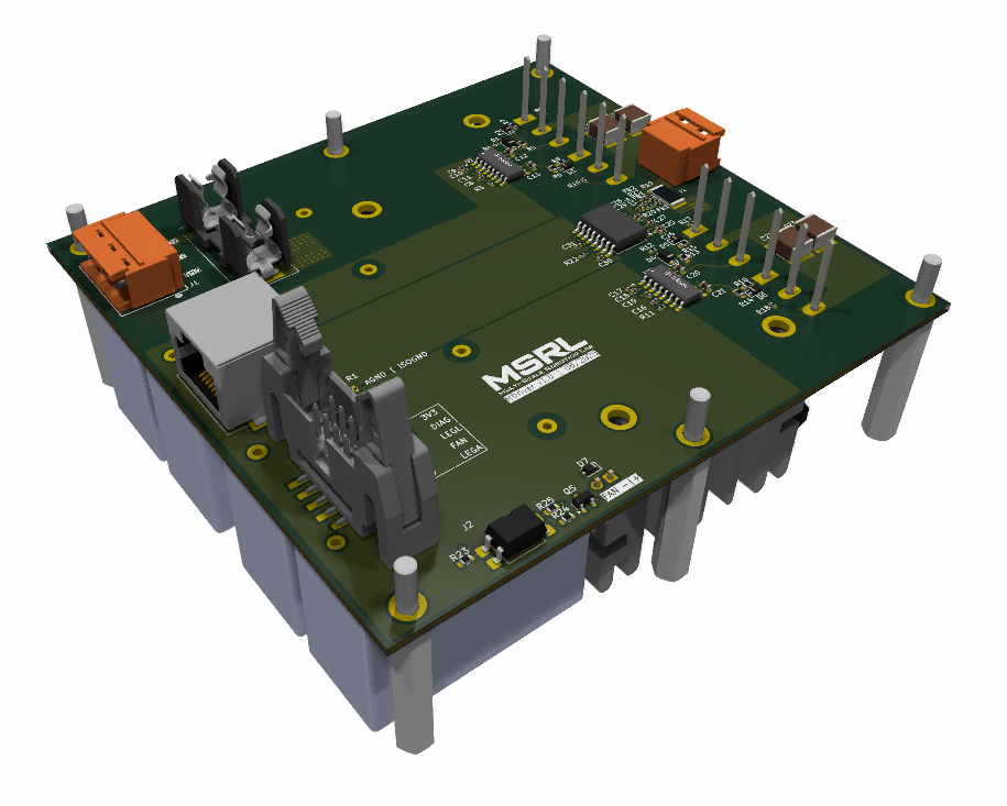
4 layers115 × 108 mmMdriver hw power, the printed circuit board in 3D

Mdriver hw power

MagnebotiX/mdriver2_hw

Hardware Repository for `mdriver2`

Size
115 × 108 mm
Copper layers
4
Thickness
1.6 mm
Parts
94
Nets
55
Pads
246
Tracks, vias
364, 131
Pours
19
Routed
Yes
KiCad
KiCad 9.0 (file 20241229)
Created
24 Oct 2025
Updated
16 Oct 2025

Overview

Mdriver hw power is an open-source printed circuit board by MagnebotiX, from the MagnebotiX/mdriver2_hw repository on GitHub. It is a 4-layer board of 115 × 108 mm with 94 parts on 55 nets, routed with 364 tracks and 131 vias.

It is built around the SFH617A-1X007T and BC817. Its parts include 34 capacitors, 27 resistors, 7 diodes, 6 switches and 5 transistors.

Main components

2

README

readme.md

MDriver2 Hardware

This repository contains the hardware design files of the MDriver2 project.

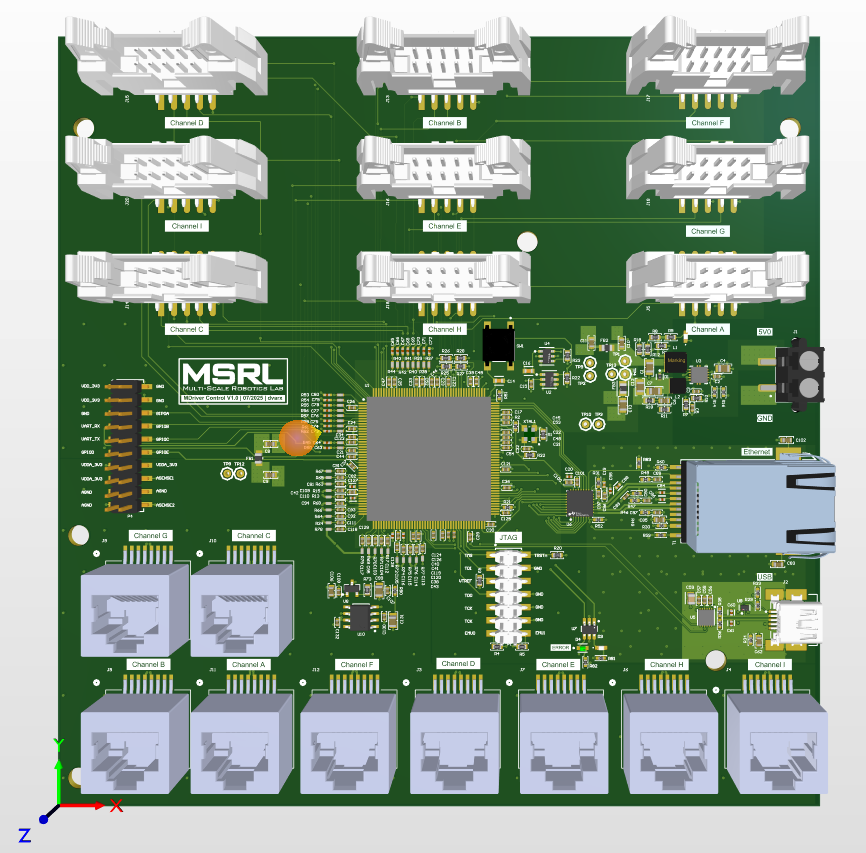
Control Hardware

alt text

Power Hardware

alt text

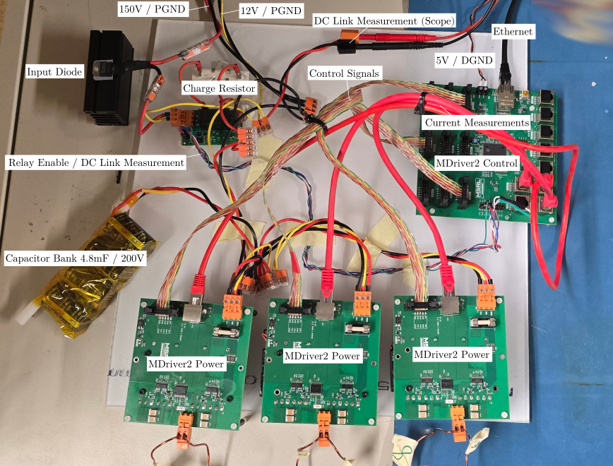
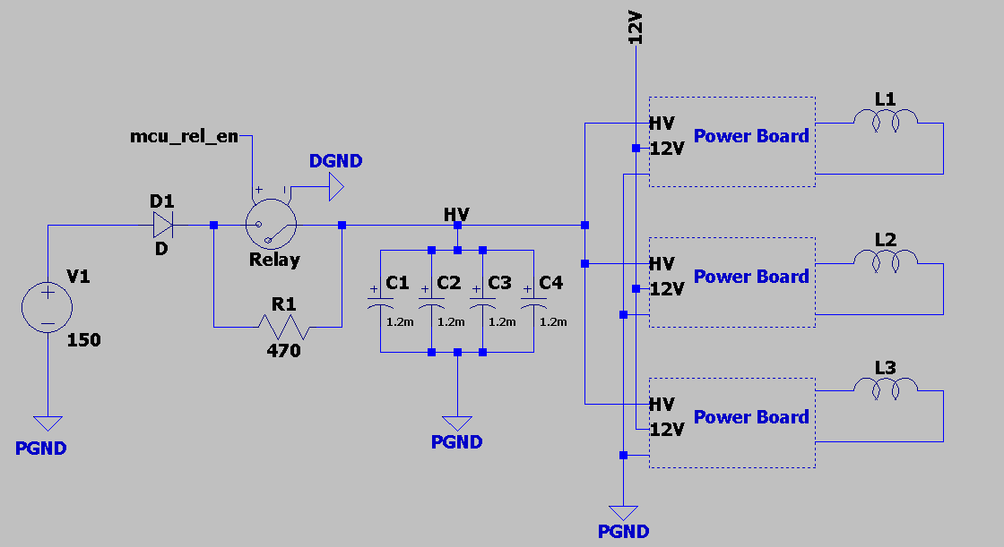
Experimental Setup Overview

alt text alt text

  • The input diode D1 is optional and used to protect the supply V1.
  • The charge resistor R1 is used to limit excessive inrush current to the capcacitor bank but may not be needed for all supplies.
  • The DC link voltage VH is monitored using an isolated DC measurement from the capbank PCB. Voltage values are transmitted via delta-sigma modulation to the microcontroller.

Parts

94
QtyValueFootprintReferences
12100nFCapacitor_SMD:C_0402_1005MetricC6, C8, C11, C16, C19, C26, C27, C29, C30, C31, C32, C33
62.2uCapacitor_SMD:C_0603_1608MetricC7, C12, C13, C20, C21, C34
6Hex Spacer 25mmmdriver:hex_spacerS1, S2, S3, S4, S5, S6
5D_SchottkyDiode_SMD:D_SOD-323FD2, D3, D5, D6, D7
4100pFCapacitor_SMD:C_0402_1005MetricC9, C10, C17, C18
41uCapacitor_SMD:C_2220_5750Metric_Pad1.97x5.40mm_HandSolderC14, C15, C22, C23
425uFmdriver:film_cap_25uFC1, C2, C3, C4
43.3Resistor_SMD:R_0603_1608MetricR6, R8, R14, R16
4560kResistor_SMD:R_0402_1005MetricR9, R10, R17, R18
4NMOSPackage_TO_SOT_THT:TO-247-3_VerticalQ1, Q2, Q3, Q4
32.2OhmInductor_SMD:L_0402_1005MetricFB1, FB2, FB3
3430Resistor_SMD:R_0603_1608MetricR23, R24, R25
20Resistor_SMD:R_0402_1005MetricR3, R11
20Resistor_SMD:R_0603_1608MetricR5, R13
210Resistor_SMD:R_0402_1005MetricR20, R21
212Resistor_SMD:R_0603_1608MetricR7, R15
218Resistor_SMD:R_1206_3216MetricR4, R12
21uCapacitor_SMD:C_0402_1005MetricC24, C25
22EDB8259Ymdriver:SOIC-16U1, U2
268kResistor_SMD:R_2512_6332MetricR26, R27
2DDiode_SMD:D_SOD-123FD1, D4
11MegResistor_SMD:R_0402_1005MetricR2
11nFCapacitor_SMD:C_0402_1005MetricC28
147kResistor_SMD:R_0402_1005MetricR22
15mResistor_SMD:R_2512_6332Metric_Pad1.40x3.35mm_HandSolderR19
1BC817Package_TO_SOT_SMD:SOT-23Q5
1CCapacitor_SMD:C_0402_1005MetricC5
1Conn_01x02mdriver:weidmuller_20A_2pinJ4
1Conn_02x05_Odd_Evenmdriver:10pin_data_connectorJ2
1FanConnector_PinHeader_2.54mm:PinHeader_1x02_P2.54mm_VerticalM1
1Fusemdriver:fuseF1
1Heatsink_Padmdriver:heatsink_assmanHS1
1LOGOmdriver:msrl_logoG***
1RResistor_SMD:R_0402_1005MetricR1
1SFH617A-1X007TPackage_DIP:SMDIP-4_W9.53mm_Clearance8mmU4
1~mdriver:CONN_1148070000_WEDJ1
1~mdriver:J_Wurth_WR-MJ_634008149821J3
1~mdriver:AMC3302DWERU3

Similar boards

  • 2 layers80 × 66 mmPeriph, the printed circuit board in 3D

    Periph

    bastien313/Open-test-bench

    Open test bench is an open-source platform for drive or characterize any type of system. The system is made for simplifying the development of additional modules called "peripheral module".

    46 parts6GPL-3.0
  • 2 layers158.4 × 98.8 mmMotor driver, the printed circuit board in 3D

    Motor driver

    hex-inverter/VVVF_motor_drive

    The inspiration for this project came from a very characteristic sound in Amsterdam metro trams. During acceleration or braking they make a "shifting gears" sound even though the motors are electric (this sound can also…

    68 parts1
  • 4 layers59 × 7.1 mmUHoubolt PCB PMU, the printed circuit board in 3D

    UHoubolt PCB PMU

    SpaceTeam/uHoubolt_PCB_PMU

    µHoubolt Power Management Unit KiCad project

    166 partsCERN-OHL-W-2.0
  • 2 layers88.9 × 82.6 mmReflowplate, the printed circuit board in 3D

    Reflowplate

    xLordiz3/PCBs

    44 parts
  • 2 layers72 × 42 mmNRF24 jammer, the printed circuit board in 3D

    NRF24 jammer

    W0rthlessS0ul/nRF24_jammer

    The nRF24 jammer is a powerful tool that requires an ESP32 and configurable numbers of NRF24 modules to assemble.

    51 parts1kMIT
  • 2 layers271.8 × 114.3 mmArdumower mega shield svn, the printed circuit board in 3D

    Ardumower mega shield svn

    Ardumower/ardumower

    Develop an open source robotic lawn mower (HW+SW reference platform)

    426 parts282
  • 2 layers65 × 56.5 mmRPiG3iMac, the printed circuit board in 3D

    RPiG3iMac

    qbancoffee/imac_g3_ivad_board_init

    iMac G3 IVAD board initialization with an arduino

    44 parts240LGPL-3.0
  • 6 layers83.5 × 56 mmEspiff v3 1, the printed circuit board in 3D

    Espiff v3 1

    MDCservice/EsPiFF

    An ESP32 in the Raspberry Pi form factor

    172 parts223GPL-3.0

Questions

How big is the Mdriver hw power PCB?

It measures 115 × 108 mm and has 4 copper layers, 1.6 mm thick.

What parts does the Mdriver hw power use?

94 parts, built around the SFH617A-1X007T and BC817. The full list of its parts is on this page, with links to each part's symbol and footprint where PCBKit's library has them.

Where can I download the Mdriver hw power KiCad files?

From the MagnebotiX/mdriver2_hw repository on GitHub, at the commit this page was made from: the board is kicad_power/mdriver_hw_power.kicad_pcb and its schematic kicad_power/fan.kicad_sch. PCBKit opens the board in the browser, with nothing to install.

Can I use the Mdriver hw power design in my own project?

Its repository states no licence, so its author keeps all rights: ask MagnebotiX before reusing the design.