4 layers94 × 81.8 mm
ESP32 IO Controller
Satya777777/ESP32-Industrial-IO-Controller
4-layer ESP32-based industrial I/O controller designed in KiCad with 0–10 V, 4–20 mA, RS485, USB-C and relay interfaces.
58 partsMIT
 Maczla/Raspberry_Pi_Pico_Automotive_Interface
Automotive interface board for Raspberry Pi Pico with 12 V power protection, vehicle signal inputs, SWC analog inputs and configurable PWM output.
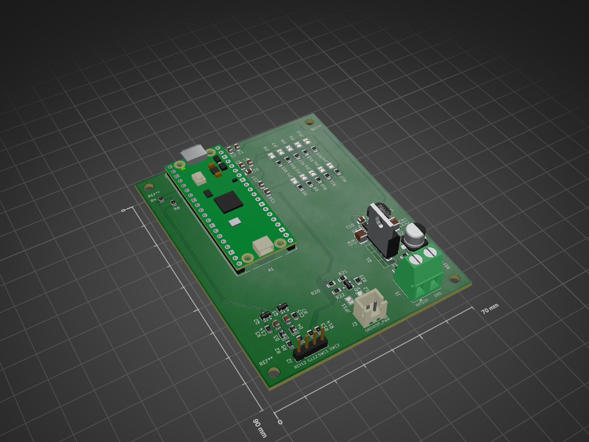
CarBoard Raspberry PiPico is an open-source printed circuit board by Maczla, from the Maczla/Raspberry_Pi_Pico_Automotive_Interface repository on GitHub, published under the MIT licence. It is a 2-layer board of 70 × 90 mm with 72 parts on 59 nets, routed with 320 tracks and 16 vias.
It is built around the AP63205WU, MMBT3904 and BZV55B12, with the ESD9B3.3ST5G, FQP27P06 and PTVS26VZ1USK among its other parts. Its parts include 23 resistors, 17 capacitors, 5 diodes, 4 transistors and 3 connectors. It belongs with the interfaces and adapters boards and the RP2040 boards of this library.


This project is a custom automotive interface board designed around the Raspberry Pi Pico (RP2040). It enables safe integration of the microcontroller with a standard 12 V vehicle electrical system by providing power conversion, input signal conditioning, protection circuits, and configurable PWM output.
The board was designed entirely from scratch in KiCad 9, following recommended PCB layout practices for switching power supplies and automotive electronics.
The project includes complete design files, production-ready Gerber files, BOM, and manufacturing documentation.
| Component | Part Number |
|---|---|
| MCU Module | Raspberry Pi Pico |
| Buck Converter | AP63205WU-7 |
| Input TVS | PTVS26VZ1USKYL |
| Reverse Polarity MOSFET | FQP27P06 |
| PWM MOSFET | 2N7002 |
| Input Transistor | MMBT3904 |
| Power Inductor | ASPI-0630LR-4R7M-T15 |
Hardware/
Documentation/
Gerbers/
Images/
README.md
LICENSE(Insert schematic image here)
(Insert PCB top view here)
(Insert 3D render here)
The repository includes:
Designed using:
Maciej Zaczyk
This project is released under the MIT License.
| Qty | Value | Footprint | References |
|---|---|---|---|
| 10 | 100nF | Capacitor_SMD:C_0805_2012Metric | C1, C4, C5, C6, C10, C13, C14, C15, C16, C17 |
| 5 | 10k | Resistor_SMD:R_0805_2012Metric | R4, R6, R10, R17, R22 |
| 4 | 100k | Resistor_SMD:R_0805_2012Metric | R1, R3, R7, R23 |
| 3 | 10uF | Capacitor_SMD:C_0805_2012Metric | C2, C3, C9 |
| 2 | 100 | Resistor_SMD:R_0805_2012Metric | R20, R21 |
| 2 | 15k | Resistor_SMD:R_0805_2012Metric | R11, R18 |
| 2 | 1k | Resistor_SMD:R_0805_2012Metric | R13, R14 |
| 2 | 22k | Resistor_SMD:R_0805_2012Metric | R12, R19 |
| 2 | 22uF / 16V | Capacitor_SMD:C_1210_3225Metric | C11, C12 |
| 2 | 4,7k | Resistor_SMD:R_0805_2012Metric | R8, R15 |
| 2 | 47k | Resistor_SMD:R_0805_2012Metric | R2, R5 |
| 2 | 6,8k | Resistor_SMD:R_0805_2012Metric | R9, R16 |
| 2 | D_Small | Diode_SMD:D_0805_2012Metric | D3, D4 |
| 2 | MMBT3904 | Package_TO_SOT_SMD:SOT-23 | Q2, Q3 |
| 1 | 100nF | Capacitor_SMD:C_1210_3225Metric | C8 |
| 1 | 100uF / 35V | Capacitor_SMD:CP_Elec_6.3x5.9 | C7 |
| 1 | 2N7002 | Package_TO_SOT_SMD:SOT-23 | Q4 |
| 1 | 3A | Fuse:Fuse_1206_3216Metric | F1 |
| 1 | 4.7uH | Inductor_SMD:L_6.3x6.3_H3 | L1 |
| 1 | AP63205WU | Package_TO_SOT_SMD:TSOT-23-6 | U1 |
| 1 | BZV55B12 | Diode_SMD:D_MiniMELF | D2 |
| 1 | DISPLAY_PWM_OUT | Connector_JST:JST_XH_B2B-XH-A_1x02_P2.50mm_Vertical | J3 |
| 1 | ESD9B3.3ST5G | Diode_SMD:D_SOD-923 | D5 |
| 1 | FQP27P06 | Package_TO_SOT_THT:TO-220-3_Vertical | Q1 |
| 1 | OPEN-DRAIN | Jumper:SolderJumper-2_P1.3mm_Open_TrianglePad1.0x1.5mm | JP12 |
| 1 | PTVS26VZ1USK | Diode_SMD:Nexperia_DSN1608-2_1.6x0.8mm | D1 |
| 1 | PUSH-PULL | Jumper:SolderJumper-2_P1.3mm_Open_TrianglePad1.0x1.5mm | JP11 |
| 1 | RaspberryPi_Pico | Module:RaspberryPi_Pico_Common_THT | A1 |
| 1 | SWC1_10K | Jumper:SolderJumper-2_P1.3mm_Open_TrianglePad1.0x1.5mm | JP3 |
| 1 | SWC1_15K | Jumper:SolderJumper-2_P1.3mm_Open_TrianglePad1.0x1.5mm | JP4 |
| 1 | SWC1_22K | Jumper:SolderJumper-2_P1.3mm_Open_TrianglePad1.0x1.5mm | JP5 |
| 1 | SWC1_4K7 | Jumper:SolderJumper-2_P1.3mm_Open_TrianglePad1.0x1.5mm | JP1 |
| 1 | SWC1_6K8 | Jumper:SolderJumper-2_P1.3mm_Open_TrianglePad1.0x1.5mm | JP2 |
| 1 | SWC2_10K | Jumper:SolderJumper-2_P1.3mm_Open_TrianglePad1.0x1.5mm | JP8 |
| 1 | SWC2_15K | Jumper:SolderJumper-2_P1.3mm_Open_TrianglePad1.0x1.5mm | JP9 |
| 1 | SWC2_22K | Jumper:SolderJumper-2_P1.3mm_Open_TrianglePad1.0x1.5mm | JP10 |
| 1 | SWC2_4K7 | Jumper:SolderJumper-2_P1.3mm_Open_TrianglePad1.0x1.5mm | JP6 |
| 1 | SWC2_6K8 | Jumper:SolderJumper-2_P1.3mm_Open_TrianglePad1.0x1.5mm | JP7 |
| 1 | VEHICLE_SIGNALS | Connector_PinHeader_2.54mm:PinHeader_1x04_P2.54mm_Vertical | J2 |
| 1 | Vehicle Power | TerminalBlock_Phoenix:TerminalBlock_Phoenix_MKDS-1,5-2-5.08_1x02_P5.08mm_Horizontal | J1 |
The 68 most common of 72 parts.
Satya777777/ESP32-Industrial-IO-Controller
4-layer ESP32-based industrial I/O controller designed in KiCad with 0–10 V, 4–20 mA, RS485, USB-C and relay interfaces.


defGonzaloR/ESRA-RUDynamics-Board
V3 of a power distribution board prototype, implementing signal filtering for Jetson implementation and overal signal integrity.

Emanuel600/Spotcar-Inversora
Project repo for the inverter spotcar prototype - from board to code


RoboJackets/roboracing-micromouse-pcb
This year, we are making Ratatouillii! 🐭🔥

It measures 70 × 90 mm and has 2 copper layers, 1.6 mm thick.
72 parts, built around the AP63205WU, MMBT3904, BZV55B12 and ESD9B3.3ST5G. The full list of its parts is on this page, with links to each part's symbol and footprint where PCBKit's library has them.
From the Maczla/Raspberry_Pi_Pico_Automotive_Interface repository on GitHub, at the commit this page was made from: the board is KiCad/CarBoard_Raspberry PiPico.kicad_pcb and its schematic KiCad/CarBoard_Raspberry PiPico.kicad_sch. PCBKit opens the board in the browser, with nothing to install.
Its repository publishes it under the MIT licence: you may reuse it on that licence's terms (keep the author's notice, and for a copyleft licence share your changes alike).