2 layers65 × 30 mm
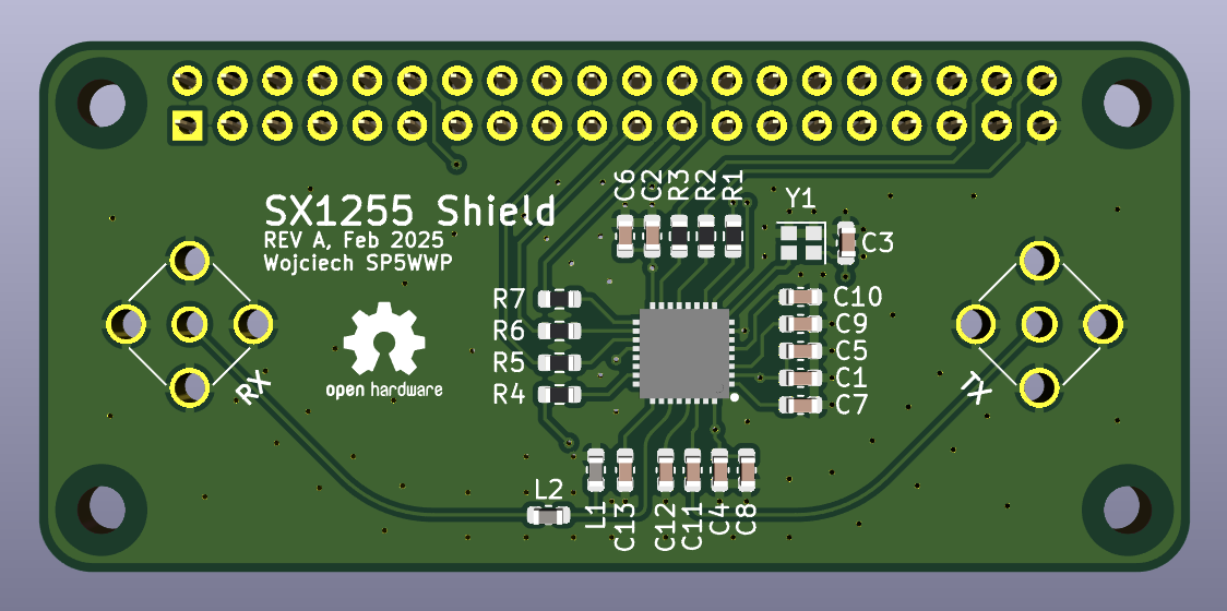
SX1255 HAT
Jankyneering/SX1255_dev_hat
Raspberry Pi Zero shield with the SX1255 RF transceiver chip. Based on M17's design.
42 parts2CC-BY-SA-4.0

 M17-Project/SX1255_HAT-hw47
Raspberry Pi Zero shield with the SX1255 RF transceiver chip
SX1255 HAT hw is an open-source printed circuit board by M17-Project, from the M17-Project/SX1255_HAT-hw repository on GitHub. It is a 2-layer board of 65 × 30 mm with 32 parts on 64 nets, routed with 154 tracks and 91 vias.
It is built around the SX1255IWLTRT, CRCW0603100RFKECC and 06035G104ZAT2A, with the C0603C103M4REC7411, AC0603JRNPO9BN270 and ECS-TXO-20CSMV4-320-AY-TR among its other parts. Its parts include 13 capacitors, 7 resistors, 3 connectors, 2 inductors and 1 IC. It belongs with the radio and wireless boards of this library.


Raspberry Pi Zero shield with the SX1255 RF transceiver chip.
[!NOTE] In case the TCXO used in the project is not available,
TG2016SMN 32.0000M-MCGNNM0is a valid replacement (0.5ppm frequency stability). Alternatively,ECS-TXO-20CSMV-320-EYcan be used (2.5ppm frequency stability).
| Parameter | Value |
|---|---|
| Tuning range | 400 to 510MHz (356 to 562MHz out-of-spec) |
| RF output power | +5dBm typ. (1dB compression point) |
| Baseband interface | I2S (master) |
| Frequency synthesizer step size | ~30.5Hz |
| RX gain range | 70dB |
See the SX1255 datasheet for more detaiils.
Sample Raspberry Pi code for SX1255 control can be found here.
I2S slave overlay is required. Sample rate for both RX and TX can be set to 125, 250, or 500kHz.
RX/TX frequency setting (500kHz sample rate):
./sx1255-spi -s 500 -r 435000000 -t 438000000arecord -t raw -f S32_LE -r 192000 -c 2 --device="hw:0,1" | ./int_to_short | ./zmq-pubIn which int_to_short is a simple int to short format converter:
while(1)
{
  ioctl(STDIN_FILENO, FIONREAD, &rcvd);
  if(rcvd>0)
  {
    if(read(STDIN_FILENO, inp, rcvd)==rcvd)
    {
      for(int i=0; i<rcvd; i+=8)
      {
        memcpy(&out[i/2  ], &inp[i  +2], 2);
        memcpy(&out[i/2+2], &inp[i+4+2], 2);
      }

      write(STDOUT_FILENO, out, rcvd/2);
    }
  }
}./zmq-sub 192.168.50.243:17018 | aplay -t raw -f S32_LE -r 192000 -c 2 --device="hw:0,0"There are 2 demo flowgraphs available:
The RX demo also provides a set of sinc compensating FIR filter taps through the Decimating FIR Filter block.
This work is licensed under a Creative Commons Attribution-NonCommercial-ShareAlike 4.0 International License.

| Qty | Value | Footprint | References |
|---|---|---|---|
| 7 | 100R | Resistor_SMD:R_0603_1608Metric | R1, R2, R3, R4, R5, R6, R7 |
| 7 | 100n | Capacitor_SMD:C_0603_1608Metric | C5, C6, C7, C8, C9, C10, C13 |
| 4 | 10n | Capacitor_SMD:C_0603_1608Metric | C1, C2, C3, C4 |
| 4 | MountingHole | MountingHole:MountingHole_2.7mm_M2.5_DIN965 | H1, H2, H3, H4 |
| 1 | 27p | Capacitor_SMD:C_0603_1608Metric | C12 |
| 1 | 32MHz | Crystal:Crystal_SMD_2016-4Pin_2.0x1.6mm | Y1 |
| 1 | 33p | Capacitor_SMD:C_0603_1608Metric | C11 |
| 1 | 39n | Inductor_SMD:L_0603_1608Metric | L2 |
| 1 | 82n | Inductor_SMD:L_0603_1608Metric | L1 |
| 1 | Logo_Open_Hardware_Small | Symbol:OSHW-Logo2_7.3x6mm_SilkScreen | SYM1 |
| 1 | RPi Zero | Connector_PinSocket_2.54mm:PinSocket_2x20_P2.54mm_Vertical | J3 |
| 1 | RX_SMA | Connector_Coaxial:SMA_Amphenol_901-144_Vertical | J2 |
| 1 | SX1255 | parts:QFN50P500X500X80-33N-D | IC1 |
| 1 | TX_SMA | Connector_Coaxial:SMA_Amphenol_901-144_Vertical | J1 |
Jankyneering/SX1255_dev_hat
Raspberry Pi Zero shield with the SX1255 RF transceiver chip. Based on M17's design.


fred-corp/pico-ice-bot
A simple robot chassis bot for the Pico-ICE FPGA dev board.


labdvm/SX1255-Tetra-TMO-HS-HAT
Modified sdr transciever for digital and analog modes include Tetra-TMO

It measures 65 × 30 mm and has 2 copper layers, 1.6 mm thick.
32 parts, built around the SX1255IWLTRT, CRCW0603100RFKECC, 06035G104ZAT2A and C0603C103M4REC7411. The full list of its parts is on this page, with links to each part's symbol and footprint where PCBKit's library has them.
From the M17-Project/SX1255_HAT-hw repository on GitHub, at the commit this page was made from: the board is SX1255_HAT-hw.kicad_pcb and its schematic SX1255_HAT-hw.kicad_sch. PCBKit opens the board in the browser, with nothing to install.
Its repository states no licence, so its author keeps all rights: ask M17-Project before reusing the design.