2 layers8.5 × 41 mm
 M17-Project/LinHT-hw221
LinHT - Linux-based, SDR handheld transceiver.
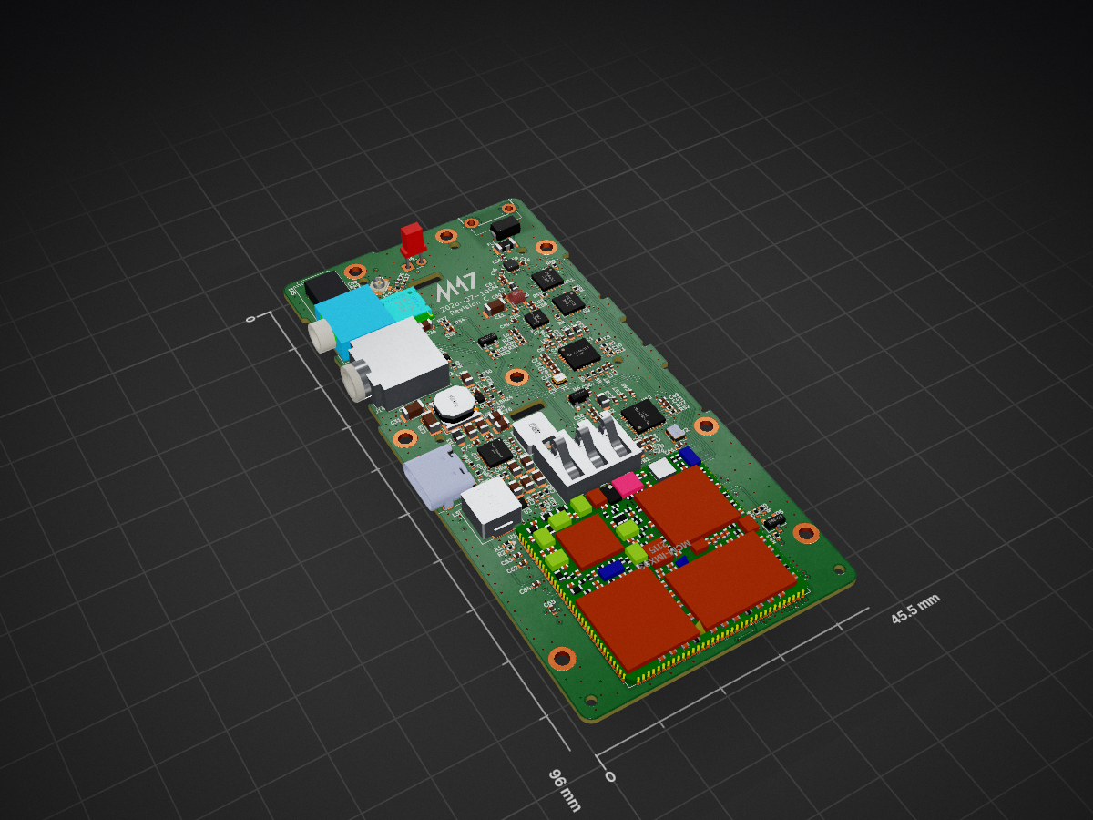
Linht hw is an open-source printed circuit board by M17-Project, from the M17-Project/LinHT-hw repository on GitHub. It is a 6-layer board of 45.5 × 96 mm with 258 parts on 301 nets, routed with 1,823 tracks and 673 vias.
It is built around the ATTINY826-MU, PE4312C-Z and BQ25792RQMR, with the GRF5604, CL21A106KBYQNNE and CC0402JRNPO9BN102 among its other parts. Its parts include 95 capacitors, 63 resistors, 12 connectors, 9 inductors and 5 ICs. It belongs with the radio and wireless boards and the AVR (ATmega, ATtiny) boards of this library.


A small side PCB for the LinHT handheld transceiver, carrying the two side buttons (PTT area) of the radio.
The board is soldered edge-on (perpendicularly) to the side of the LinHT main PCB. Its outline matches the original side-button board of the Retevis C62 donor radio, so it fits the stock enclosure and rubber button covers without modifications.
Apart from the PCB itself you need:
The domes are placed over the exposed button contacts and held in place by adhesive tape or the button membrane.
Gerber files are generated by the CI and published on the
LinHT hardware page, or can be exported
locally from side-pcb.kicad_pcb with KiCad 10.
| Qty | Value | Footprint | References |
|---|---|---|---|
| 33 | 100n | Capacitor_SMD:C_0402_1005Metric | C5, C10, C13, C21, C22, C23, C24, C25, C32, C33, C34, C35, C38, C49, C57, C59 +17 |
| 16 | 100k | Resistor_SMD:R_0402_1005Metric | R3, R4, R12, R13, R18, R19, R20, R30, R54, R55, R56, R58, R59, R62, R65, R67 |
| 16 | 10u | Capacitor_SMD:C_0805_2012Metric | C18, C70, C71, C74, C75, C76, C77, C82, C83, C84, C85, C86, C87, C89, C90, C94 |
| 15 | 100R | Resistor_SMD:R_0402_1005Metric | R5, R6, R7, R8, R9, R10, R11, R15, R16, R33, R38, R45, R50, R51, R63 |
| 8 | MountingHole_Pad | MountingHole:MountingHole_2.2mm_M2_DIN965_Pad | H2, H4, H5, H6, H7, H8, H9, H10 |
| 6 | Tab | kikit:Tab | TAB1, TAB2, TAB3, TAB4, TAB5, TAB6 |
| 5 | 10n | Capacitor_SMD:C_0402_1005Metric | C1, C2, C3, C4, C61 |
| 5 | 1n | Capacitor_SMD:C_0402_1005Metric | C15, C47, C48, C50, C88 |
| 5 | 22u | Capacitor_SMD:C_1206_3216Metric | C11, C28, C29, C30, C31 |
| 5 | 47k | Resistor_SMD:R_0402_1005Metric | R25, R26, R35, R39, R44 |
| 5 | BSS138 | Package_TO_SOT_SMD:SOT-23 | Q2, Q3, Q4, Q5, Q6 |
| 4 | 100p | Capacitor_SMD:C_0402_1005Metric | C14, C55, C91, C92 |
| 4 | 10u | Capacitor_SMD:C_0402_1005Metric | C44, C46, C51, C53 |
| 4 | 1u | Capacitor_SMD:C_0402_1005Metric | C40, C41, C43, C45 |
| 4 | 2u2 | Capacitor_SMD:C_0402_1005Metric | C16, C19, C36, C37 |
| 3 | 10k | Resistor_SMD:R_0402_1005Metric | R34, R36, R70 |
| 3 | 220R | Inductor_SMD:L_0805_2012Metric | FB1, FB2, FB3 |
| 3 | 33p | Capacitor_SMD:C_0402_1005Metric | C52, C54, C56 |
| 3 | GND | parts:Solder_Pad-1.7x2.2mm | J6, J7, J10 |
| 3 | LOGO | LOGO | G***, G***, G*** |
| 2 | 120R | Inductor_SMD:L_0805_2012Metric | FB4, FB5 |
| 2 | 1k | Resistor_SMD:R_0402_1005Metric | R14, R48 |
| 2 | 22k | Resistor_SMD:R_0402_1005Metric | R2, R31 |
| 2 | 27p | Capacitor_SMD:C_0402_1005Metric | C12, C66 |
| 2 | 2k | Resistor_SMD:R_0402_1005Metric | R27, R52 |
| 2 | 30k/1% | Resistor_SMD:R_0402_1005Metric | R22, R24 |
| 2 | 470p | Capacitor_SMD:C_0402_1005Metric | C39, C42 |
| 2 | 47n | Capacitor_SMD:C_0402_1005Metric | C68, C69 |
| 2 | 5k1 | Resistor_SMD:R_0402_1005Metric | R46, R47 |
| 2 | LED | LED_SMD:LED_0402_1005Metric | D4, D5 |
| 2 | NM | Capacitor_SMD:C_0402_1005Metric | C17, C20 |
| 2 | PE4312 | Package_DFN_QFN:QFN-20-1EP_4x4mm_P0.5mm_EP2.5x2.5mm | U2, U11 |
| 2 | SPEAKER | TestPoint:TestPoint_Pad_D4.0mm | J16, J17 |
| 1 | 0R | Resistor_SMD:R_0402_1005Metric | R17 |
| 1 | 10R | Resistor_SMD:R_0402_1005Metric | R37 |
| 1 | 10k | parts:Connector_08x09mm_pot_switch | SW2 |
| 1 | 10n | Inductor_SMD:L_0402_1005Metric | L8 |
| 1 | 12.0M | Oscillator:Oscillator_SMD_ECS_2520MV-xxx-xx-4Pin_2.5x2.0mm | Y2 |
| 1 | 127k | Resistor_SMD:R_0402_1005Metric | R66 |
| 1 | 12k | Resistor_SMD:R_0402_1005Metric | R1 |
| 1 | 133k/1% | Resistor_SMD:R_0402_1005Metric | R23 |
| 1 | 150R | Resistor_SMD:R_0402_1005Metric | R42 |
| 1 | 150R/0.5W | Resistor_SMD:R_0402_1005Metric | R43 |
| 1 | 15k | Resistor_SMD:R_0402_1005Metric | R49 |
| 1 | 1812L200/16GR | parts:Fuse_1812L200 | F1 |
| 1 | 18p | Capacitor_SMD:C_0402_1005Metric | C26 |
| 1 | 1PPS | TestPoint:TestPoint_Pad_D1.0mm | TP14 |
| 1 | 1k96 | Resistor_SMD:R_0402_1005Metric | R28 |
| 1 | 1uH | parts:SLO0520H1R0MTT | L9 |
| 1 | 2.2 uH | parts:L_TDK_SPM6530 | L3 |
| 1 | 2.4nH | Inductor_SMD:L_0603_1608Metric | L7 |
| 1 | 2.5mm | parts:Jack_2.5mm_PJ-204_nodrill_Horizontal | J13 |
| 1 | 20nH | Inductor_SMD:L_0402_1005Metric | L5 |
| 1 | 220k/1% | Resistor_SMD:R_0402_1005Metric | R21 |
| 1 | 22p | Capacitor_SMD:C_0402_1005Metric | C27 |
| 1 | 23nH | parts:0908SQ-23N | L6 |
| 1 | 2S Battery | parts:Connector_01x03_BT-003E | J2 |
| 1 | 3.5mm | parts:Jack_3.5mm_CUI_SJ1-3525N_Modified | J14 |
| 1 | 30k1 | Resistor_SMD:R_0402_1005Metric | R69 |
| 1 | 32MHz | Crystal:Crystal_SMD_2016-4Pin_2.0x1.6mm | Y1 |
| 1 | 39n | Inductor_SMD:L_0603_1608Metric | L2 |
| 1 | 3DFIX | TestPoint:TestPoint_Pad_D1.0mm | TP13 |
| 1 | 3p | Capacitor_SMD:C_0402_1005Metric | C67 |
| 1 | 4.7 uH | parts:L_Bourns-SRN6028C | L4 |
| 1 | 5k23 | Resistor_SMD:R_0402_1005Metric | R68 |
| 1 | 6k04 | Resistor_SMD:R_0402_1005Metric | R29 |
| 1 | 6k04/1% | Resistor_SMD:R_0402_1005Metric | R64 |
| 1 | 6p8 | Capacitor_SMD:C_0402_1005Metric | C58 |
| 1 | 82n | Inductor_SMD:L_0603_1608Metric | L1 |
| 1 | ATtiny826 | Package_DFN_QFN:VQFN-20-1EP_3x3mm_P0.4mm_EP1.7x1.7mm | U14 |
| 1 | Antenna | parts:Connector_SMA_4x10mm | J1 |
| 1 | BQ25792RQMR | parts:QFN-29_L4.0-W4.0-P0.40-TL-BQ25792RQMR | U12 |
| 1 | BQ_D+ | TestPoint:TestPoint_Pad_D1.0mm | TP3 |
| 1 | BQ_D- | TestPoint:TestPoint_Pad_D1.0mm | TP4 |
| 1 | BQ_STAT | TestPoint:TestPoint_Pad_D1.0mm | TP5 |
| 1 | BTN_2 | parts:Solder_Pad-1.7x2.2mm | J9 |
| 1 | Conn_Coaxial | parts:Connector_ufl_1909763-1 | J4 |
| 1 | GND spring | TestPoint:TestPoint_Pad_D4.0mm | J3 |
| 1 | GPIO1 | TestPoint:TestPoint_Pad_D1.0mm | TP1 |
| 1 | GRF5604 | parts:QFN-16-1EP_3x3mm_P0.5mm_EP1.7x1.7mm_ThermalVias | U7 |
The 223 most common of 258 parts.

M17-Project/SX1255_HAT-hw
Raspberry Pi Zero shield with the SX1255 RF transceiver chip

Jankyneering/SX1255_dev_hat
Raspberry Pi Zero shield with the SX1255 RF transceiver chip. Based on M17's design.


opentac/opentac
OpenTac: open tools to design, fabricate, read and simulate flex-PCB tactile skins that sense normal and shear force, for any robot surface.

MicroType-Engineering/MTE_USB_HUB
As designed on the MicroType Engineering's YouTube series: https://youtu.be/uzqXgHHZUUs

dlsingh/temp_varun_rx_ant_UFL
This repository is temporary reposerotory, that contain files related to varun RX with UFLantenna

aspro648/KiCad
My design files. Abandon all hope ye who enter here.

M17-Project/LinHT-rf-amp
Test board for the Guerrilla RF GRF5604 RF amplifier integrated circuit
It measures 45.5 × 96 mm and has 6 copper layers, 0.93 mm thick.
258 parts, built around the ATTINY826-MU, PE4312C-Z, BQ25792RQMR and GRF5604. The full list of its parts is on this page, with links to each part's symbol and footprint where PCBKit's library has them.
From the M17-Project/LinHT-hw repository on GitHub, at the commit this page was made from: the board is linht-hw.kicad_pcb and its schematic audio.kicad_sch. PCBKit opens the board in the browser, with nothing to install.
Its repository states no licence, so its author keeps all rights: ask M17-Project before reusing the design.