
4 layers41 × 41 mm
Rf amplifier modulino
OpenAir-Lab/capstone-project
ECE 438X Senior Design Capstone Project
57 parts3MIT
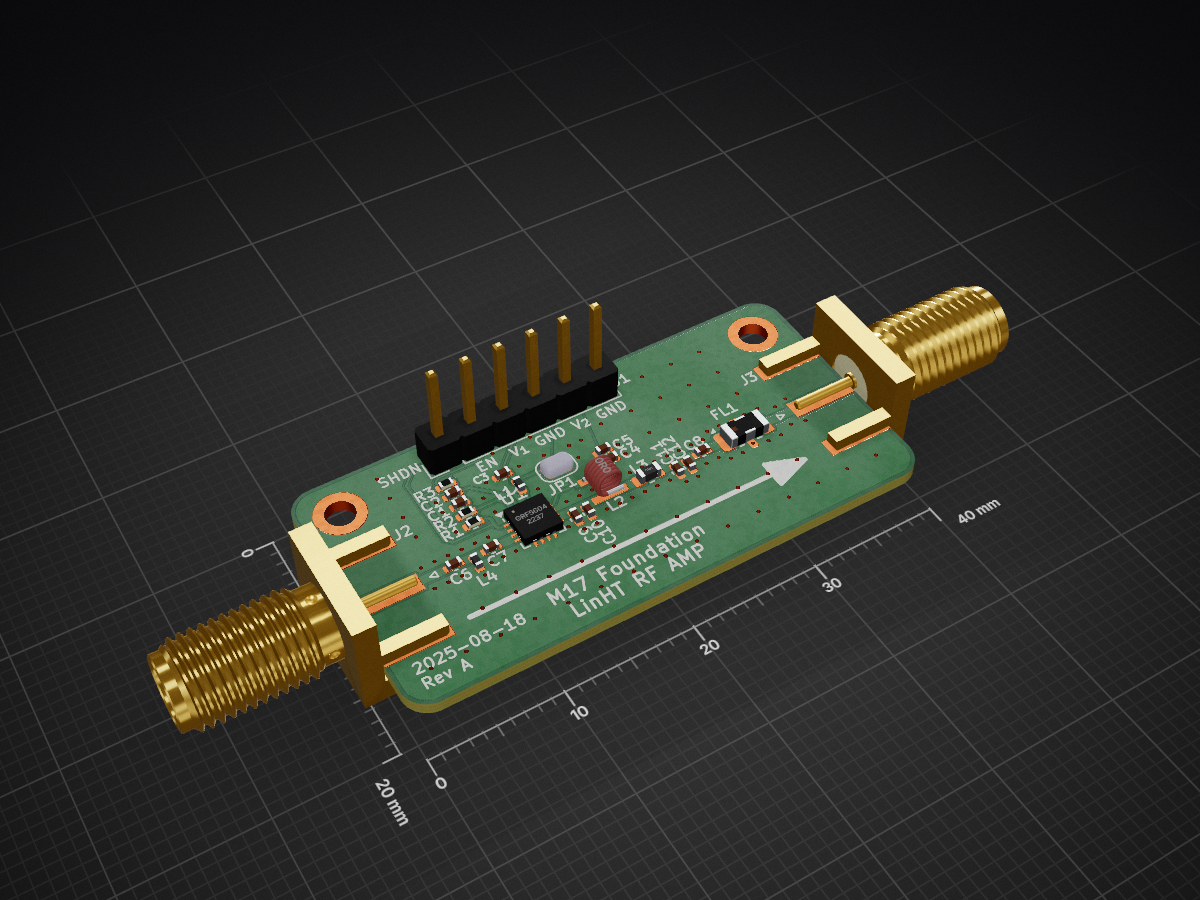
 M17-Project/LinHT-rf-amp14
Test board for the Guerrilla RF GRF5604 RF amplifier integrated circuit
LinHT rf amp is an open-source printed circuit board by M17-Project, from the M17-Project/LinHT-rf-amp repository on GitHub. It is a 4-layer board of 40 × 20 mm with 27 parts on 15 nets, routed with 44 tracks and 109 vias.
It is built around the GRF5604 and LFCN-490. Its parts include 12 capacitors, 4 inductors, 3 resistors, 3 connectors and 1 IC. It belongs with the audio and music and radio and wireless boards of this library.

Standalone RF power amplifier module for the LinHT handheld, built around the Guerrilla RF GRF5604.
This repository houses a proof-of-concept (PoC) board used to evaluate matching, biasing, efficiency, and linearity in the 420–450 MHz band. Results from this effort will feed back into, and eventually be integrated with the
main LinHT hardware project.
Goal: validate a practical PA chain for LinHT. Once the approach is proven, the PA will be integrated into LinHT to enable higher output power (targeting ≈ 5 W at the radio level). This board is for laboratory development and characterization.
This hardware is intended for licensed amateur radio experimentation. Users are responsible for ensuring compliance with local regulations (spectral masks, occupied bandwidth, power limits, spurious emissions) before on-air use.
This work is licensed under a
Creative Commons Attribution-NonCommercial-ShareAlike 4.0 International License.

| Qty | Value | Footprint | References |
|---|---|---|---|
| 3 | 1n | Capacitor_SMD:C_0402_1005Metric | C1, C2, C4 |
| 2 | 33p | Capacitor_SMD:C_0402_1005Metric | C7, C9 |
| 2 | MountingHole_Pad_MP | MountingHole:MountingHole_2.2mm_M2_DIN965_Pad | H1, H2 |
| 1 | 100k | Resistor_SMD:R_0402_1005Metric | R1 |
| 1 | 100n | Capacitor_SMD:C_0402_1005Metric | C3 |
| 1 | 100p | Capacitor_SMD:C_0402_1005Metric | C8 |
| 1 | 10n | Inductor_SMD:L_0402_1005Metric | L4 |
| 1 | 10p | Capacitor_SMD:C_0402_1005Metric | C6 |
| 1 | 10u | Capacitor_SMD:C_0402_1005Metric | C5 |
| 1 | 1k96 | Resistor_SMD:R_0402_1005Metric | R2 |
| 1 | 2.4nH | Inductor_SMD:L_0603_1608Metric | L3 |
| 1 | 20nH | Inductor_SMD:L_0402_1005Metric | L1 |
| 1 | 23nH | Parts:0908SQ-23N | L2 |
| 1 | 27p | Capacitor_SMD:C_0402_1005Metric | C11 |
| 1 | 3p | Capacitor_SMD:C_0402_1005Metric | C12 |
| 1 | 6k04 | Resistor_SMD:R_0402_1005Metric | R3 |
| 1 | 6p8 | Capacitor_SMD:C_0402_1005Metric | C10 |
| 1 | GRF5604 | Parts:QFN-16-1EP_3x3mm_P0.5mm_EP1.7x1.7mm_ThermalVias | U1 |
| 1 | INPUT | Connector_Coaxial:SMA_Amphenol_132289_EdgeMount | J2 |
| 1 | LFCN-490 | Filter:Filter_Mini-Circuits_FV1206 | FL1 |
| 1 | OUTPUT | Connector_Coaxial:SMA_Amphenol_132289_EdgeMount | J3 |
| 1 | SIGNALS | Connector_PinHeader_2.54mm:PinHeader_1x06_P2.54mm_Vertical | J1 |
| 1 | SolderJumper_2_Open | Jumper:SolderJumper-2_P1.3mm_Open_RoundedPad1.0x1.5mm | JP1 |
OpenAir-Lab/capstone-project
ECE 438X Senior Design Capstone Project


labdvm/SX1255-Tetra-TMO-HS-HAT
Modified sdr transciever for digital and analog modes include Tetra-TMO


pms67/HadesFCS
Complete flight control system designed from scratch. Hardware designed with KiCad.


loxodes/vna
Under development open hardware microwave vector network analyzer
It measures 40 × 20 mm and has 4 copper layers, 0.98 mm thick.
27 parts, built around the GRF5604 and LFCN-490. The full list of its parts is on this page, with links to each part's symbol and footprint where PCBKit's library has them.
From the M17-Project/LinHT-rf-amp repository on GitHub, at the commit this page was made from: the board is LinHT-rf-amp.kicad_pcb and its schematic LinHT-rf-amp.kicad_sch. PCBKit opens the board in the browser, with nothing to install.
Its repository states no licence, so its author keeps all rights: ask M17-Project before reusing the design.