2 layers95 × 147.3 mm

 LucaBenzi/orologio-eink2
Orologio da tavolo e-ink con ESP32-C3, batteria LiFePO4 e sync NTP - 2 anni di autonomia con una ricarica USB-C
Progetto is an open-source printed circuit board by LucaBenzi, from the LucaBenzi/orologio-eink repository on GitHub, published under the MIT licence. It is a 2-layer board of 105.8 × 53.8 mm with 63 parts on 53 nets, routed with 399 tracks and 108 vias.
It is built around the ESP32-C3-MINI-1-N4, AO3401A and BAT60JFILM, with the SS14 among its other parts. Its parts include 13 resistors, 11 capacitors, 4 switches, 3 ICs and 3 transistors. It belongs with the lEDs and displays and home automation and IoT boards and the ESP32 and RISC-V boards of this library.


E-ink desk clock with a 3.7" display, ESP32-C3 and LiFePO4 battery. Connects to WiFi, syncs time via NTP and runs for about 2 years on a single ~2-hour USB-C charge.
Philosophy: "Place it and it works. Recharge it every 2 years."
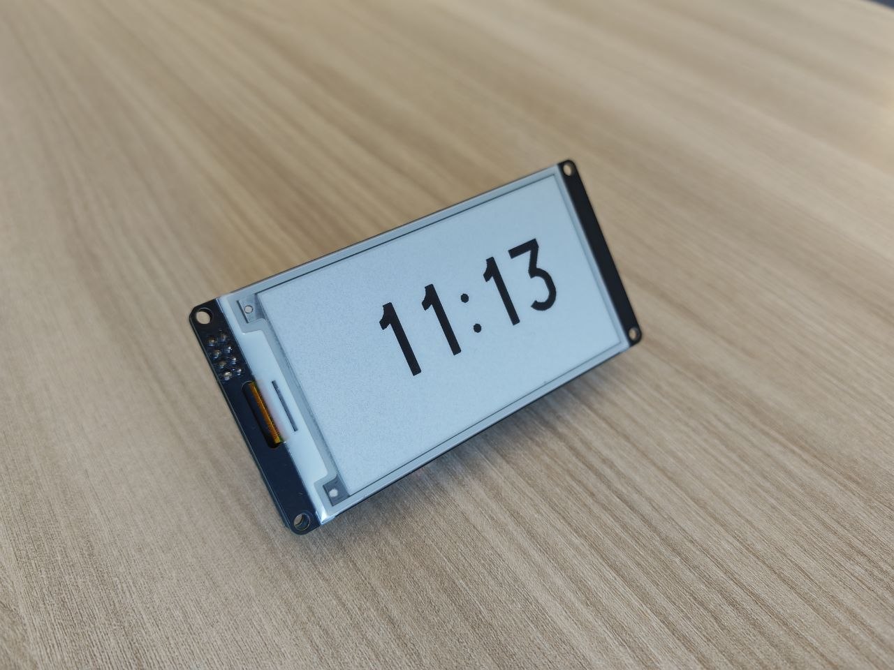
| Component | Model |
|---|---|
| MCU | ESP32-C3-MINI-1 |
| Display | WeAct Studio 3.7" e-Paper (GDEY037T03, driver UC8253) |
| Battery | 2x LiFePO4 18650 1800 mAh in parallel |
| Charger IC | TP5000 (CC/CV, cutoff 3.6 V) |
| LDO | MCP1700-330 |
| Connector | USB Type-C |
| Crystal | 32.768 kHz SMD 3215 |
Full pinout and circuit details are in docs/specifiche.md.
firmware/
  orologio_secondi.ino      # Arduino firmware (ESP32-C3)
  setup.html                 # WiFi configuration page (captive portal)
  telemetria_apps_script.js  # Google Apps Script for telemetry
pcb/
  progetto.kicad_pro         # KiCad 8 project
  progetto.kicad_sch         # schematic
  progetto.kicad_pcb         # PCB layout
  libs/                      # custom libraries and LCSC components
  loghi/                     # SVG logos on the board (CE, RoHS)
  production/                # Gerber, BOM, pick & place for JLCPCB
docs/
specifiche.md # full technical specificationsesp32 by Espressif (ESP32-C3)In orologio_secondi.ino, uncomment the line matching the installed battery pack:
#define BATTERIA_LIFEPO4    // LiFePO4 (default)
//#define BATTERIA_LIPO     // Li-Po / Li-ion
//#define BATTERIA_3AA      // 3x AA alkaline
This must match the jumper configuration on the PCB (JP_DIODE, JP_LDO, JP_CS).
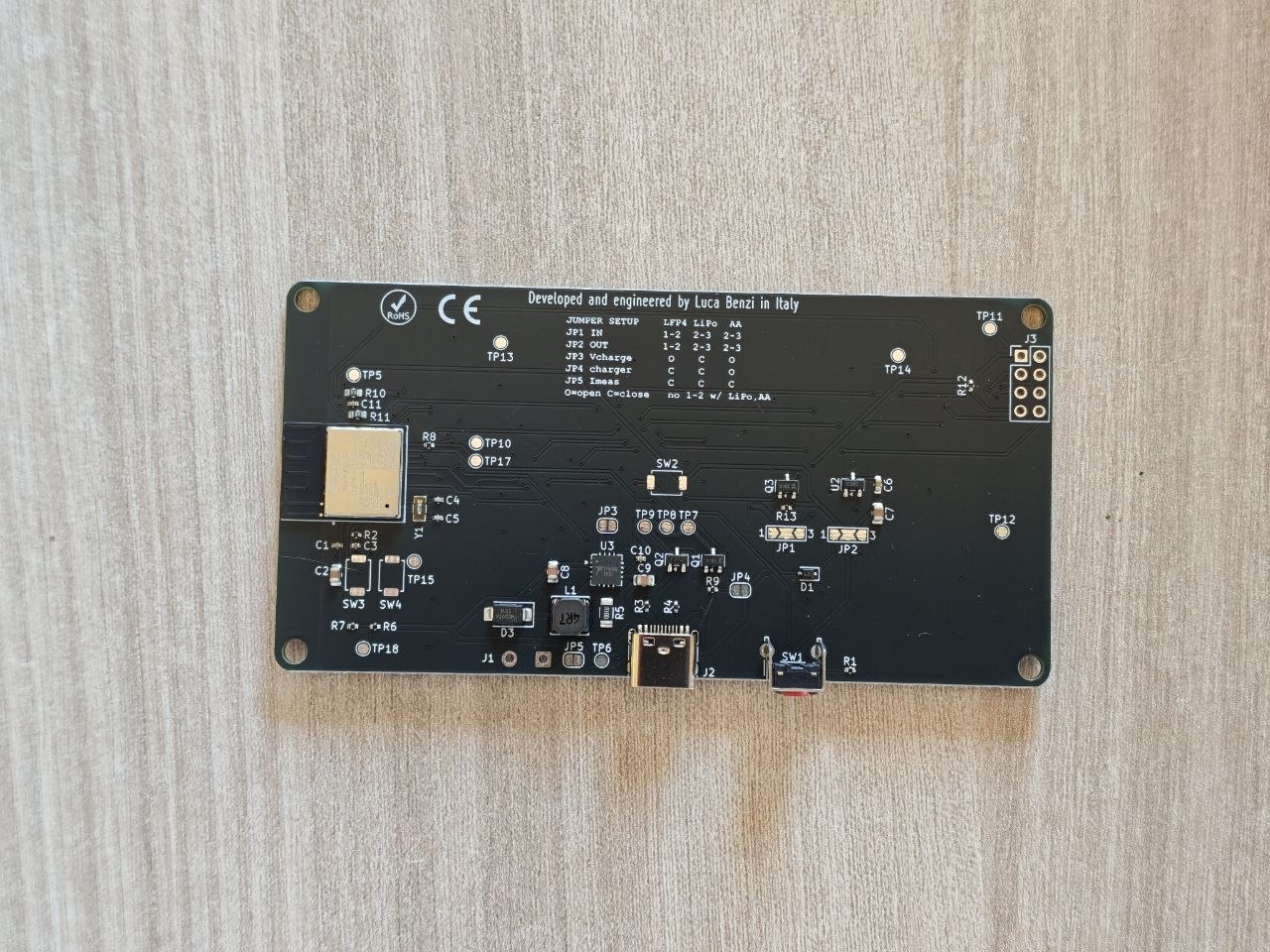
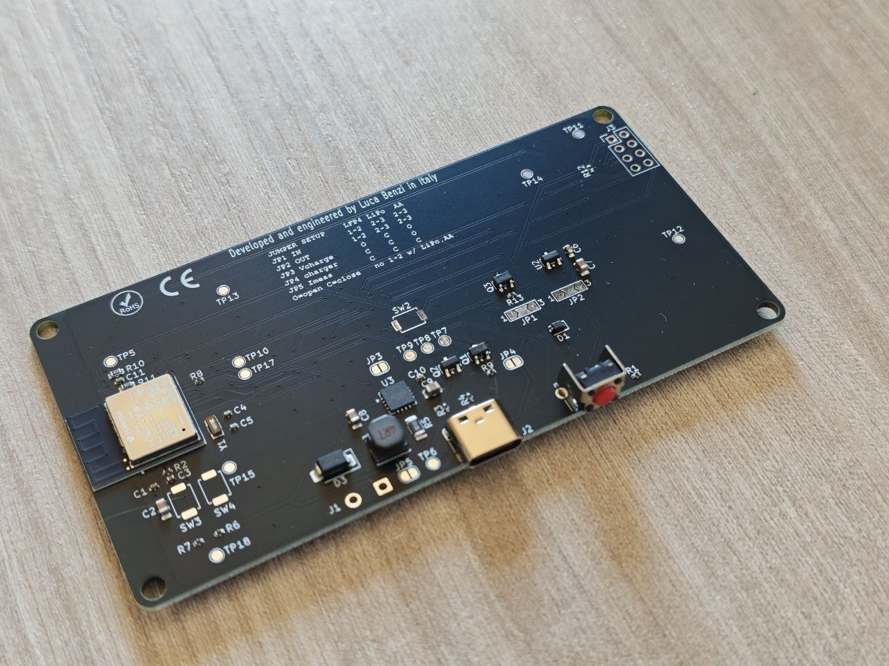
The KiCad project is in pcb/. The production/ folder contains files ready for ordering on JLCPCB:
progetto.zip — Gerber filesbom.csv — Bill of Materials with LCSC part numberspositions.csv — pick & place fileThis project is open source. See the LICENSE file for details.
| Qty | Value | Footprint | References |
|---|---|---|---|
| 13 | TestPoint | TestPoint:TestPoint_Pad_D1.5mm | TP5, TP6, TP7, TP8, TP9, TP10, TP11, TP12, TP13, TP14, TP15, TP17, TP18 |
| 4 | 10u | Capacitor_SMD:C_0805_2012Metric | C2, C7, C8, C9 |
| 4 | MountingHole | MountingHole:MountingHole_3.2mm_M3 | H1, H2, H3, H4 |
| 3 | 10K | Resistor_SMD:R_0402_1005Metric | R1, R2, R6 |
| 3 | SW_Push | Button_Switch_SMD:SW_SPST_TS-1088-xR020 | SW2, SW3, SW4 |
| 2 | 100K | Resistor_SMD:R_0402_1005Metric | R9, R13 |
| 2 | 100n | Capacitor_SMD:C_0402_1005Metric | C1, C11 |
| 2 | 18p | Capacitor_SMD:C_0402_1005Metric | C4, C5 |
| 2 | 2M | Resistor_SMD:R_0603_1608Metric | R10, R11 |
| 2 | 5.1K | Resistor_SMD:R_0402_1005Metric | R3, R4 |
| 2 | AO3401A | Package_TO_SOT_SMD:SOT-23 | Q1, Q3 |
| 2 | LiFePO4/Lipo_AA | Jumper:SolderJumper-3_P2.0mm_Open_TrianglePad1.0x1.5mm_NumberLabels | JP1, JP2 |
| 2 | Lifepo4/Lipo | Jumper:SolderJumper-2_P1.3mm_Open_RoundedPad1.0x1.5mm | JP3, JP4 |
| 1 | 0.1 | Resistor_SMD:R_1206_3216Metric | R5 |
| 1 | 0.1u | Capacitor_SMD:C_0402_1005Metric | C10 |
| 1 | 100k | Resistor_SMD:R_0402_1005Metric | R12 |
| 1 | 15K | Resistor_SMD:R_0402_1005Metric | R7 |
| 1 | 1M | Resistor_SMD:R_0402_1005Metric | R8 |
| 1 | 1u | Capacitor_SMD:C_0402_1005Metric | C3 |
| 1 | 1u | Capacitor_SMD:C_0603_1608Metric | C6 |
| 1 | 2N7002 | Package_TO_SOT_SMD:SOT-23 | Q2 |
| 1 | 4.7u | Inductor_SMD:L_Sunlord_SWPA5040S | L1 |
| 1 | BAT60JFILM | Diode_SMD:D_SOD-323 | D1 |
| 1 | Conn_01x02_Pin | Connector_Wire:SolderWire-0.5sqmm_1x02_P4.6mm_D0.9mm_OD2.1mm | J1 |
| 1 | Crystal | Crystal:Crystal_SMD_3215-2Pin_3.2x1.5mm | Y1 |
| 1 | Display | Connector_PinHeader_2.54mm:PinHeader_2x04_P2.54mm_Vertical | J3 |
| 1 | ESP32-C3-MINI-1-N4 | lcsc_footprints:C2838502_WIFIM-SMD_ESP32-C3-MINI-1 | U1 |
| 1 | MCP1700x-330xxTT | Package_TO_SOT_SMD:SOT-23 | U2 |
| 1 | SS14 | Diode_SMD:D_SMA | D3 |
| 1 | SW_Push | Button_Switch_THT:SW_Tactile_SPST_Angled_PTS645Vx31-2LFS | SW1 |
| 1 | SolderJumper_2_Bridged | Jumper:SolderJumper-2_P1.3mm_Open_RoundedPad1.0x1.5mm | JP5 |
| 1 | TP5000 | Package_DFN_QFN:QFN-16-1EP_4x4mm_P0.65mm_EP2.5x2.5mm | U3 |
| 1 | USB_C_Receptacle_USB2.0_16P | Connector_USB:USB_C_Receptacle_HRO_TYPE-C-31-M-12 | J2 |

supsenpaii/iot-classroom
Website lớp học tương tác: React, Express, SQLite và giao thức WebSocket kết nối ESP32. Chưa kèm firmware.

paclema/iot-postbox
Integrated open-source HW and FW for an IoT smart mailbox sensor with Wi-Fi and LoRaWAN connectivity.

MAATHES-THILAK-K/4CH_RELAY_TIMER
ESP32C3 Mini Based 4CH Relay With Timer Control

KVR-CIBER/sc02-solar-hypercar
SC-02 Solar Hypercar: 3D-printbare Le-Mans-racer op zonne-energie met Pi 4 + ESP32-S3, CadQuery-CAD en three.js-simulatie

noellayang/chipsat-v1
Custom ESP32-C3 power-management testbed for small satellite firmware experiments


DomPka/LuxLibre
Pick a light · Compare · Web apps · Firmware · Design your own · Build a FlashKa · Repository map · Help
It measures 105.8 × 53.8 mm and has 2 copper layers, 1.6 mm thick.
63 parts, built around the ESP32-C3-MINI-1-N4, AO3401A, BAT60JFILM and SS14. The full list of its parts is on this page, with links to each part's symbol and footprint where PCBKit's library has them.
From the LucaBenzi/orologio-eink repository on GitHub, at the commit this page was made from: the board is pcb/progetto.kicad_pcb and its schematic pcb/progetto.kicad_sch. PCBKit opens the board in the browser, with nothing to install.
Its repository publishes it under the MIT licence: you may reuse it on that licence's terms (keep the author's notice, and for a copyleft licence share your changes alike).