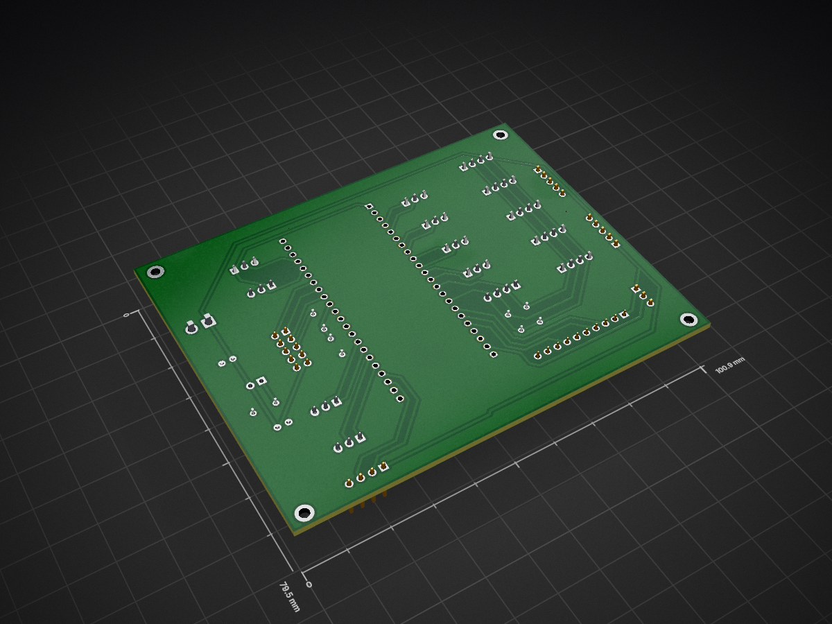
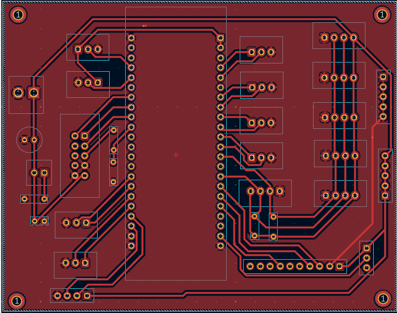
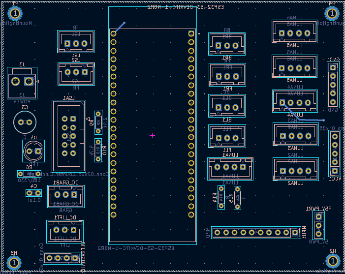
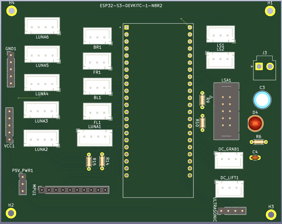
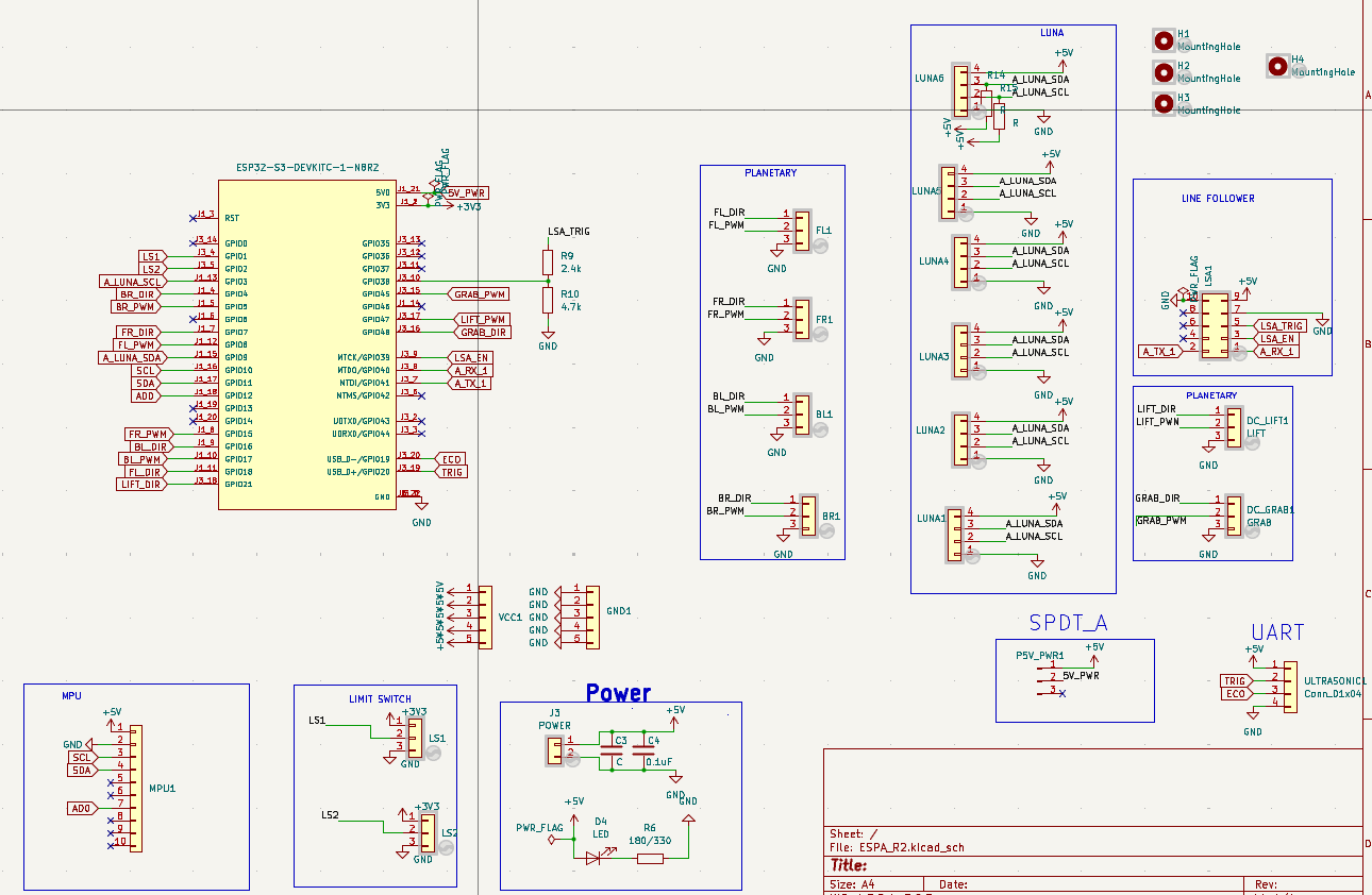
ESP32-S3 based breakout PCB designed for Robocon 2024 R2 autonomous robot, supporting sensor interfacing, motor control, and rapid testing of navigation and ball-handling mechanisms.
ESPA R2 is an open-source printed circuit board by Loki045, from the Loki045/R2_Robocon_24_Breakout_devboard repository on GitHub. It is a 2-layer board of 100.9 × 79.5 mm with 34 parts on 52 nets, routed with 193 tracks and 2 vias.
It is built around the ESP32-S3-DEVKITC-1-N8R2. Its parts include 5 resistors, 2 capacitors, 2 connectors and 1 diode. It belongs with the robots and motor control and interfaces and adapters boards and the ESP32 boards of this library.
ESP32-S3 based breakout PCB designed for Robocon 2024 R2 autonomous robot, supporting sensor interfacing, motor control, and rapid testing of navigation and ball-handling mechanisms.
Robocon 2024 – R2 Autonomous Breakout PCB with Devboard
This repository contains the hardware design files for the R2 Breakout PCB used for testing Robocon 2024 autonomous robot.
The board was designed as a ESP32-S3 stackable breakout and testing interface, enabling direct connection of sensors, motors, and power modules required for autonomous robot development.
📌 Robot Task Overview
In Robocon 2024, Robot 2 (R2) was designed as a fully autonomous robot.
Its primary tasks included:
Following a predefined path using line follower sensors
Navigating toward Area 3
Detecting team-colored balls placed in Area 3 (Red/Blue)
Picking balls and placing them into designated silos
The R2 with devboard breakout PCB enabled rapid testing and integration of sensors, locomotion motors, and mechanism motors required for autonomous navigation and ball placement.
⚙️ Board Overview
The R2 PCB was developed as a Initial testing and integration platform, allowing:
Direct stacking of ESP32-S3 Development Board
Easy connection of multiple sensors
Support for locomotion and mechanism motors
Clean distribution of regulated power inputs
Rapid hardware testing during autonomous robot development
This modular design simplified debugging and allowed flexible hardware testing during algorithm development.
🔧 Key Features
ESP32-S3 compatible stacking layout
Multiple sensor interface connectors
Motor control connectors
Power input connector
On-board LED indicators
Decoupling capacitors for stable operation
Pull-up / current limiting resistors
Dedicated GPIO breakout headers
🔌 Supported Sensors
This PCB supported direct connection of commonly used autonomous sensors.
Sensors Used:
6 × Luna Distance Sensors
MPU9250 (IMU Sensor)
LSA1 Line Follower Sensor
These sensors were used for navigation, obstacle detection, and path following.
🎮 Motor Interfaces
The board supported both locomotion and mechanism motors.
Locomotion Motors:
4 Motor connectors for drive system
Mechanism Motors:
2 Motor connectors for grab and lift mechanism
These motors supported locomotion and ball placement operations in silo .
⚡ Power Interface
Power was supplied through an external regulated source.
Input:
Power Input Connector (Voltage supplied externally)
On-board Components:
Capacitors for filtering
Resistors for signal stability
LED indicators for power/status
🧠 Application in Autonomous Robot
This breakout board enabled:
Sensor testing and calibration
Autonomous navigation testing
Motor control validation
Rapid integration of hardware modules
It played a key role in enabling the autonomous behavior of R2 robot during Robocon 2024.
This PCB was used in initial testing the Robocon 2024 R2 Autonomous Robot, supporting sensor integration, navigation testing, and mechanism control required for ball detection and silo placement.
👨💻 Contribution
Developed as part of Robocon 2024 electronics development, contributing to hardware integration and breakout design for autonomous robot testing.
1) Along with using with TMC2209 motor drivers, I have removed R8, R15, R16, R17, R18, R19 because the R value was accidentally too high. I have shorted R8, R16, R17, and left open R15, R18, R19.
A custom ESP32-S3-based PCB designed in KiCad for automated soil sample analysis, featuring drivers and interfaces for environmental sensors, peristaltic pumps, and auger drilling actuators.
Utilization of Electrochemical Impedance Spectroscopy for the Detection of Drugs
51 parts1MIT
Questions
How big is the ESPA R2 PCB?
It measures 100.9 × 79.5 mm and has 2 copper layers, 1.6 mm thick.
What parts does the ESPA R2 use?
34 parts, built around the ESP32-S3-DEVKITC-1-N8R2. The full list of its parts is on this page, with links to each part's symbol and footprint where PCBKit's library has them.
Where can I download the ESPA R2 KiCad files?
From the Loki045/R2_Robocon_24_Breakout_devboard repository on GitHub, at the commit this page was made from: the board is R2_RCU_2024-25/ESPA_R2.kicad_pcb and its schematic R2_RCU_2024-25/ESPA_R2.kicad_sch. PCBKit opens the board in the browser, with nothing to install.
Can I use the ESPA R2 design in my own project?
Its repository states no licence, so its author keeps all rights: ask Loki045 before reusing the design.