


6 layers110.9 × 93 mm
ESP32-Rotator v0.2
brokebit/Rotator-ESP32-S3-Board
Rotator Controller based on an ESP32-S3 micro and Clearpath Servos
89 parts

ESP32-S3 MeatLoaf hardware for Commodore C64/C128, including KiCad PCB designs, production files and firmware.
Meatloaf is an open-source printed circuit board by LeshanDaFo, from the LeshanDaFo/MeatLoaf-Hardware-ClausS repository on GitHub. It is a 2-layer board of 63.7 × 73 mm with 34 parts on 74 nets, routed with 251 tracks and 26 vias.
It is built around the ESP32-S3-DEVKITC-1-N8 and MMBT3904. Its parts include 13 resistors, 7 transistors, 3 diodes, 3 connectors and 2 capacitors. It belongs with the retro computing and games boards and the ESP32 boards of this library.
Hardware designs and ready-to-flash firmware packages for the MeatLoaf project.
MeatLoaf is an ESP32-based interface for Commodore computers. It connects to the IEC serial bus and can provide access to disk images, SD-card files, network services, and other MeatLoaf firmware features.
This repository contains an independent hardware implementation maintained by Claus Schlereth. The original MeatLoaf firmware is developed separately in the upstream MeatLoaf repository.
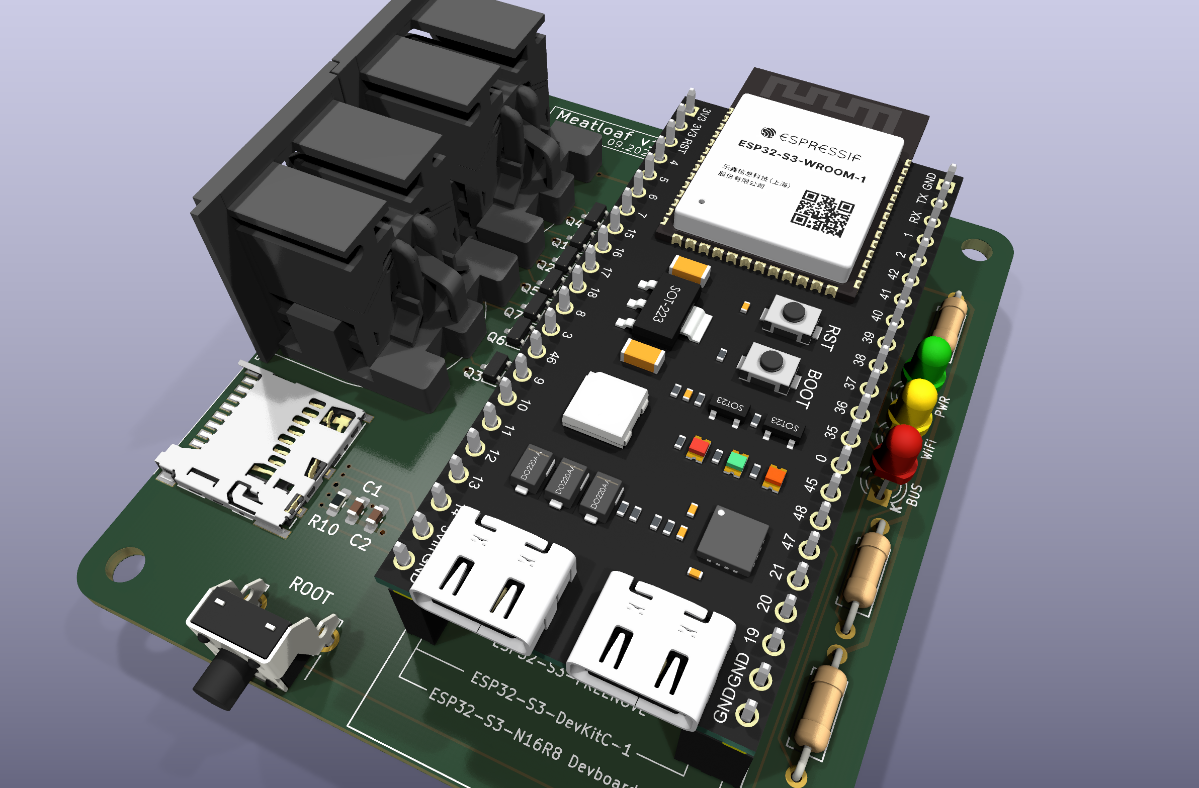
The image shows the currently published PCB v1.0 revision. It may be replaced when a newer hardware revision becomes the current reference design.
| Revision | Status | Hardware documentation | Firmware |
|---|---|---|---|
| PCB v1.0 | Published | Documentation · KiCad files · Production files | Firmware packages · Installation instructions |
Each hardware revision has its own design, documentation, images, and manufacturing files. Files from different revisions must not be mixed.
The table above is the starting point for revision-specific compatibility, placement, GPIO assignments, schematics, PCB images, KiCad sources, 3D data, and manufacturing files. The hardware overview provides a revision-independent index of the available design material.
Firmware/ revision directory or from GitHub Releases.Before ordering or assembling a PCB:
The files under Production/ are intended for PCB manufacturing and assembly. The editable KiCad project remains the authoritative design source.
Firmware packages are hardware-specific and may also differ by flash capacity, PSRAM capacity, GPIO assignments, and other board configuration details. A development-board name or matching connector position alone does not determine the correct package.
Use the firmware link for the selected hardware revision and follow the
Firmware/README.md instructions to identify the module
and choose a compatible package. Do not assume that firmware for one revision
or memory configuration is suitable for another.
.
├── Hardware/
│   ├── README.md
│   └── PCB-v1.0/
│       ├── README.md
│       ├── 3D/
│       ├── Images/
│       ├── KiCad/
│       ├── PDF/
│       └── Production/
├── Firmware/
│   ├── README.md
│   └── v1.0/
├── LICENSE.md
└── LIZENZ.md
Future hardware revisions will be added as separate directories, for example Hardware/PCB-v1.1/ or Hardware/PCB-v2.0/.
| Date | Revision | Summary |
|---|---|---|
| 2026-10-21 | PCB v1.0 | Initial published hardware revision with KiCad sources, schematic PDF, PCB images, 3D assembly, production files, and N8R8/N16R8 firmware packages |
Detailed technical changes should be documented with the files for the corresponding hardware revision. This table records only published repository revisions.
This is a hobby hardware project under active development.
Features, test status, component choices, and firmware compatibility may differ between hardware revisions. Always consult the documentation for the exact PCB revision instead of assuming that information for another revision also applies.
The original hardware design materials are provided under the project's custom non-commercial hardware license:
Private builds and non-profit group orders at documented actual cost are permitted under the conditions of that license. Commercial use requires separate written permission.
Firmware, KiCad libraries, component models, trademarks, and other third-party materials may be governed by separate licenses or usage conditions. The project license does not grant additional rights to those materials.
The project is provided for experimentation and hobby use without a guarantee of functionality, electrical safety, regulatory compliance, or fitness for a particular purpose.
Check wiring, connector orientation, supply voltage, component ratings, and the selected hardware revision before powering the board.
| Qty | Value | Footprint | References |
|---|---|---|---|
| 6 | 10k | Resistor_SMD:R_0603_1608Metric_Pad0.98x0.95mm_HandSolder | R1, R2, R3, R4, R5, R10 |
| 5 | 2N7002 | Package_TO_SOT_SMD:SOT-23 | Q1, Q2, Q3, Q4, Q5 |
| 4 | MountingHole | MountingHole:MountingHole_3.2mm_M3 | H1, H2, H3, H4 |
| 3 | 470 | Resistor_THT:R_Axial_DIN0207_L6.3mm_D2.5mm_P10.16mm_Horizontal | R11, R12, R13 |
| 2 | 100k | Resistor_SMD:R_0603_1608Metric_Pad0.98x0.95mm_HandSolder | R7, R9 |
| 2 | 4k7 | Resistor_SMD:R_0603_1608Metric_Pad0.98x0.95mm_HandSolder | R6, R8 |
| 2 | Commodore IEC | Meatloaf:Commodore_IEC | J2, J3 |
| 2 | MMBT3904 | Package_TO_SOT_SMD:SOT-23 | Q6, Q7 |
| 1 | 100nF | Capacitor_SMD:C_0603_1608Metric_Pad1.08x0.95mm_HandSolder | C2 |
| 1 | 10uF | Capacitor_SMD:C_0603_1608Metric_Pad1.08x0.95mm_HandSolder | C1 |
| 1 | 503398-1892 | Meatloaf:MOLEX_503398-1892 | J1 |
| 1 | BUS | LED_THT:LED_D3.0mm | D3 |
| 1 | ESP32-S3-DevKitC | Meatloaf:ESP32-S3-DevKitC-1 | U1 |
| 1 | Power | LED_THT:LED_D3.0mm | D1 |
| 1 | ROOT | Button_Switch_THT:SW_Tactile_SPST_Angled_PTS645Vx58-2LFS | SW1 |
| 1 | WiFi | LED_THT:LED_D3.0mm | D2 |
brokebit/Rotator-ESP32-S3-Board
Rotator Controller based on an ESP32-S3 micro and Clearpath Servos

willem-pennings/balancing-cube
A cube that balances itself in a corner or edge using reaction wheels

jazzmonger/Traeger-PID-Controller
Traeger Smoker/Grill Controller based on an

ohasanov-hbrw/tribit32-advanced
A tri-microcontroller, overengineered GameBoy Advance clone. More value was given to the controls and the exterior look, which is cool!


FIPATECH/CDFR26_PAMI
Open source firmware and PCB for a differential mobile robot (PAMI) based on ESP32-S3 - Coupe de France de Robotique

dnhutchins/ETC_Express_Reverse_Eng
The ultimate goal of this work is to develop an interface to use the control surface from a legacy ETC Express 24/48 lighting controller as a modern EOSNomad compatible programming and fader wing.
It measures 63.7 × 73 mm and has 2 copper layers, 1.6 mm thick.
34 parts, built around the ESP32-S3-DEVKITC-1-N8 and MMBT3904. The full list of its parts is on this page, with links to each part's symbol and footprint where PCBKit's library has them.
From the LeshanDaFo/MeatLoaf-Hardware-ClausS repository on GitHub, at the commit this page was made from: the board is Hardware/PCB-v1.0/KiCad/Meatloaf.kicad_pcb and its schematic Hardware/PCB-v1.0/KiCad/Meatloaf.kicad_sch. PCBKit opens the board in the browser, with nothing to install.
Its repository states no licence, so its author keeps all rights: ask LeshanDaFo before reusing the design.