2 layers44.5 × 37 mm

 LeoDJ/SSD1303_Breakout1
A breakout board for a specific SSD1303 OLED display
SSD1303 Breakout is an open-source printed circuit board by LeoDJ, from the LeoDJ/SSD1303_Breakout repository on GitHub. It is a 2-layer board of 62.5 × 49.5 mm with 59 parts on 31 nets, routed with 170 tracks and 33 vias.
It is built around the TPS61040DBV, XC6206P332MR and 1N5819WS, with the S8050 and X05A20L22T among its other parts. Its parts include 15 resistors, 8 capacitors, 4 diodes, 3 transistors and 2 ICs. It belongs with the lEDs and displays and interfaces and adapters boards of this library.


A breakout board for a specific SSD1303 OLED display.
Optimized for low-cost PCB assembly services from a specific chinese manufacturer with blue logo.
You can preview the PCB using the amazing KiCanvas. (Or the schematic if I forget to update the PDF ^^' )
| Pin | Function |
|---|---|
| GND | GND |
| VCC | 3.3 - 5 V (up to ~250mA1) |
| CLK | SPI: SCK I²C: SCL |
| DI | SPI: MOSI I²C: SDA |
| RES | Reset (active low) |
| DC | SPI: data/command line I²C: address. 0: 0x3C / 1: 0x3D (default low) |
| CS | SPI: CS |
0x3DSomehow I got a bit carried away for a relatively simple design, but otoh I've learned a lot again.
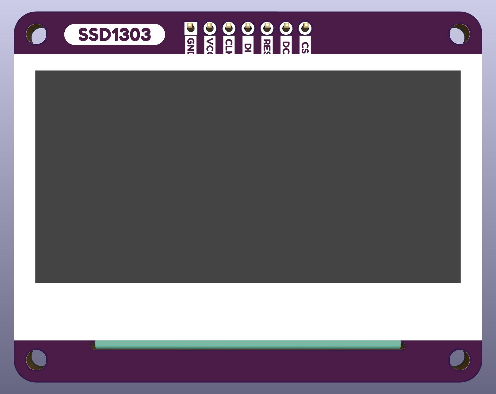
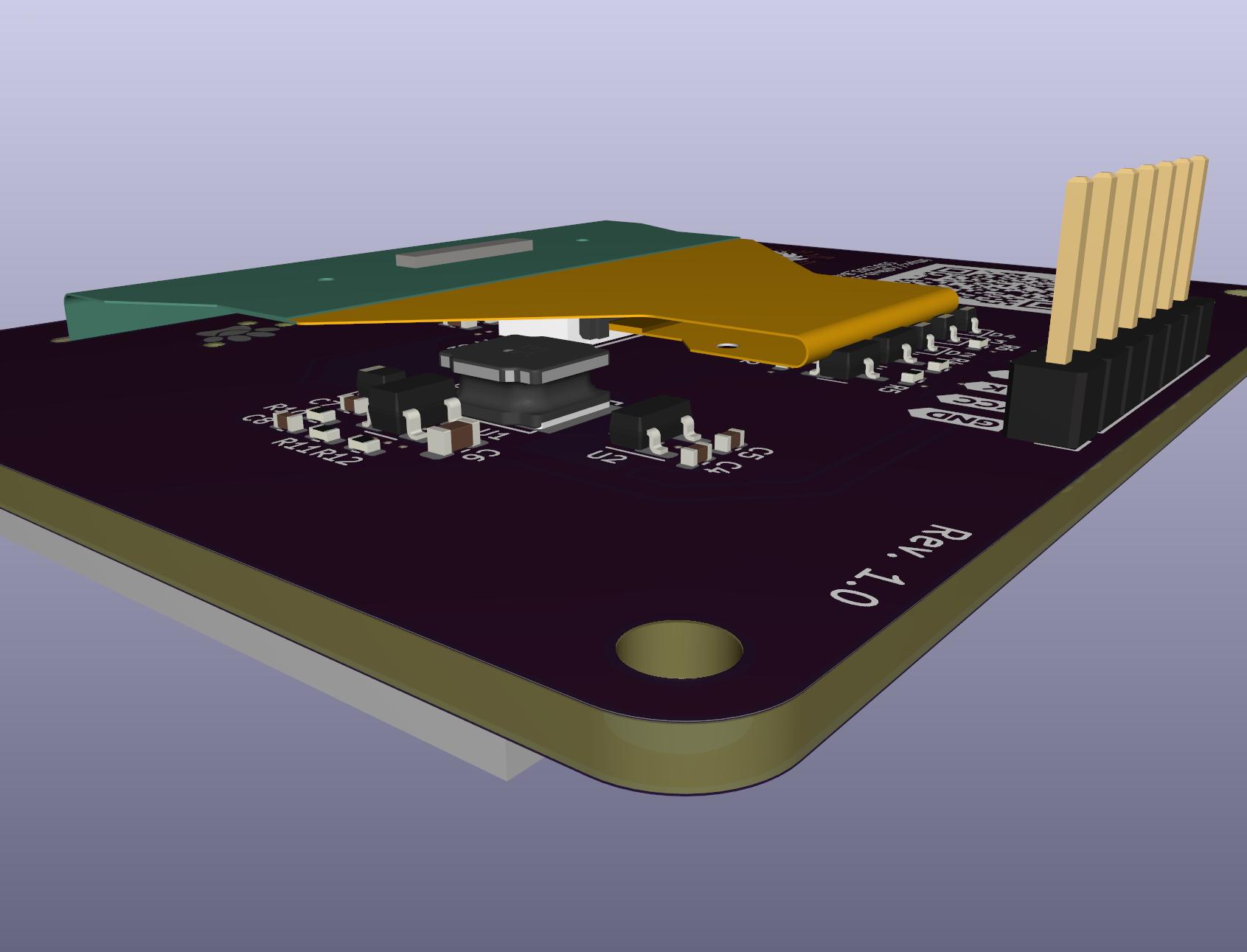
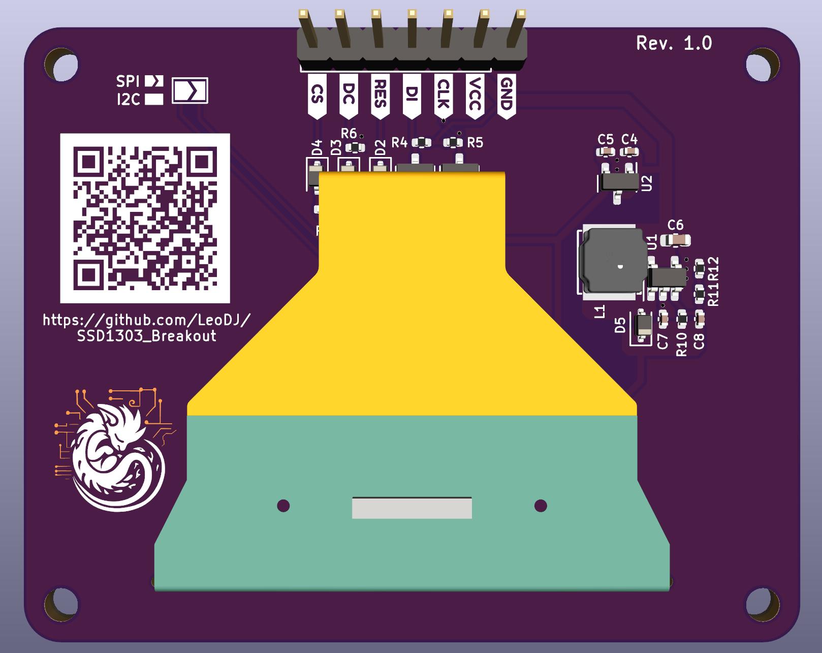
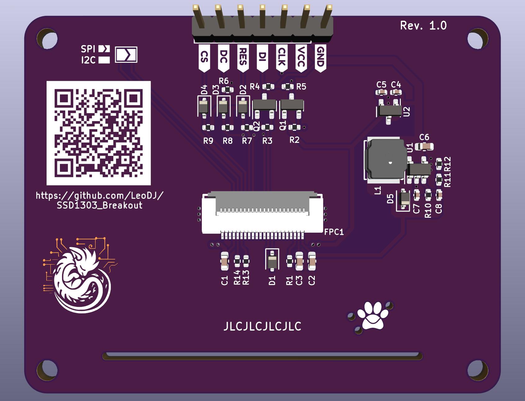
Might draw up to ~250 mA @ 3.3V with all pixels on, guesstimated.
I've measured roughly 50mA @ 12V with the highest brightness and all pixels on, so with pessimistic conversion losses around 750mW. ↩
It appears to shift out some kind of data, maybe from an internal register. The SSD1303 datasheet doesn't give any hint to the behaviour of pin D2 in SPI mode, except to keep it disconnected.
Over time the value that gets shifted out accumulates 1 bits. Starting at some random value with few bits set on power-up. (It probably turns into a constant high signal as soon as it reaches 0xFF, but I could only actually observe it up to 0x7F/0xF7 in my last measurement.)
When the pin is actively pulled low by the SSD1303, it interferes through the diode D1 with the actual data meant for the data input pin D1. ↩
| Qty | Value | Footprint | References |
|---|---|---|---|
| 6 | 100k | Resistor_SMD:R_0402_1005Metric | R6, R7, R8, R9, R13, R14 |
| 5 | 10k | Resistor_SMD:R_0402_1005Metric | R2, R3, R4, R5, R15 |
| 4 | 1N5819WS | Diode_SMD:D_SOD-323 | D2, D3, D4, D5 |
| 2 | 10u | Capacitor_SMD:C_0603_1608Metric | C1, C6 |
| 2 | 10uF/25V | Capacitor_SMD:C_0603_1608Metric | C2, C3 |
| 2 | 1M | Resistor_SMD:R_0402_1005Metric | R1, R10 |
| 2 | 1u | Capacitor_SMD:C_0402_1005Metric | C4, C5 |
| 2 | 2N7002 | Package_TO_SOT_SMD:SOT-23 | Q1, Q2 |
| 2 | G*** | kibuzzard-649270B3 | kibuzzard-649270B3, kibuzzard-649270B3 |
| 2 | G*** | kibuzzard-649270A6 | kibuzzard-649270A6, kibuzzard-649270A6 |
| 2 | G*** | kibuzzard-649270AD | kibuzzard-649270AD, kibuzzard-649270AD |
| 2 | G*** | kibuzzard-6492708E | kibuzzard-6492708E, kibuzzard-6492708E |
| 2 | G*** | kibuzzard-649270BA | kibuzzard-649270BA, kibuzzard-649270BA |
| 2 | G*** | kibuzzard-64927098 | kibuzzard-64927098, kibuzzard-64927098 |
| 2 | G*** | kibuzzard-649270A0 | kibuzzard-649270A0, kibuzzard-649270A0 |
| 1 | clipboard:1a0fa234-2fd2-4559-88f1-580cf3211e09 | ||
| 1 | 10p | Capacitor_SMD:C_0402_1005Metric | C8 |
| 1 | 10uH/<250mΩ | LCSC:IND-SMD_L5.0-W5.0 | L1 |
| 1 | 1uF/25V | Capacitor_SMD:C_0402_1005Metric | C7 |
| 1 | 47k | Resistor_SMD:R_0402_1005Metric | R12 |
| 1 | 68k | Resistor_SMD:R_0402_1005Metric | R11 |
| 1 | G*** | kibuzzard-6492A15D | kibuzzard-6492A15D |
| 1 | G*** | kibuzzard-64927129 | kibuzzard-64927129 |
| 1 | I²C/~{SPI} | Jumper:SolderJumper-2_P1.3mm_Open_TrianglePad1.0x1.5mm | JP2 |
| 1 | LOGO | LeoDJ-kicad:Logo_PCBDerg_Mask_10mm | G*** |
| 1 | LOGO | LOGO | G*** |
| 1 | PinHeader | Connector_PinHeader_2.54mm:PinHeader_1x07_P2.54mm_Vertical | J1 |
| 1 | S8050 | Package_TO_SOT_SMD:SOT-23 | Q3 |
| 1 | TPS61040DBV | Package_TO_SOT_SMD:SOT-23-5 | U1 |
| 1 | X05A20L22T | LCSC:FFC-SMD_22P-P0.50_X05A20L22T | FPC1 |
| 1 | XC6206P332MR | Package_TO_SOT_SMD:SOT-23 | U2 |
The 55 most common of 59 parts.

xiaohail/pixl.js-oled
This project is open source and is solely for learning and research purposes, please do not use it for commercial purposes. Amiibo is a registered trademark of Nintendo, and NTAG21X is a registered trademark of NXP.

calithameridi/corevus
High-flexibility, low-cost mechatronics controller for 3D printers

plinkysynth/plinky_public
a public release of the plinky sw and hw


k-takata/PCB_updi_unbricker
UPDI High Voltage programmer for AVR Dx/Ex and ATtiny series

STB1019/BLINDO2.0
Blindo is an open source project made by the members of IEEE Student Branch 1019 from Brescia University (Università degli Studi di Brescia) in collaboration with the organization (Informatici Senza…
It measures 62.5 × 49.5 mm and has 2 copper layers, 1.6 mm thick.
59 parts, built around the TPS61040DBV, XC6206P332MR, 1N5819WS and S8050. The full list of its parts is on this page, with links to each part's symbol and footprint where PCBKit's library has them.
From the LeoDJ/SSD1303_Breakout repository on GitHub, at the commit this page was made from: the board is SSD1303_Breakout.kicad_pcb and its schematic SSD1303_Breakout.kicad_sch. PCBKit opens the board in the browser, with nothing to install.
Its repository states no licence, so its author keeps all rights: ask LeoDJ before reusing the design.