2 layers68.6 × 53.3 mm

 LMWB/Quattro-Stagioni
RTD-Sensor Breakoutboard and C-Library
RTC Messbruecke from template is an open-source printed circuit board by LMWB, from the LMWB/Quattro-Stagioni repository on GitHub, published under the MIT licence. It is a 2-layer board of 68.6 × 53.3 mm with 45 parts on 51 nets, routed with 161 tracks and 21 vias.
It is built around the R-78E9.0-0.5, LM324 and MAX6105EUR, with the REF195ESZ and US1D among its other parts. Its parts include 21 resistors, 8 capacitors, 8 connectors, 4 ICs and 4 diodes. It belongs with the sensors and measurement boards of this library.


RTD-Sensor Breakoutboard and C-Library
RTD stands for Resistance Temperature Detector. Most common used versions are PT100, PT1000 and KTY.
RTD Messverfahren werden von IC's implementiert wie z.B. der ADS124 von TI. Mit ca. 10€ sind diese jedoch verhaeltnismaessig preisintensiv.
RDT-Sensoren werden typischerweise mit einem konstanten Strom um die 1mA beaufschlagt und der daraus resultierende Spannungsfall wird gemessen.
Die spezifische Kennklienie gibt Aufschluss über die vorherrschende Temperatur.
Dieses einfache Messverfahren hat den Nachteil, dass im interesanten Wertebereich von ca. 0 bis 70 •C nur ein sehr geringer Spannungshub von ca. 250 mV entsteht (abhaengig vom gewaehlten erregerstrom, je kleiner um so besser um die Eigenerwaermung im Sensor zu vermeiden). Die Kurve R = f(T) ist also sehr flach.
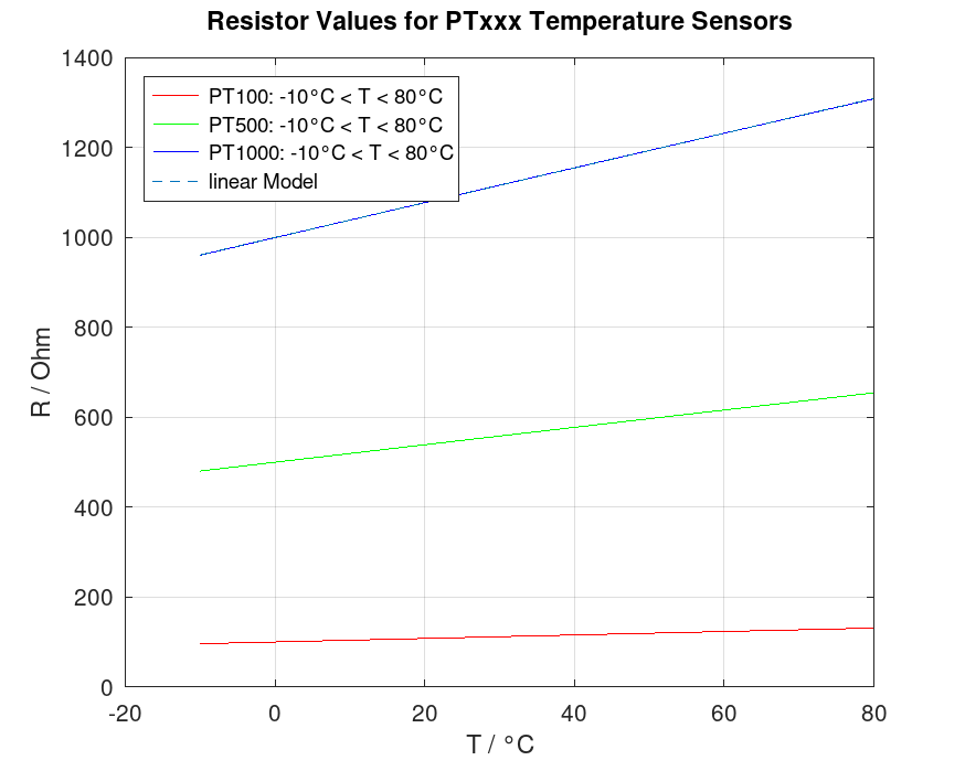 Es erfordert einen sehr hochauflösenden ADC (16bit oder mehr) um einen entsprechenden Ausschlag zu messen.
Ein weitere Nachteil ist, dass die Referenzspannung des ADC nur in einem sehr kleinen Arbeitsbereich verwendet wird.
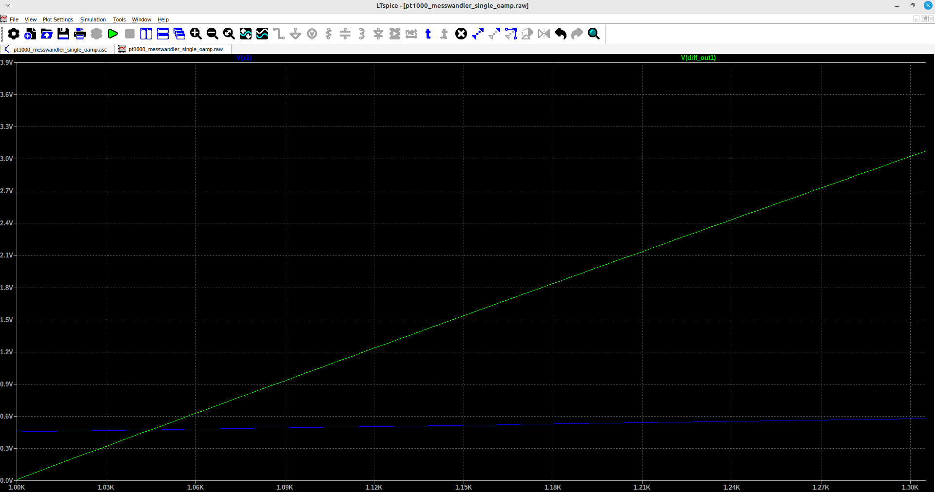
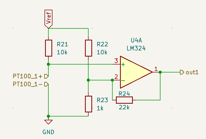 Abhilfe schafft eine einfache Verstärkerschaltung mit einem unipolarem Operationsverstaerker.
Dieses hier vorgestellte analoge Eingangsstufe kann auch für andere physikalische Größen verwendet werden wie z.B. Ladekennlinie moderne Akkus welche von Natur aus sehr flach sind.
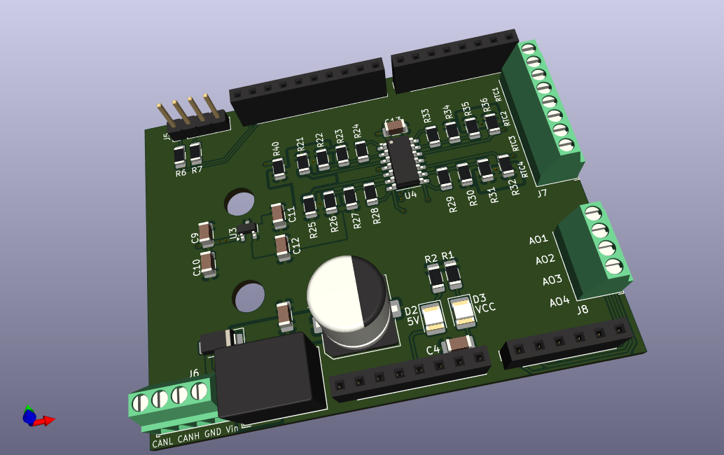
Die oben beschriebene Schaltung wurde im Formfaktor eines vereinfachten Arduino-Shield realisiert. Die Platine implementier 4 Messkanaele da ein 4-fach OP verwendet wurde.
PCB Design and Gerber Files
Simulations and Models
Microcontroller based C-Code
BOM and costs
Results and Discussion
Widerstandsthermometer / Pt100 Fühler
Wissenswertes über RTDs
ADS124 at mouser.com
Wolf-Dieter Schmidt, Sensorschaltungstechnik, Elektronik 8, Vogel Fachbuch, Linearisierung von Silizium-Widerstandssensoren, S. 71
| Qty | Value | Footprint | References |
|---|---|---|---|
| 8 | 10k | Resistor_SMD:R_1206_3216Metric | R21, R22, R25, R26, R31, R32, R35, R36 |
| 4 | 1k | Resistor_SMD:R_1206_3216Metric | R23, R27, R30, R34 |
| 4 | 22k | Resistor_SMD:R_1206_3216Metric | R24, R28, R29, R33 |
| 3 | 0.1u | Capacitor_SMD:C_1206_3216Metric | C9, C12, C13 |
| 2 | 100n | Capacitor_SMD:C_1206_3216Metric_Pad1.33x1.80mm_HandSolder | C1, C4 |
| 2 | 47 | Resistor_SMD:R_1206_3216Metric_Pad1.30x1.75mm_HandSolder | R6, R7 |
| 2 | Conn_01x04 | TerminalBlock_Phoenix:TerminalBlock_Phoenix_MPT-0,5-4-2.54_1x04_P2.54mm_Horizontal | J6, J8 |
| 2 | LED_YE | LED_SMD:LED_1210_3225Metric_Pad1.42x2.65mm_HandSolder | D2, D3 |
| 1 | 0 | Resistor_SMD:R_1206_3216Metric | R40 |
| 1 | 10k | Resistor_SMD:R_1206_3216Metric_Pad1.30x1.75mm_HandSolder | R1 |
| 1 | 10u | Capacitor_SMD:C_1206_3216Metric | C10 |
| 1 | 1u | Capacitor_SMD:C_1206_3216Metric | C11 |
| 1 | 3k3 | Resistor_SMD:R_1206_3216Metric_Pad1.30x1.75mm_HandSolder | R2 |
| 1 | 47u | Capacitor_SMD:CP_Elec_10x12.5 | C2 |
| 1 | Analog | Connector_PinSocket_2.54mm:PinSocket_1x06_P2.54mm_Vertical | J3 |
| 1 | Conn_01x04 | Connector_PinHeader_2.54mm:PinHeader_1x04_P2.54mm_Vertical | J5 |
| 1 | Conn_01x08 | TerminalBlock_Phoenix:TerminalBlock_Phoenix_MPT-0,5-8-2.54_1x08_P2.54mm_Horizontal | J7 |
| 1 | D_Zener | Diode_SMD:D_1206_3216Metric | D4 |
| 1 | Digital/PWM | Connector_PinSocket_2.54mm:PinSocket_1x08_P2.54mm_Vertical | J4 |
| 1 | Digital/PWM | Connector_PinSocket_2.54mm:PinSocket_1x10_P2.54mm_Vertical | J2 |
| 1 | LM324 | Package_SO:SOIC-14_3.9x8.7mm_P1.27mm | U4 |
| 1 | MAX6105 | Package_TO_SOT_SMD:SOT-23 | U3 |
| 1 | Power | Connector_PinSocket_2.54mm:PinSocket_1x08_P2.54mm_Vertical | J1 |
| 1 | R-78E9.0-0.5 | Converter_DCDC:Converter_DCDC_RECOM_R-78E-0.5_THT | U1 |
| 1 | REF195 | Package_SO:SOIC-8_3.9x4.9mm_P1.27mm | U5 |
| 1 | US1D | Diode_SMD:D_SMA | D1 |

dcunhrya/BAC-on-Track
Wearable Breathalyzer connected to an app to detect BAC levels for college students


drfailov/DRM_Watch_v3
DRM Watch 3 - Наручний годинник з дисплеєм SHARP Memory LCD

LMWB/Pasta-alla-Norma
Circular shaped RGB-LED PCB with integrated Microcontroller and EEPROM


fossasia/pslab-hardware
PSLab Hardware Design and Schematics https://pslab.io

espotek-org/Labrador
EspoTek Labrador is a USB device that transforms your PC or smartphone into a fully-featured electronics lab. This repo holds all of the source code!
It measures 68.6 × 53.3 mm and has 2 copper layers, 1.6 mm thick.
45 parts, built around the R-78E9.0-0.5, LM324, MAX6105EUR and REF195ESZ. The full list of its parts is on this page, with links to each part's symbol and footprint where PCBKit's library has them.
From the LMWB/Quattro-Stagioni repository on GitHub, at the commit this page was made from: the board is Hardware/RTC-Messbruecke-from-template/RTC-Messbruecke-from-template.kicad_pcb and its schematic Hardware/RTC-Messbruecke-from-template/RTC-Messbruecke-from-template.kicad_sch. PCBKit opens the board in the browser, with nothing to install.
Its repository publishes it under the MIT licence: you may reuse it on that licence's terms (keep the author's notice, and for a copyleft licence share your changes alike).