
2 layers68.6 × 53.3 mm

 LMWB/Quattro-Formaggi
One Wire Temperatur Sensor Breakoutboard and C-Library
Lmwb ds18b20 is an open-source printed circuit board by LMWB, from the LMWB/Quattro-Formaggi repository on GitHub, published under the MIT licence. It is a 2-layer board of 68.6 × 53.3 mm with 33 parts on 45 nets, routed with 147 tracks and 11 vias.
It is built around the MCP2551-I/SN-HG, R-78E9.0-0.5 and BC847, with the SP0502BAHTG and US1D among its other parts. Its parts include 11 resistors, 8 connectors, 4 capacitors, 4 diodes and 2 ICs.


One Wire Temperature Sensor Breakout Board on Arduino Shield Format and STM32 Nucleo-F446 Based Software
The 1-Wire Search Algorithm and Driver Stage are basically taken from MAXIM Datasheet and Microship App-Notes.
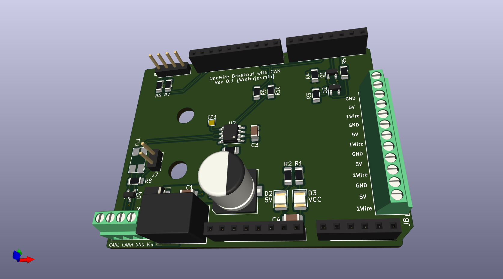
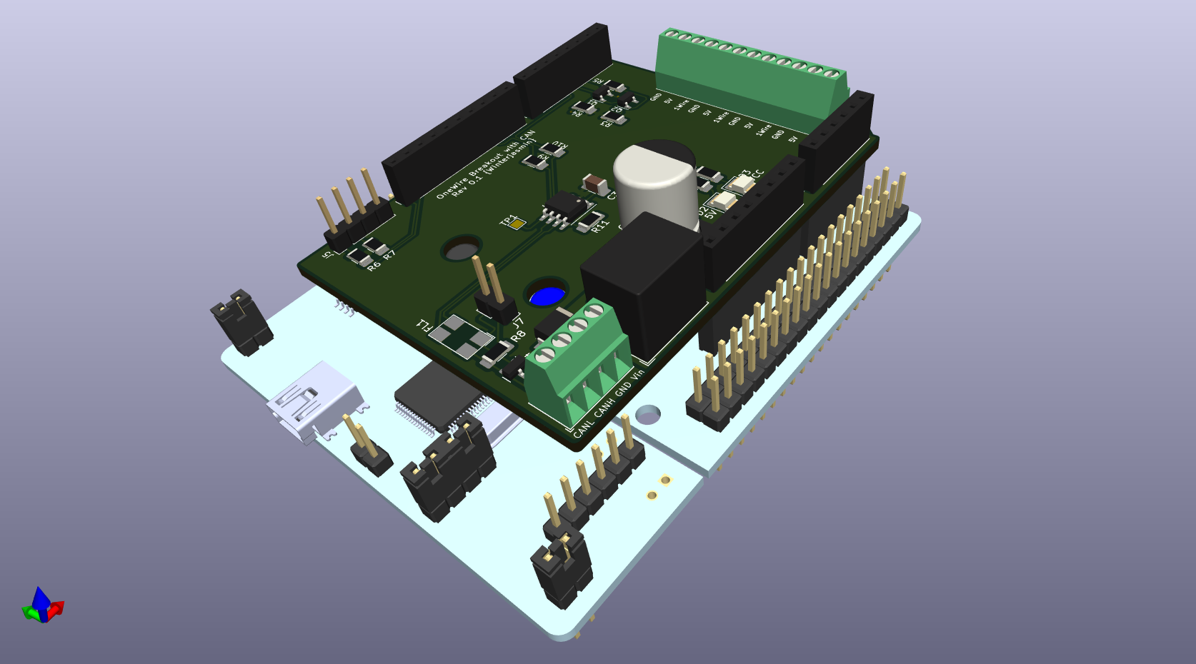
To study some of my testing done so far please have a look here.
| Qty | Value | Footprint | References |
|---|---|---|---|
| 3 | 100n | Capacitor_SMD:C_1206_3216Metric_Pad1.33x1.80mm_HandSolder | C1, C3, C4 |
| 2 | 0 | Resistor_SMD:R_1206_3216Metric_Pad1.30x1.75mm_HandSolder | R9, R10 |
| 2 | 10k | Resistor_SMD:R_1206_3216Metric_Pad1.30x1.75mm_HandSolder | R1, R5 |
| 2 | 47 | Resistor_SMD:R_1206_3216Metric_Pad1.30x1.75mm_HandSolder | R6, R7 |
| 2 | BC847 | Package_TO_SOT_SMD:SOT-23 | Q1, Q2 |
| 2 | LED_YE | LED_SMD:LED_1210_3225Metric_Pad1.42x2.65mm_HandSolder | D2, D3 |
| 1 | 100k | Resistor_SMD:R_1206_3216Metric_Pad1.30x1.75mm_HandSolder | R4 |
| 1 | 120 | Resistor_SMD:R_1206_3216Metric_Pad1.30x1.75mm_HandSolder | R8 |
| 1 | 22k | Resistor_SMD:R_1206_3216Metric_Pad1.30x1.75mm_HandSolder | R11 |
| 1 | 3k3 | Resistor_SMD:R_1206_3216Metric_Pad1.30x1.75mm_HandSolder | R2 |
| 1 | 47u | Capacitor_SMD:CP_Elec_10x12.5 | C2 |
| 1 | 4k7 | Resistor_SMD:R_1206_3216Metric_Pad1.30x1.75mm_HandSolder | R3 |
| 1 | Analog | Connector_PinSocket_2.54mm:PinSocket_1x06_P2.54mm_Vertical | J3 |
| 1 | Conn_01x02_Male | Connector_PinHeader_2.54mm:PinHeader_1x02_P2.54mm_Vertical | J7 |
| 1 | Conn_01x04 | TerminalBlock_Phoenix:TerminalBlock_Phoenix_MPT-0,5-4-2.54_1x04_P2.54mm_Horizontal | J6 |
| 1 | Conn_01x04 | Connector_PinHeader_2.54mm:PinHeader_1x04_P2.54mm_Vertical | J5 |
| 1 | Conn_01x12 | TerminalBlock_Phoenix:TerminalBlock_Phoenix_MPT-0,5-12-2.54_1x12_P2.54mm_Horizontal | J8 |
| 1 | Digital/PWM | Connector_PinSocket_2.54mm:PinSocket_1x08_P2.54mm_Vertical | J4 |
| 1 | Digital/PWM | Connector_PinSocket_2.54mm:PinSocket_1x10_P2.54mm_Vertical | J2 |
| 1 | MCP2551-I-SN | Package_SO:SOIC-8_3.9x4.9mm_P1.27mm | U2 |
| 1 | Power | Connector_PinSocket_2.54mm:PinSocket_1x08_P2.54mm_Vertical | J1 |
| 1 | R-78E9.0-0.5 | Converter_DCDC:Converter_DCDC_RECOM_R-78E-0.5_THT | U1 |
| 1 | SP0502BAHT | Package_TO_SOT_SMD:SOT-23 | D4 |
| 1 | TestPoint_Probe | TestPoint:TestPoint_Pad_1.5x1.5mm | TP1 |
| 1 | US1D | Diode_SMD:D_SMA | D1 |
| 1 | WE_LineFilter_CAN | CommonUsedElemetsLMWB:L_CommonModeChoke_CAN_lmwb | FL1 |

drfailov/DRM_Watch_v3
DRM Watch 3 - Наручний годинник з дисплеєм SHARP Memory LCD

LMWB/Pasta-alla-Norma
Circular shaped RGB-LED PCB with integrated Microcontroller and EEPROM


martinribelotta/h730duino
STM32H7 Arduino form factor and software compatible board


It measures 68.6 × 53.3 mm and has 2 copper layers, 1.6 mm thick.
33 parts, built around the MCP2551-I/SN-HG, R-78E9.0-0.5, BC847 and SP0502BAHTG. The full list of its parts is on this page, with links to each part's symbol and footprint where PCBKit's library has them.
From the LMWB/Quattro-Formaggi repository on GitHub, at the commit this page was made from: the board is Hardware/lmwb_ds18b20.kicad_pcb and its schematic Hardware/lmwb_ds18b20.kicad_sch. PCBKit opens the board in the browser, with nothing to install.
Its repository publishes it under the MIT licence: you may reuse it on that licence's terms (keep the author's notice, and for a copyleft licence share your changes alike).