GNSS-synchronized alarm clock — custom SAMD51J20A board with nPM1300 Li-ion power (USB-C), offline timezone+DST from coordinates, LVGL 9 on a 428x142 TFT, WAV alarm tunes over USB, battery-backed RTC
Samd51 gps alarm clock is an open-source printed circuit board by KrHaaland, from the KrHaaland/GNSS_Alarm_Clock repository on GitHub. It is a 2-layer board of 80 × 50 mm with 162 parts on 145 nets, routed with 1,089 tracks and 152 vias.
It is built around the ATSAMD51J19A-AUT-EFP, L86-M33 and IRLML6344TRPBF, with the 24LC512-I/P, LIS3DH and RV-3028-C7 among its other parts. Its parts include 62 resistors, 35 diodes, 26 capacitors, 14 ICs and 5 connectors. It belongs with the lEDs and displays and radio and wireless boards and the SAM D and SAM boards of this library.
Firmware for the custom SAMD51 alarm-clock board (Adafruit Metro M4
compatible), designed in HARDWARE/ (KiCad). Two board revisions share one
firmware:
v2 (current) — SAMD51J20A, nPM1300 PMIC with Li-ion charging and
USB-C, LM3671 3.3 V + TPS61023 5 V boost, battery-backed RTC, MCU core on
its internal buck regulator. See
HARDWARE_V2.md and ADR-0014/0015.
Default build: metro_m4_j20.
v1 (prototype) — SAMD51J19A, LTC3226 + supercaps (design in
HARDWARE_OLD/). Build: adafruit_metro_m4. The firmware detects the
PMIC at runtime and degrades gracefully either way.
Time is set automatically from GNSS, the timezone (with DST) is derived offline
from the GNSS coordinates and saved to flash so it stays correct indoors, and
alarms drive an LED light-show + a tune through a class-D amp. The UI is LVGL on
a 428×142 color TFT driven by four buttons.
Current state: firmware is feature-complete and running on hardware —
display, GNSS time/timezone, alarms, audio, tunes-over-USB, settings, modes
(speedometer/altimeter/USB-gamepad) and the RV-3028 RTC (hand-fitted; it was
missing from the prototype) all work. See STATUS.md and
HARDWARE_REVIEW.md.
CI: GitHub Actions builds all firmware targets + runs the native test suite on every push
What it does
Time: The Quectel L86 GNSS receiver (Serial1, 9600 NMEA, RMC+GGA @1 Hz
plus GSV satellites-in-view every 5 s for the Sky-view screen, TinyGPS++ +
a small in-house GSV parser) provides UTC. The clock is a millis()-anchored UTC counter
disciplined by GNSS (re-syncs hourly / on ≥2 s drift) and backed by the
RV-3028-C7 RTC (I²C 0x52), whose VBACKUP sits on the battery (v2; the
v1 prototype used the supercap rail) so it holds time through power loss. On boot the clock starts from the RTC
immediately and refines from GNSS when a fix is available. A cold-start guard
rejects the L86's free-running "year-2080" date so garbage can't be written
into the backup RTC.
Timezone from coordinates: An embedded offline lookup (213-box table
covering every UTC zone worldwide — multi-zone countries split by region, plus
no-DST exceptions like Arizona / Saskatchewan / Queensland / Kaliningrad;
borders like US-zones and Afghanistan/Pakistan/India aligned to the real
meridians). Polygon zones are checked before the boxes: real IANA
timezone borders generated from timezone-boundary-builder data by
tools/gen_tz_polys.py (tunable resolution/flash budget; enclaves ordered
first), refinable by hand in tools/tz_polygon_editor.html (map GUI:
draw/edit vertices, probe a point, export the header). Two resolutions,
picked by flash size: v2/J20 gets the fine map
(src/TimezonePolyDataFine.h, ~1–2 km borders, 404 zones / 56k vertices,
~250 KB), v1/J19 the coarse one (src/TimezonePolyData.h, ~57 KB). Anything not inside a polygon or box falls back
to a whole-hour longitude estimate, so every coordinate resolves. Maps
the GNSS position to a
POSIX TZ string with DST rules (e.g. Oslo →
CET-1CEST,M3.5.0,M10.5.0/3). The result is persisted to internal flash,
so local time (including DST changes) stays correct after reboot even with no
fix indoors. A DST-aware POSIX evaluator (Timezone.*, host-unit-tested)
computes the offset. Manual zone override is available in the menu.
Alarms: Two independent alarms with per-weekday masks. On trigger:
the 34 LEDs (3 sections: left 10 / bottom 14 / right 10) run a chase at
full brightness from a battery-capable rail (v2: TPS61023 5 V boost;
v1: the LTC3226 supercap rail) — brightness never depends on the USB
supply. The light show is switchable per alarm (Lights in the alarm
editor; off = sound-only alarm),
a tune plays: a WAV from the QSPI flash drive, or one of 3 built-in
melodies, via DAC0 → TPA2016D2 class-D amp → speaker. WAVs pass a
200 Hz high-pass in firmware: sub-bass cost the most battery current
(speaker impedance minimum) for the least sound (ADR-0010),
optional escalation: after N minutes unacknowledged, the power buzzer
joins in (v1 hardware only — v2 dropped the buzzer); auto-silence after
30 min.
Snooze: short-press any button, or double-tap the clock (LIS3DH).
Stop: long-press any button.
UI: LVGL 9.5 on an NV3007 color TFT (see below), driven by the 4
buttons above the display: [Back/Menu] [Prev/–] [Next/+] [OK]. Screens:
clock, menu, alarm-edit, time & zone, display, tunes, system-info,
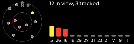
sky view (GSV polar plot + SNR bars — indoor antenna-placement aid),
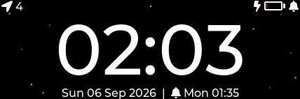
ringing. A true-black theme keeps the panel dark. Optional starry night:
twinkling stars behind the clock digits between 22:00 and 06:00.
Modes (Menu → Mode, cycles in place; alarms keep working in all of them):
Alarm clock — the normal HH:MM face.
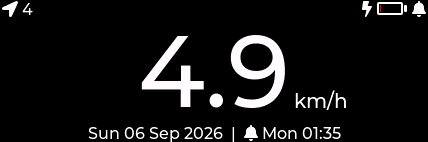
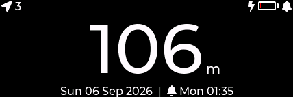
Speedometer — the big figure shows GNSS ground speed in km/h.
Altimeter — GNSS altitude in m (MSL).
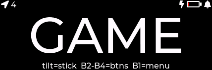
Game mode — the LIS3DH becomes a USB HID gamepad: tilt = stick
X/Y, B2–B4 = buttons 1–3 (B1 keeps its menu role). The HID interface is
always in the descriptor; it only sends reports in this mode.
Power (v2): the nPM1300 is driven end-to-end — input limit follows the
USB-C CC advertisement (500 mA on PC ports, 1500 mA on real chargers,
re-applied instantly on replug via the PMIC's IRQ line on PA04), charging
400/800 mA to 4.10 V under an 80/70 °C die thermostat, live battery
current on the Battery screen, a drawn SoC gauge on the clock face
(ADR-0014/0016), and a low-battery policy: ship mode below 3.40 V (never
during an alarm), fullscreen LOW BATTERY on a too-early wake, manual
Shutdown in the menu — BUTTON1 or USB wakes it, the RTC keeps time
throughout. The volume ceiling is bench-tuned to the PMIC's 1000 mA
battery discharge limit (IBATLIM) — exceeding it collapses VSYS and
resets the device, so max volume (+7 dBV limiter) + LED chase stays under
it with margin (ADR-0010/0014).
Tune upload: the QSPI flash appears as a USB flash drive (TUNES) —
drag & drop .wav files (PCM, 8/16-bit, mono/stereo, 8–48 kHz).
Screenshots
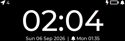
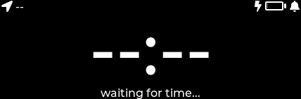
Grabbed from the live firmware over USB serial (tools/screenshot.py).
Clock face — battery gauge, charge bolt, alarm bell
Starry night (22:00–06:00)
First boot, no RTC/GNSS time yet
Sky view — GSV polar plot + SNR bars
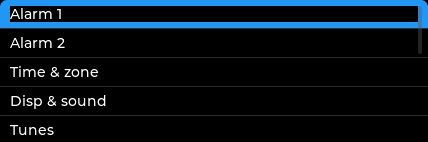
Main menu
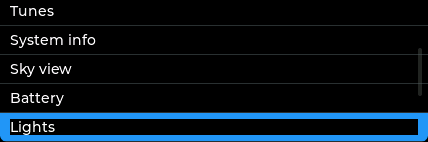
…scrolled
Speedometer mode (GNSS)
Altimeter mode (GNSS)
Game mode — USB HID gamepad
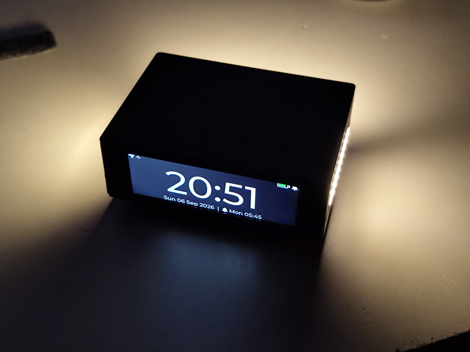
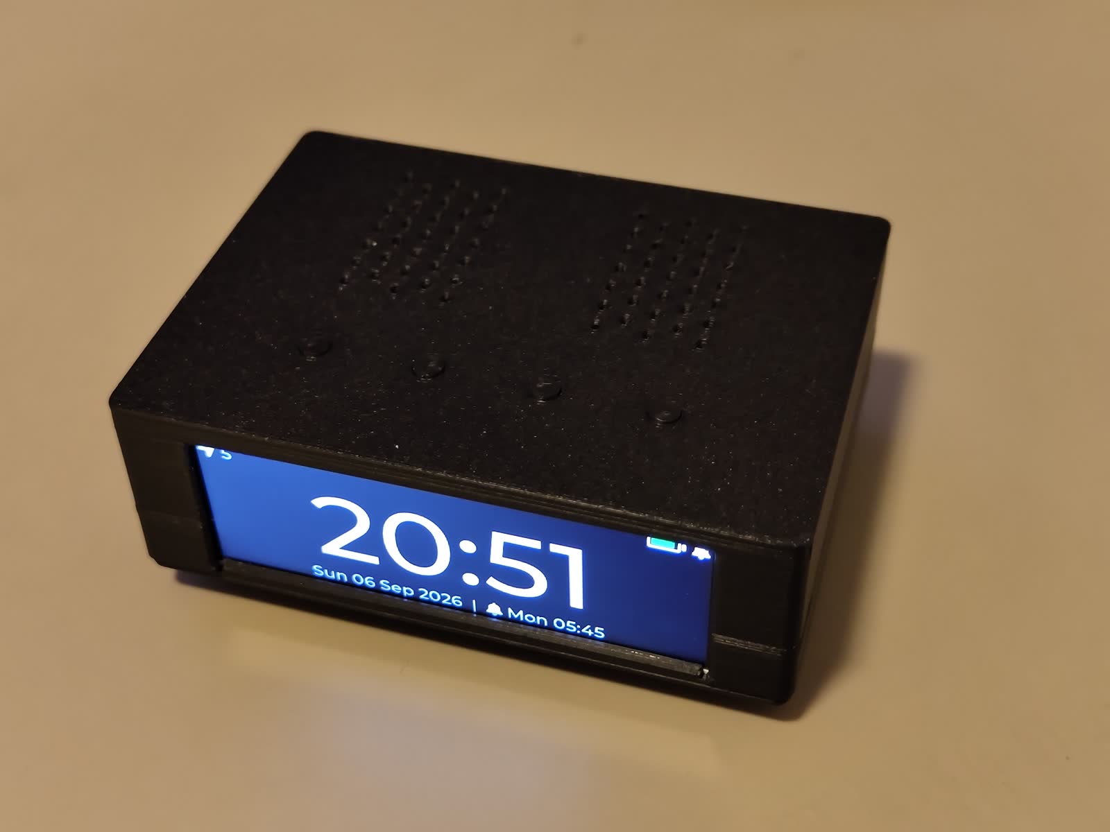
The 3D-printed enclosure
Display (NV3007)
The panel is an NV3007 color TFT (Newvision), native 142×428 bar type,
driven landscape 428×142. Driver: src/DisplayNV3007.cpp.
(The v1 prototype's ST7789 284×76 driver is kept in-tree — pick the panel via
DISPLAY SELECT in platformio.ini.)
Vendor init is mandatory: 0xFF 0xA5 unlocks the extended register page
(power/gamma/gate-driver/source-timing dump); without it the address engine
wraps writes linearly across the glass. 0xFF 0x00 returns to the DCS page.
Sequence cross-verified against five independent drivers (Arduino_GFX, LVGL
lv_nv3007, vendor reference, STM32 + esp_lcd ports).
GRAM is 168×428; the 142 visible columns are inset 12/14. Landscape
(MADCTL 0xA0, flipped 180° to match the enclosure mounting) puts the
inset on RASET: NV_Y_OFFSET 12 (unflipped 0x60 → 14). Inversion OFF.
SPI mode 0 (an NV3007 quirk — ST7789 setups often run mode 3), 30 MHz
(SERCOM2 re-clocked from the 120 MHz GCLK0 — the default 48 MHz source
quantizes to 24 MHz max). Pixels stream via an async DMA flush with double
buffering (ADR-0012, superseding ADR-0002's DMA ban): LVGL renders the
next strip while the DMAC streams the previous one, and the completion IRQ
hands the buffer back. Falls back to a synchronous DRE-paced register loop
if the DMA channel is unavailable. Full frame ~26 ms on the wire, hidden
behind rendering.
Known silicon quirk: tiny partial writes can half-light adjacent pixels for
RGB channel values 1–31 against black; LVGL's strip-sized flushes avoid it.
Backlight D11/PA19, PWM-dimmed; shake-to-wake; DISPLAY_SELFTEST bring-up
pattern test (colors/border/origin) as before.
The clock figure uses a generated 100 px Montserrat subset
(src/font_clock_100.c, 18 chars) — replacing the full 48 px font actually
shrank flash by 67 KB (ADR-0011).
Storage decision
The board has two candidate "EEPROMs" for tunes: the 24LC512 (64 KB, I²C) and a
QSPI serial flash. The firmware uses the QSPI flash (exposed as the USB
drive): far larger, faster, on the standard Metro M4 QSPI pins, and it enables
the drag-and-drop workflow.
Settings are packed into the RV-3028 RTC's 43-byte user EEPROM.
Chosen because it survives firmware reflashes (the old internal-flash
emulation sat inside the app image and was wiped on every update), takes
~100k writes/byte, and frees the 24LC512 to be dropped from the hardware-v2
BOM (it still ACKs at 0x50 on v1 boards, unused). Verified on hardware:
settings survive both power cycles and reflashes.
RTC user-EEPROM memory map (38 of 43 bytes)
Space is won by not storing derived data: TZ strings re-derive at boot from
the stored position (or the manual GMT-ladder index), and alarm tune filenames
are stored as 16-bit FNV-1a hashes re-matched against the TUNES directory
(missing file → builtin melody). Multi-byte fields are little-endian.
Addr
Size
Field
0x00
2
Magic 'G' 'C'
0x02
1
Pack-format version (4) — older blocks (v1–v3) migrate in place at boot, nothing is reset
Manual zone index into TZ_TABLE (0xFF = none/auto)
0x09
1
Volume (0–10)
0x0A
1
Snooze minutes
0x0B
1
Buzzer escalation after N min (0 = off)
0x0C
1
Brightness
0x0D
2
Dim timeout, seconds (u16)
0x0F
1
Dim brightness
0x10
3
Snooze counter, all time (u24, caps at 16.7 M)
0x13
2
Snooze counter, this week (u16)
0x15
2
Week start, local epoch-day − 18262 (u16, base 2020-01-01)
0x17
7
Alarm 1: flags (b0 enabled, b1–2 ramp Off/15/30/60 s, b3–4 random ±0/1/5/9 min, b5 lights-OFF — inverted so old blocks read as on), hour, minute, daysMask, melodyId, tuneHash (u16)
0x1E
7
Alarm 2: same layout
0x25
1
Checksum (block sums to 0xFF) — written last, so a torn write invalidates the image
0x26
5
Free / future
RV-3028 EEPROM quirks (bench-found, handled in RtcRV3028.cpp): the
chip NACKs all I²C while its EEPROM engine runs — both during the
power-on auto-refresh (>100 ms) and in short windows after each programmed
byte. The driver therefore treats failed STATUS reads as "still busy"
(300 ms deadline), retries each byte transaction up to 5×, and read-back
verifies every written byte.
Flash BOM note: the schematic specifies a 4 MB Macronix MX25L3233F, but
assembled boards carry a 16 MB Winbond W25Q128 (JEDEC 0xEF4018). The driver
auto-detects the real chip via the library's default device list, so the true
size is used for the USB drive.
pio run                      # build (default env: adafruit_metro_m4)
pio test -e native           # host-side unit tests (timezone/DST engine)
MCU select (J19 / J20)
The prototype has a SAMD51J19A (512 KB flash, ~95% full); the next revision
uses a SAMD51J20A (1 MB flash, ~48% — same pinout). Pick the build in
platformio.ini (default_envs) or per-invocation:
env
MCU
notes
adafruit_metro_m4
J19A 512 KB
default (current prototype)
metro_m4_j20
J20A 1 MB
boards/samd51j20a_metro.json + ld/samd51j20a_*.ld
sim / sim_j20
either
+ serial GNSS simulator (-DGNSS_SIM)
sh
pio run -e metro_m4_j20 # J20 build; flash .pio/build/metro_m4_j20/firmware.bin @0x4000
J20 + stock bootloader: the Metro M4 UF2 bootloader is built for the
J19A and reads the "stay in bootloader" magic at its RAM top
(0x2002FFFC); a J20 app writes it at 0x2003FFFC, so the 1200-baud touch
used to land straight back in the app. tools/patch_tinyusb_power.py
patches the core's initiateReset() to write both addresses — USB
uploads now work on the J20 with the stock bootloader.
Two flashing paths:
A) USB (normal, no tools):pio run -e metro_m4_j20 -t upload —
1200-baud touch into the bootloader, bossac writes + verifies at 0x4000
(~4 s). Manual alternative: double-tap RESET to mount the METROM4BOOT
drive and drag firmware.uf2 onto it.
⚠️ Never flash the .elf over SWD. Its LOAD segment sits at address 0x0
and will overwrite the UF2 bootloader at flash start, bricking drag-and-drop
programming (recovery = re-flash the bootloader). Always flash the .bin at
0x4000. The bootloader region is additionally guarded by the
BOOTPROT fuse (16 KB) since a brownout-induced wild NVMCTRL write once
zeroed the bootloader's vector table (see docs/sessions/); clear it with
atsame5 bootloader 0 before intentional bootloader updates, restore with
atsame5 bootloader 16384.
pio device monitor -b 115200 opens the USB-CDC console. Sending ~ on
the console streams the next rendered frame as a screenshot —
python3 tools/screenshot.py grabs it and writes a PNG (used for the
documentation images; works on the live device, any screen).
USB identity
The app enumerates as 1209:0001 — "K. Haaland / GNSS Alarm Clock".
VID 0x1209 belongs to pid.codes (free USB IDs for
open-source hardware); 0x0001 is their official test PID, fine for
personal use — register a permanent PID via a pid.codes PR (requires a public,
OSI-licensed repo) before distributing hardware. Identity lives in
boards/samd51j19a_kh.json / boards/samd51j20a_metro.json. Bootloader mode
(double-tap reset) still enumerates as Adafruit 239A until a custom
uf2-samdx1 is built.
Simulated GNSS (env:sim)
To test the timezone/clock pipeline on-device without a real fix, build the
sim env — identical firmware plus -DGNSS_SIM (the L86 init is skipped and a
serial console feeds position/time):
sh
pio run -e sim -t upload      # or SWD-flash .pio/build/sim/firmware.bin @0x4000
pio device monitor -b 115200
Then type commands into the monitor:
text
pos 59.91 10.75              set a fix; resolves + applies the timezone
tz  -33.87 151.2             query a zone (Jan/Jul offset + DST), no state change
utc 2026 7 13 12 0 0         set the UTC clock so local time shows on the display
status                       print fix / UTC / local time / zone
nofix                        drop the simulated fix
pos also updates the on-screen clock's zone immediately, so you can watch the
display follow you around the globe. The sim code compiles to nothing in the
normal build — zero production-flash cost.
GNSS-synchronized alarm clock — custom SAMD51J20A board with nPM1300 Li-ion power (USB-C), offline timezone+DST from coordinates, LVGL 9 on a 428x142 TFT, WAV alarm tunes over USB, battery-backed RTC
It measures 80 × 50 mm and has 2 copper layers, 1.6 mm thick.
What parts does the Samd51 gps alarm clock use?
162 parts, built around the ATSAMD51J19A-AUT-EFP, L86-M33, IRLML6344TRPBF and 24LC512-I/P. The full list of its parts is on this page, with links to each part's symbol and footprint where PCBKit's library has them.
Where can I download the Samd51 gps alarm clock KiCad files?
From the KrHaaland/GNSS_Alarm_Clock repository on GitHub, at the commit this page was made from: the board is HARDWARE_OLD/samd51_gps_alarm_clock.kicad_pcb and its schematic HARDWARE/GNSS_Alarm_Clock.kicad_sch. PCBKit opens the board in the browser, with nothing to install.
Can I use the Samd51 gps alarm clock design in my own project?
Its repository states no licence, so its author keeps all rights: ask KrHaaland before reusing the design.