4 layers100 × 71 mm

 Keyaan-07/gps-rx
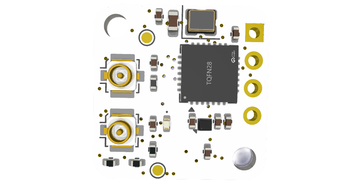
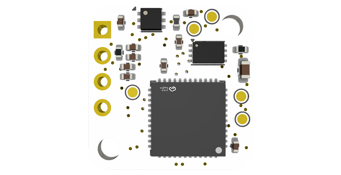
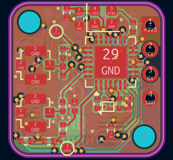
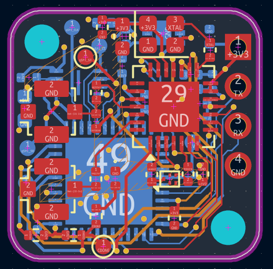
Gps rx is an open-source printed circuit board by Keyaan-07, from the Keyaan-07/gps-rx repository on GitHub. It is a 4-layer board of 16 × 16 mm with 45 parts on 62 nets, routed with 393 tracks and 52 vias.
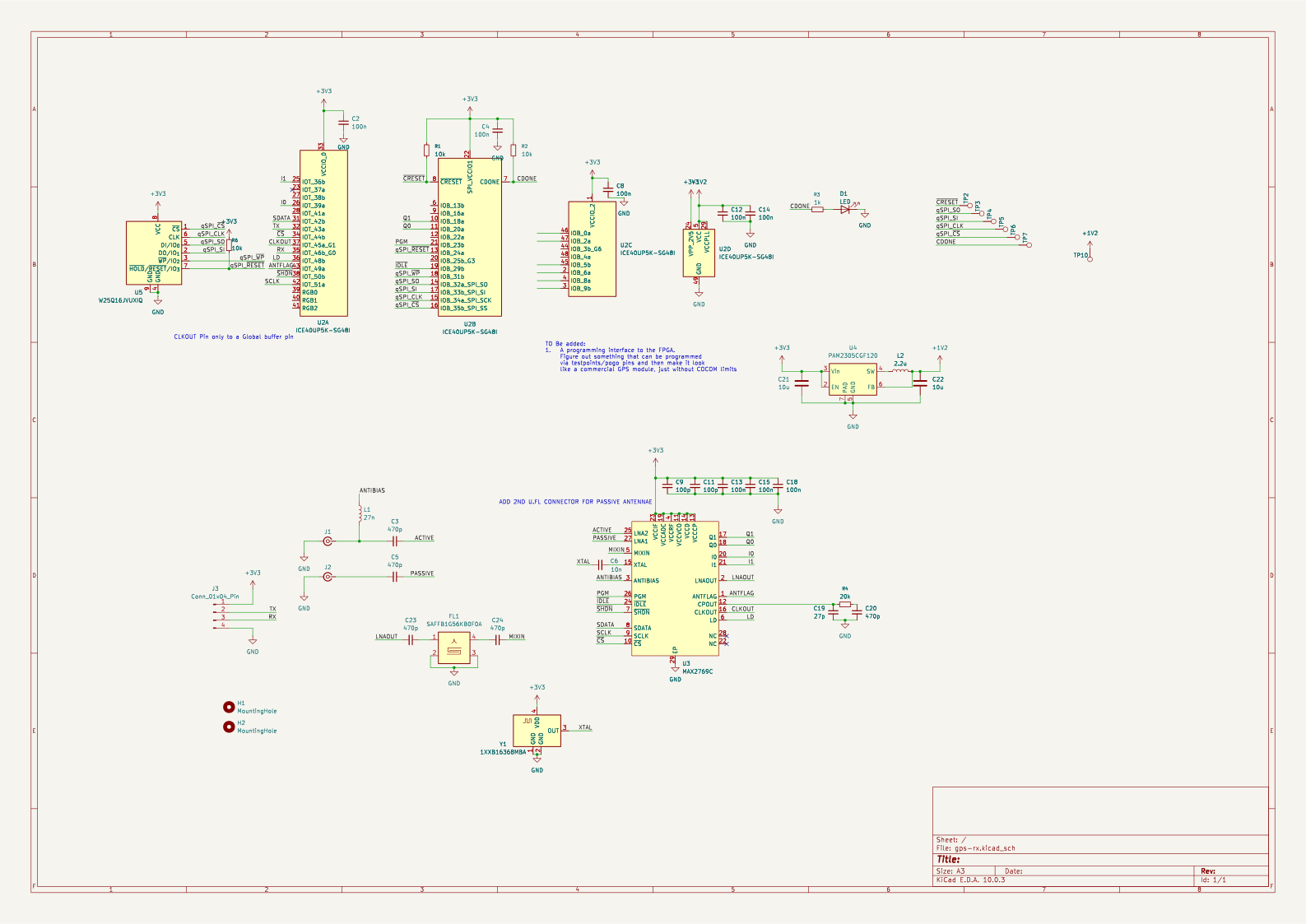
It is built around the ICE40UP5K-SG48I, MAX2769CETI+ and W25Q16JVUXIQ, with the 1XXB16368MBA and SAFFB1G56KB0F0A among its other parts. Its parts include 19 capacitors, 5 resistors, 4 ICs, 3 connectors and 2 inductors. It belongs with the radio and wireless boards and the FPGA and CPLD boards of this library.


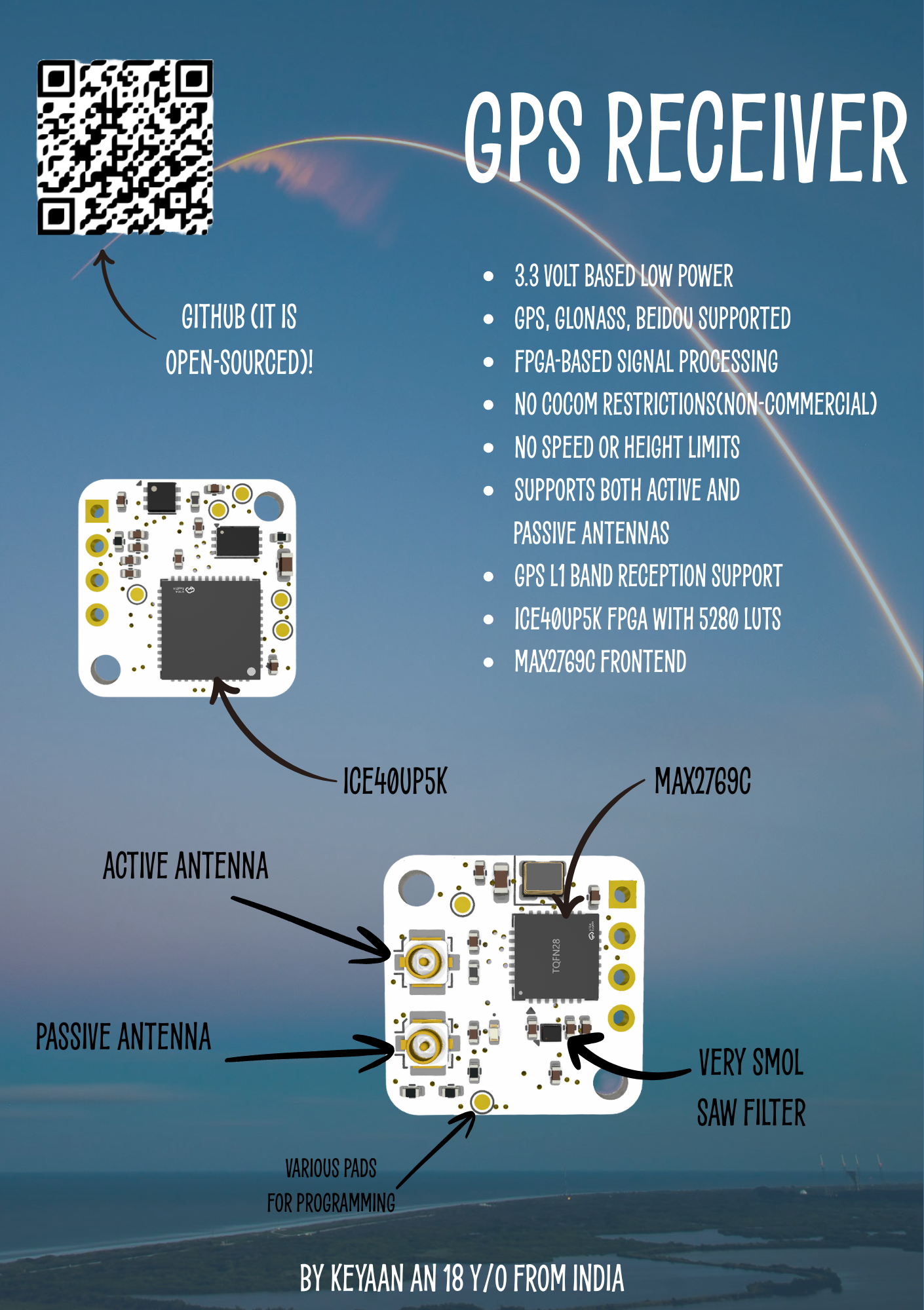
GPS-RX is a custom-hardware, low-power GPS receiver that is just 16x16mm in size. This receiver does not have any COCOM limits and is fully customisable. It uses UART to communicate with other external controllers and takes a 3.3 volt input. Unlike other GPS receivers, there are no speed or height based limits and can go to any height or any speeds. It is built like a really small module and can be built and assembled by anyone and used basically everywhere. I built this project to learn verilog and also because this seems really cool! The ice40up5k from lattice semiconductor is the FPGA that processes the GPS signals.
| Designator | Function | Value | Footprint | Quantity | Price | Amount | Link |
|---|---|---|---|---|---|---|---|
| PCB+stencil | PCB+stencil | Front and back both | 16x16mm | 5+2 | 2.1+6.14 | 8.24 | https://jlcpcb.com/ |
| C11, C9 | Capacitor | 100p | 402 | 50 | 0.0112 | 0.56 | https://www.lcsc.com/product-detail/C77177.html |
| C12, C13, C14, C15, C18, C2, C4, C8 | Capacitor | 100n | 402 | 100 | 0.0067 | 0.67 | https://www.lcsc.com/product-detail/C60474.html |
| C19 | Capacitor | 27p | 402 | 100 | 0.0036 | 0.36 | https://www.lcsc.com/product-detail/C1557.html |
| C20, C23, C24, C3, C5 | Capacitor | 470p | 402 | 50 | 0.0176 | 0.88 | https://www.lcsc.com/product-detail/C76971.html |
| C21, C22 | Capacitor | 10u | 603 | 10 | 0.04 | 0.4 | https://www.lcsc.com/product-detail/C18164635.html |
| C6 | Capacitor | 10n | 402 | 100 | 0.0041 | 0.41 | https://www.lcsc.com/product-detail/C5137480.html |
| D1 | LED | LED | 402 | 20 | 0.0357 | 0.714 | https://www.lcsc.com/product-detail/C5123495.html |
| FL1 | Filter | SAFFB1G56KB0F0A | Filter_1109-5_1.1x0.9mm | 10 | 0.072 | 0.72 | https://www.lcsc.com/product-detail/C91647.html |
| J1, J2 | Connector | Conn_Coaxial_Small | U.FL_Molex_MCRF_73412-0110_Vertical | 5 | 0.1019 | 0.51 | https://www.lcsc.com/product-detail/C88374.html |
| J3 | Connector | Conn_01x04_Pin | PinHeader_1x04_P2.54mm_Vertical | 20 | 0.026 | 0.52 | https://www.lcsc.com/product-detail/C2691448.html |
| L1 | Inductor | 27n | 402 | 10 | 0.09 | 0.9 | https://www.lcsc.com/product-detail/C882469.html |
| L2 | Inductor | 2.2u | 402 | 5 | 0.304 | 1.52 | https://www.lcsc.com/product-detail/C3911260.html |
| R1, R2, R6 | Resistor | 10k | 402 | 100 | 0.0025 | 0.25 | https://www.lcsc.com/product-detail/C2906861.html |
| R3 | Resistor | 1k | 402 | 100 | 0.0041 | 0.41 | https://www.lcsc.com/product-detail/C106235.html |
| R4 | Resistor | 20k | 402 | 100 | 0.005 | 0.5 | https://www.lcsc.com/product-detail/C93942.html |
| U2 | FPGA | ICE40UP5K-SG48I | QFN-48-1EP_7x7mm_P0.5mm_EP5.6x5.6mm | 1 | 8.56 | 8.56 | https://www.lcsc.com/product-detail/C2678152.html |
| U3 | GPS Frontend | MAX2769C | TQFN-28-1EP_5x5mm_P0.5mm_EP3.25x3.25mm | 1 | 3.24 | 3.24 | https://www.lcsc.com/product-detail/C400150.html |
| U4 | Buck | PAM2305CGF120 | DFN-6-1EP_2x2mm_P0.65mm_EP1x1.6mm | 5 | 0.198 | 0.99 | https://www.lcsc.com/product-detail/C110511.html |
| U5 | qSPI storage | W25Q16JVUXIQ | Winbond_USON-8-1EP_3x2mm_P0.5mm_EP0.2x1.6mm | 1 | 1.62 | 1.62 | https://www.lcsc.com/product-detail/C2843335.html |
| Y1 | TXCO Crystal 16.368MHz | 1XXB16368MBA | Crystal_SMD_2520-4Pin_2.5x2.0mm | 1 | 0.95 | 0.95 | https://www.lcsc.com/product-detail/C213423.html |
| Hot air gun | For soldering dual sided PCB | 1 | 45.18 | 45.18 | https://robu.in/product/yihua-959d-ii-hot-air-gun-with-easy-nozzle-plug-pull-storage-stand-desoldering-smd-rework-soldering-station/ | ||
| Subtotal | 69.864 | ||||||
| JLC Shipping | 13 | ||||||
| LCSC Shipping | 9.26 | ||||||
| Total | 92.124 |
| Qty | Value | Footprint | References |
|---|---|---|---|
| 8 | 100n | Capacitor_SMD:C_0402_1005Metric | C2, C4, C8, C12, C13, C14, C15, C18 |
| 7 | TestPoint | TestPoint:TestPoint_Pad_D1.0mm | TP2, TP3, TP4, TP5, TP6, TP7, TP10 |
| 5 | 470p | Capacitor_SMD:C_0402_1005Metric | C3, C5, C20, C23, C24 |
| 3 | 10k | Resistor_SMD:R_0402_1005Metric | R1, R2, R6 |
| 2 | 100p | Capacitor_SMD:C_0402_1005Metric | C9, C11 |
| 2 | 10u | Capacitor_SMD:C_0603_1608Metric | C21, C22 |
| 2 | Conn_Coaxial_Small | Connector_Coaxial:U.FL_Molex_MCRF_73412-0110_Vertical | J1, J2 |
| 2 | MountingHole | MountingHole:MountingHole_2.2mm_M2 | H1, H2 |
| 1 | 10n | Capacitor_SMD:C_0402_1005Metric | C6 |
| 1 | 1XXB16368MBA | Crystal:Crystal_SMD_2520-4Pin_2.5x2.0mm | Y1 |
| 1 | 1k | Resistor_SMD:R_0402_1005Metric | R3 |
| 1 | 2.2u | Inductor_SMD:L_0402_1005Metric | L2 |
| 1 | 20k | Resistor_SMD:R_0402_1005Metric | R4 |
| 1 | 27n | Inductor_SMD:L_0402_1005Metric | L1 |
| 1 | 27p | Capacitor_SMD:C_0402_1005Metric | C19 |
| 1 | Conn_01x04_Pin | Connector_PinHeader_2.54mm:PinHeader_1x04_P2.54mm_Vertical | J3 |
| 1 | ICE40UP5K-SG48I | Package_DFN_QFN:QFN-48-1EP_7x7mm_P0.5mm_EP5.6x5.6mm | U2 |
| 1 | LED | LED_SMD:LED_0402_1005Metric | D1 |
| 1 | MAX2769C | Package_DFN_QFN:TQFN-28-1EP_5x5mm_P0.5mm_EP3.25x3.25mm | U3 |
| 1 | PAM2305CGF120 | Package_DFN_QFN:DFN-6-1EP_2x2mm_P0.65mm_EP1x1.6mm | U4 |
| 1 | SAFFB1G56KB0F0A | Filter:Filter_1109-5_1.1x0.9mm | FL1 |
| 1 | W25Q16JVUXIQ | Package_SON:Winbond_USON-8-1EP_3x2mm_P0.5mm_EP0.2x1.6mm | U5 |


TobleMiner/ublox-M8030-KT-breakout
Breakout for the bare UBX-M8030-KT chip. Supports pin compatible chips from M6, M7 and M8 generations. JLCSMT assembly supported


im-tomu/fomu-hardware
Tomu FPGA (Fomu for short), a FPGA which fits inside your USB port!


It measures 16 × 16 mm and has 4 copper layers, 1.06 mm thick.
45 parts, built around the ICE40UP5K-SG48I, MAX2769CETI+, W25Q16JVUXIQ and 1XXB16368MBA. The full list of its parts is on this page, with links to each part's symbol and footprint where PCBKit's library has them.
From the Keyaan-07/gps-rx repository on GitHub, at the commit this page was made from: the board is hardware/gps-rx.kicad_pcb and its schematic hardware/gps-rx.kicad_sch. PCBKit opens the board in the browser, with nothing to install.
Its repository states no licence, so its author keeps all rights: ask Keyaan-07 before reusing the design.