4 layers17.8 × 38.1 mm

 daglem/reDIP-SID121
MOS 6581 / 8580 SID FPGA emulation platform
ReDIP SID is an open-source printed circuit board by daglem, from the daglem/reDIP-SID repository on GitHub. It is a 4-layer board of 17.8 × 38.1 mm with 103 parts on 103 nets, routed with 1,168 tracks and 124 vias.
It is built around the ICE40UP5K-SG48I, SGTL5000XNLA3 and W25Q128JVPIM, with the APS6404L-3SQR-SN, NUF2042XV6 and ASCO-24.000MHZ-EK-T3 among its other parts. Its parts include 25 capacitors, 23 resistors, 11 ICs, 6 connectors and 1 diode. It belongs with the FPGA and CPLD boards of this library.


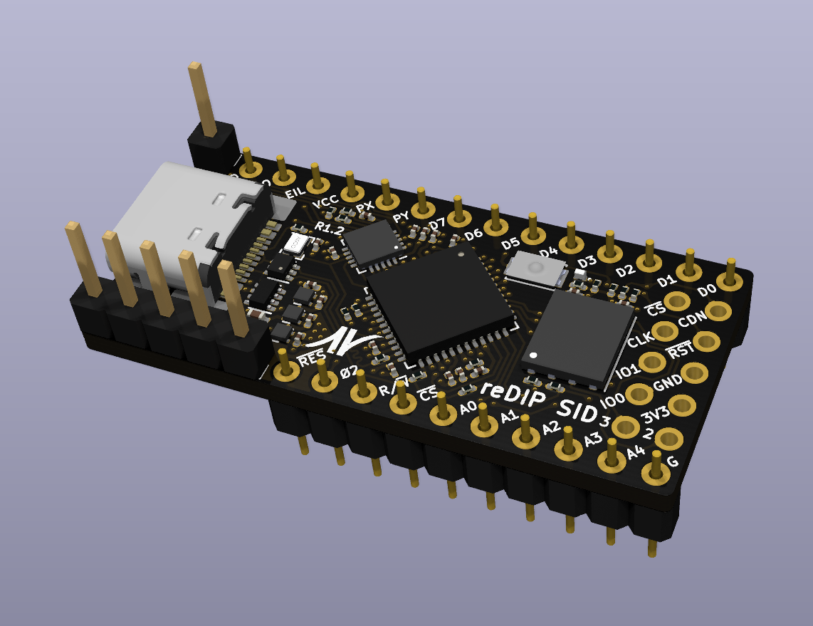
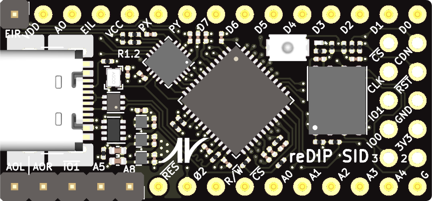
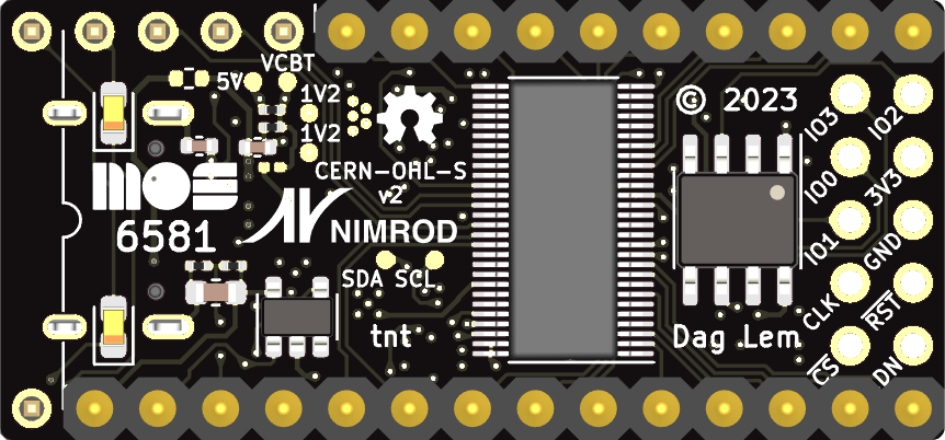
The reDIP SID is an open source hardware development board which combines the following in a DIP-28 size package:
The reDIP SID provides a fully functional open source hardware platform for MOS 6581/8580 SID emulation.
The reDIP SID also aims to be a good no-frills generic choice for FPGA projects which may find use for audio and/or 5V tolerant I/O - it should be ideal for for e.g. retro computer and synthesizer projects.
Designs for the iCE40UP5K FPGA can be processed by yosys and nextpnr.
The board is supported by the DFU Nitro Bootloader, facilitating simple updates over USB using e.g. dfu-util.
All FPGA header I/O is 5V tolerant, and can drive 5V TTL. JP1 can be shorted to make the 5V input pin bidirectional, e.g. to power 5V TTL devices from USB VBUS.
Note that the line inputs are not AC coupled - AC coupling must be externally added for audio applications. Without external AC coupling, the line inputs can conceivably be used as generic ADCs.
The 12V / 9V input is connected to the SGTL5000 mic input via a 1/6 ratio voltage divider.
A separate header footprint is provided for (Q)SPI peripherals / flash programming, with pinout borrowed from the iCEBreaker Bitsy.
The header provides a 3.3V output, which may be used to power external devices. The 3.3V rail is supplied by a 700mA LDO.
The board is fully pin compatible with the venerable MOS 6581/8580 SID sound chip.
The board features three additional address pins which may be connected to the Commodore 64, in order to make a second SID chip appear e.g. at address D420, D500, or DE00.
There is also an additional EXT IN audio input pin for a second SID chip, and separate stereo line output pins which may be connected directly to audio equipment. Either the SID GND pin or GND on the programming header may be used as audio ground.
Cycle accurate emulation of the SID chip has been implemented in gateware.
Big thanks go to Sylvain "tnt" Munaut, who has not only implemented support for the reDIP SID in his Nitro Bootloader, but has also identified shortcomings, suggested feature improvements, and provided invaluable help to ensure that the board actually works.
Thanks must also go to Aidan Dodds and Paul Sajna for putting the first prototype through its paces working on Dodds' icesid, with guidance from Munaut.
| Qty | Value | Footprint | References |
|---|---|---|---|
| 19 | SolderMask_D0.25mm | reDIP:SolderMask_D0.25mm | SolderMask_D0.25mm, SolderMask_D0.25mm, SolderMask_D0.25mm, SolderMask_D0.25mm, SolderMask_D0.25mm, SolderMask_D0.25mm, SolderMask_D0.25mm, SolderMask_D0.25mm, SolderMask_D0.25mm, SolderMask_D0.25mm, SolderMask_D0.25mm, SolderMask_D0.25mm, SolderMask_D0.25mm, SolderMask_D0.25mm, SolderMask_D0.25mm, SolderMask_D0.25mm +3 |
| 12 | 0.1uF | Capacitor_SMD:C_0201_0603Metric | C9, C10, C11, C12, C17, C18, C19, C20, C21, C22, C24, C25 |
| 6 | 1uF | Capacitor_SMD:C_0201_0603Metric | C4, C6, C7, C8, C16, C23 |
| 6 | TestPoint | reDIP:TestPoint_Pad_D0.75mm | TP1, TP2, TP3, TP4, TP5, TP6 |
| 5 | 10k | Resistor_SMD:R_0201_0603Metric | R11, R16, R17, R18, R22 |
| 5 | SolderMask_D0.5mm | reDIP:SolderMask_D0.5mm | SolderMask_D0.5mm, SolderMask_D0.5mm, SolderMask_D0.5mm, SolderMask_D0.5mm, SolderMask_D0.5mm |
| 4 | 1uF | Capacitor_SMD:C_0402_1005Metric | C1, C2, C3, C5 |
| 4 | 2.2k | Resistor_SMD:R_0201_0603Metric | R4, R5, R15, R19 |
| 3 | 20k | Resistor_SMD:R_0201_0603Metric | R8, R9, R10 |
| 2 | 0 | Resistor_SMD:R_0201_0603Metric | R20, R21 |
| 2 | 10uF | Capacitor_Tantalum_SMD:CP_EIA-1608-08_AVX-J | C14, C15 |
| 2 | 5.1k | Resistor_SMD:R_0201_0603Metric | R12, R13 |
| 2 | NCP115AMX120TCG | onsemi:CASE_711AJ_1.0x1.0mm_P0.65mm | U1, U3 |
| 1 | 1.5k | Resistor_SMD:R_0201_0603Metric | R6 |
| 1 | 100 | Resistor_SMD:R_0201_0603Metric | R14 |
| 1 | 100k | Resistor_SMD:R_0201_0603Metric | R7 |
| 1 | 1k | Resistor_SMD:R_0201_0603Metric | R1 |
| 1 | 1uF | Capacitor_SMD:C_0603_1608Metric | C13 |
| 1 | 22 | Resistor_SMD:R_0201_0603Metric | R23 |
| 1 | 6.2k | Resistor_SMD:R_0201_0603Metric | R3 |
| 1 | APS6404L-3SQR | Package_SO:SOP-8_3.9x4.9mm_P1.27mm | U9 |
| 1 | ASCO-24.000MHZ-EK-T3 | reDIP:Oscillator_SMD-4Pin_1.6x1.2mm | X1 |
| 1 | Conn_01x01 | reDIP:PinHeader_1x01_P2.54mm_Vertical | J1 |
| 1 | Conn_01x05 | reDIP:PinHeader_1x05_P2.54mm_Vertical | J2 |
| 1 | Conn_01x10 | reDIP:PinHeader_1x10_P2.54mm_Vertical_Machined | J4 |
| 1 | Conn_01x14 | reDIP:PinHeader_1x14_P2.54mm_Vertical_Machined | J3 |
| 1 | Conn_02x05_Odd_Even | reDIP:PinHeader_2x05_P2.54mm_Vertical | J6 |
| 1 | G*** | reDIP:MOS-logo | MOS logo |
| 1 | ICE40UP5K-SG48I | Package_DFN_QFN:QFN-48-1EP_7x7mm_P0.5mm_EP5.6x5.6mm | U11 |
| 1 | KXT311LHS | CK:SW_SPST_CK_KXT3 | SW1 |
| 1 | LM66200DRLR | reDIP:SOT-5X3 | U4 |
| 1 | MCP6H01T-E/OT | reDIP:SOT-23-5 | U8 |
| 1 | NC | Resistor_SMD:R_0201_0603Metric | R2 |
| 1 | NCP167AMX330TBG | onsemi:CASE_711AJ_1.0x1.0mm_P0.65mm | U2 |
| 1 | NUF2042XV6 | reDIP:SOT-563 | U7 |
| 1 | SGTL5000XNLA3 | Package_DFN_QFN:QFN-20-1EP_3x3mm_P0.4mm_EP1.65x1.65mm | U6 |
| 1 | SML-LX0201UPGC-TR | Lumex:SML-LX0201 | D1 |
| 1 | SN74CBT16211CDGVR | TI:Texas_TVSOP-56_4.4x11.3mm_P0.4mm | U5 |
| 1 | SolderJumper_2_Open | Resistor_SMD:R_0402_1005Metric | JP1 |
| 1 | USB4105-GF-A | HRO:USB_C_Receptacle_HRO_TYPE-C-31-M-12 | J5 |
| 1 | W25Q128JVPIM | Package_SON:WSON-8-1EP_6x5mm_P1.27mm_EP3.4x4.3mm | U10 |
The 100 most common of 103 parts.


anticitizn/p4eregrine
All-in-one ESP32 P4-based drone ESC, flight controller, and video processor


enkhbold470/ice-core
iCE40UP5K FPGA board with 8 MB PSRAM and three Pmods, programmed over USB-C by an RP2040. 6-layer KiCad 10 board.


jayis1/hacker-devices
Full-cycle hardware designs for security research devices — each device is a subfolder with its own README, schematics, PCB layout, and software stack

It measures 17.8 × 38.1 mm and has 4 copper layers, 1.6 mm thick.
103 parts, built around the ICE40UP5K-SG48I, SGTL5000XNLA3, W25Q128JVPIM and APS6404L-3SQR-SN. The full list of its parts is on this page, with links to each part's symbol and footprint where PCBKit's library has them.
From the daglem/reDIP-SID repository on GitHub, at the commit this page was made from: the board is hardware/reDIP-SID.kicad_pcb and its schematic hardware/reDIP-SID.kicad_sch. PCBKit opens the board in the browser, with nothing to install.
Its repository states no licence, so its author keeps all rights: ask daglem before reusing the design.