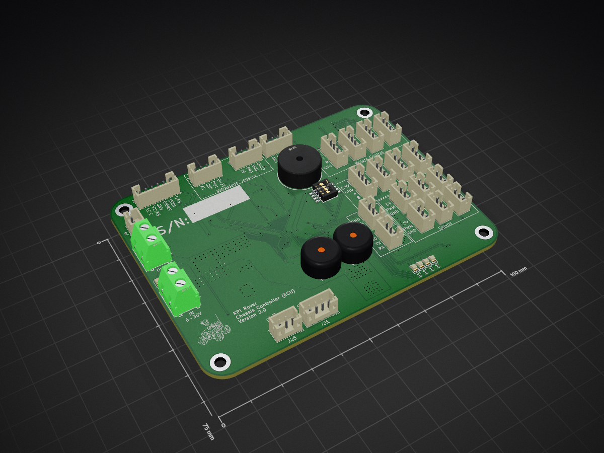
| 21 | 100nF | Capacitor_SMD:C_0805_2012Metric | C1, C2, C10, C12, C14, C17, C19, C21, C22, C23, C24, C26, C29, C30, C31, C32 +5 |
| 12 | 4.7k | Resistor_SMD:R_0805_2012Metric | R22, R23, R24, R25, R26, R27, R28, R29, R30, R31, R36, R37 |
| 12 | Conn_01x04_Pin | Connector_JST:JST_PH_B4B-PH-K_1x04_P2.00mm_Vertical | J2, J7, J8, J9, J10, J12, J13, J14, J15, J16, J17, J21 |
| 10 | 0 | Resistor_SMD:R_0805_2012Metric | R38, R39, R40, R46, R47, R48, R49, R50, R51, R52 |
| 9 | 10uF | Capacitor_SMD:C_0805_2012Metric | C11, C13, C18, C20, C25, C27, C35, C36, C37 |
| 9 | Conn_01x03_Pin | Connector_JST:JST_PH_B3B-PH-K_1x03_P2.00mm_Vertical | J5, J6, J18, J19, J20, J22, J23, J24, J25 |
| 8 | 10k | Resistor_SMD:R_0805_2012Metric | R2, R18, R19, R20, R21, R32, R33, R34 |
| 5 | 330 | Resistor_SMD:R_0805_2012Metric | R3, R5, R8, R9, R41 |
| 4 | 22uF | Capacitor_SMD:C_1206_3216Metric | C4, C5, C6, C16 |
| 4 | 360 | Resistor_SMD:R_0805_2012Metric | R1, R4, R7, R11 |
| 4 | BLUE | LED_SMD:LED_0805_2012Metric | D1, D4, D5, D6 |
| 4 | M3 | MountingHole:MountingHole_3.2mm_M3_DIN965_Pad | MK1, MK2, MK3, MK4 |
| 2 | 1000uF | Capacitor_THT:CP_Radial_D10.0mm_P5.00mm | C47, C48 |
| 2 | 10uF | Capacitor_SMD:C_1206_3216Metric | C7, C15 |
| 2 | 18pF | Capacitor_SMD:C_0805_2012Metric | C44, C45 |
| 2 | 1k | Resistor_SMD:R_0805_2012Metric | R42, R43 |
| 2 | 2.2uF | Capacitor_SMD:C_0805_2012Metric | C33, C40 |
| 2 | 2k | Resistor_SMD:R_0805_2012Metric | R44, R45 |
| 2 | 47k | Resistor_SMD:R_0805_2012Metric | R13, R16 |
| 2 | HSBA100P04 | HSBA100P04:DFN-8_L5.7-W5.1-P1.27-LS6.1-BL-1 | Q2, Q4 |
| 2 | NMOS | Package_TO_SOT_SMD:SOT-23 | Q1, Q3 |
| 2 | PCA9685PW,118 | PCA9685PW:TSSOP-28_L9.7-W4.4-P0.65-LS6.4-TL | U5, U6 |
| 2 | Screw_Terminal_01x02 | DB127V-5.08-2P-GN-S:CONN-TH_2P-P5.08 | J1, J3 |
| 1 | 120 | Resistor_SMD:R_0805_2012Metric | R35 |
| 1 | 120k | Resistor_SMD:R_0805_2012Metric | R10 |
| 1 | 16k | Resistor_SMD:R_0805_2012Metric | R15 |
| 1 | 2.2nF | Capacitor_SMD:C_0805_2012Metric | C38 |
| 1 | 2.7nF | Capacitor_SMD:C_0805_2012Metric | C9 |
| 1 | 200k | Resistor_SMD:R_0805_2012Metric | R14 |
| 1 | 22.1k | Resistor_SMD:R_0805_2012Metric | R12 |
| 1 | 3.3uH | HX_CYA1050-3.3UH:IND-SMD_L11.6-W10.1 | L1 |
| 1 | 39pF | Capacitor_SMD:C_0805_2012Metric | C8 |
| 1 | 4.7uF | Capacitor_SMD:C_0805_2012Metric | C28 |
| 1 | 47pF | Capacitor_SMD:C_0805_2012Metric | C3 |
| 1 | 82k | Resistor_SMD:R_0805_2012Metric | R6 |
| 1 | AMS1117-3.3 | AMS1117-3.3:SOT-223-4_L6.5-W3.5-P2.30-LS7.0-BR | U2 |
| 1 | AP64500SP-13 | AP64500SP-13:SO-8_L4.9-W3.9-P1.27-LS6.0-BL-EP | U1 |
| 1 | Conn_01x02_Pin | Connector_JST:JST_PH_B2B-PH-K_1x02_P2.00mm_Vertical | J4 |
| 1 | Conn_01x06_Pin | Connector_JST:JST_PH_B6B-PH-K_1x06_P2.00mm_Vertical | J26 |
| 1 | DSHP04TSGER | DSHP04TSGER:SW-SMD_8P-L6.7-W5.4-P1.27-LS8.4 | U3 |
| 1 | GREEN | LED_SMD:LED_0805_2012Metric | D3 |
| 1 | HND-1407B | HND-1407B:BUZ-TH_BD14.1-P7.62-D1.0-FD | BUZZER1 |
| 1 | LOGO | kpi-rover:kpi-rover-logo | G*** |
| 1 | MPU-6050 | MPU-6050:QFN-24_L4.0-W4.0-P0.50-BL-EP2.7 | U7 |
| 1 | SMF33A | Diode_SMD:D_SMF | D2 |
| 1 | SMF5V0A | Diode_SMD:D_SMF | D7 |
| 1 | SN65HVD230DR | SN65HVD230DR:SOIC-8_L4.9-W3.9-P1.27-LS6.0-BL | U8 |
| 1 | STM32F407VGT6TR | STM32F407VGT6TR:LQFP-100_L14.0-W14.0-P0.50-LS16.0-BL | U4 |
| 1 | SolderJumper_2_Open | Jumper:SolderJumper-2_P1.3mm_Open_Pad1.0x1.5mm | JP1 |
| 1 | X32258MOB4SI | X32258MOB4SI:CRYSTAL-SMD_4P-L3.2-W2.5-BL | X1 |