2 layers
Joab Schematics
KLPJOA002/EEE3088F_PCP_Power_Project
Git hub repo containing pcp and kicad files for EEE3088F 2025 project
60 parts
 KLPJOA002/EEE3088F_PCP_Power_Project
Git hub repo containing pcp and kicad files for EEE3088F 2025 project
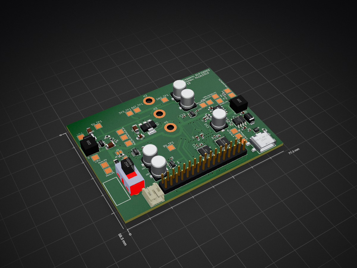
EEE3088F MM Power Project is an open-source printed circuit board by KLPJOA002, from the KLPJOA002/EEE3088F_PCP_Power_Project repository on GitHub. It is a 2-layer board of 77.3 × 58.5 mm with 88 parts on 71 nets, routed with 734 tracks and 109 vias.
It is built around the DRV8833PWP, MT3608 and TPS5430DDAR, with the AMS1117-3.3, HUSB237-AA001-DN06R and SS-12D06-G050 among its other parts. Its parts include 25 capacitors, 17 resistors, 13 ICs, 2 diodes and 2 connectors.


This repository contains the design files, documentation, and supporting material for the Micromouse Power Subsystem designed as part of the EEE3088F course at the University of Cape Town. The subsystem was built to meet a strict set of functional and mechanical requirements under tight budget constraints.
Micromouse is a global robotics competition in which small autonomous robots solve mazes. The UCT EEE3088F course replicates this challenge by requiring students to develop individual subsystems that together build a complete micromouse. This repository documents the design and implementation of the Power Subsystem, which is responsible for:
/KiCad_Files./Gerbers, /PnP, and /BOM to JLCPCB./Screenshots for evidence of successful upload and configuration.All files have been validated and successfully uploaded to JLCPCB. Screenshots showing the:
/Screenshots.Alex Hillman HLLALE010
Joab Kloppers KLPJOA002
Both team members contributed distinct sections of the PCB design and documentation, as per the individual assessment requirements of the course.
GitHub: EEE3088F_PCP_Power_Project
Contributions are limited to the Power Subsystem. Design files and reports are subject to UCT's academic integrity policies.
This project is licensed for academic purposes only.
| Qty | Value | Footprint | References |
|---|---|---|---|
| 8 | TestPoint | TestPoint:TestPoint_Pad_2.5x2.5mm | CHRG_SelectR1_TP1, CHRG_SelectR1_TP2, CHRG_SelectR2_TP1, CHRG_SelectR2_TP2, CHRG_VinR_TP1, CHRG_VinR_TP2, Shunt_TP1, Shunt_TP2 |
| 4 | 220uF | Capacitor_SMD:C_Elec_6.3x7.7 | C20, C21, C30, C31 |
| 3 | 1uF | Capacitor_SMD:C_0402_1005Metric_Pad0.74x0.62mm_HandSolder | C13, C28, C33 |
| 3 | 2.2k | Resistor_SMD:R_0402_1005Metric_Pad0.72x0.64mm_HandSolder | R10, R11, R14 |
| 3 | 3.3k | Resistor_SMD:R_0402_1005Metric_Pad0.72x0.64mm_HandSolder | R9, R16, R17 |
| 3 | MountingHole | MountingHole:MountingHole_3.2mm_M3_DIN965_Pad | H1, H2, H3 |
| 3 | ~ | TestPoint:TestPoint_Pad_2.5x2.5mm | 5V_R1_TP1, L_TP_1, L_TP_2 |
| 2 | 0R | Resistor_SMD:R_0603_1608Metric_Pad0.98x0.95mm_HandSolder | R5, R6 |
| 2 | 100nF | Capacitor_SMD:C_0402_1005Metric_Pad0.74x0.62mm_HandSolder | C23, C32 |
| 2 | 10nF | Capacitor_SMD:C_0402_1005Metric_Pad0.74x0.62mm_HandSolder | C12, C16 |
| 2 | 10u | Capacitor_SMD:C_0603_1608Metric_Pad1.08x0.95mm_HandSolder | C7, C9 |
| 2 | 10uF | Capacitor_SMD:C_0603_1608Metric_Pad1.08x0.95mm_HandSolder | C14, C17 |
| 2 | 2.2uF | Capacitor_SMD:C_0402_1005Metric_Pad0.74x0.62mm_HandSolder | C11, C15 |
| 2 | 22u | Inductor_SMD:L_Sunlord_SWPA6045S | L2, L3 |
| 2 | 22u | Capacitor_SMD:C_1206_3216Metric_Pad1.33x1.80mm_HandSolder | C1, C2 |
| 2 | AP22814AW5-7 | JLCPCB:SOT-25_L3.0-W1.6-P0.95-LS2.8-BL | U12, U14 |
| 2 | DRV8833PWP | JLCPCB:TSSOP-16_L5.0-W4.4-P0.65-LS6.4-BL-EP | U8, U10 |
| 2 | SS34_C8678 | JLCPCB:SMA_L4.3-W2.6-LS5.2-RD | D1, D2 |
| 1 | 100m | Resistor_SMD:R_1206_3216Metric_Pad1.30x1.75mm_HandSolder | R1 |
| 1 | 100p | Capacitor_SMD:C_0603_1608Metric_Pad1.08x0.95mm_HandSolder | C3 |
| 1 | 10k | Resistor_SMD:R_0402_1005Metric_Pad0.72x0.64mm_HandSolder | R13 |
| 1 | 10p | Capacitor_SMD:C_0603_1608Metric_Pad1.08x0.95mm_HandSolder | C8 |
| 1 | 1k | Resistor_SMD:R_0402_1005Metric_Pad0.72x0.64mm_HandSolder | R12 |
| 1 | 2.2R | Resistor_SMD:R_0603_1608Metric_Pad0.98x0.95mm_HandSolder | R8 |
| 1 | 220k | Resistor_SMD:R_0603_1608Metric_Pad0.98x0.95mm_HandSolder | R2 |
| 1 | 220u | Capacitor_SMD:C_Elec_6.3x7.7 | C10 |
| 1 | 22k | Resistor_SMD:R_0603_1608Metric_Pad0.98x0.95mm_HandSolder | R3 |
| 1 | 33k | Resistor_SMD:R_0402_1005Metric_Pad0.72x0.64mm_HandSolder | R4 |
| 1 | 3V3 TP | TestPoint:TestPoint_Pad_2.5x2.5mm | 3V3_TP1 |
| 1 | 4.7R | Resistor_SMD:R_0603_1608Metric_Pad0.98x0.95mm_HandSolder | R7 |
| 1 | 4.7u | Capacitor_SMD:C_0603_1608Metric_Pad1.08x0.95mm_HandSolder | C6 |
| 1 | 5V FB TP | TestPoint:TestPoint_Pad_2.5x2.5mm | 5V_FB_TP1 |
| 1 | 5V R2 TP | TestPoint:TestPoint_Pad_2.5x2.5mm | 5V_R2_TP1 |
| 1 | 5V TP | TestPoint:TestPoint_Pad_2.5x2.5mm | 5V_TP1 |
| 1 | 75k | Resistor_SMD:R_0603_1608Metric_Pad0.98x0.95mm_HandSolder | R15 |
| 1 | 9-5V R1 TP | TestPoint:TestPoint_Pad_2.5x2.5mm | 9-5V_R1_TP1 |
| 1 | 9-5V R2 TP | TestPoint:TestPoint_Pad_2.5x2.5mm | 9-5V_R2_TP1 |
| 1 | 9-5V VSense TP | TestPoint:TestPoint_Pad_2.5x2.5mm | 9-5V_VSense_TP1 |
| 1 | 9V TP | TestPoint:TestPoint_Pad_2.5x2.5mm | 9V_TP1 |
| 1 | AMS1117-3.3 | Package_TO_SOT_SMD:SOT-223-3_TabPin2 | U3 |
| 1 | BAT TP | TestPoint:TestPoint_Pad_2.5x2.5mm | BAT_TP1 |
| 1 | CA45-A-10V-22UF-K | JLCPCB:CASE-A_3216 | C5 |
| 1 | Conn_01x02 | Connector_JST:JST_PH_S2B-PH-K_1x02_P2.00mm_Horizontal | J1 |
| 1 | Conn_02x16_Odd_Even | Connector_PinHeader_2.54mm:PinHeader_2x16_P2.54mm_Vertical | J2 |
| 1 | GND TP | TestPoint:TestPoint_Pad_2.5x2.5mm | GND_TP1 |
| 1 | HUSB237-AA001-DN06R | JLCPCB:TDFN-6_L2.0-W2.0-P0.65-TL-EP | U9 |
| 1 | INA219AIDCNR | JLCPCB:SOT-23-8_L3.0-W1.7-P0.65-LS2.8-BR | U2 |
| 1 | MT3608 | Package_TO_SOT_SMD:SOT-23-6 | U1 |
| 1 | Possible Filter Cap | Jumper:SolderJumper-2_P1.3mm_Open_Pad1.0x1.5mm | JP3 |
| 1 | Possible Filter Res1 | Jumper:SolderJumper-2_P1.3mm_Open_Pad1.0x1.5mm | JP1 |
| 1 | Possible Filter Res2 | Jumper:SolderJumper-2_P1.3mm_Open_Pad1.0x1.5mm | JP2 |
| 1 | SS-12D06-G050 | JLCPCB:SW-TH_3P-P4.70_SS-12D06-G050 | U11 |
| 1 | TAJA106K016RNJ | JLCPCB:CAP-SMD_L3.2-W1.6-RD-C7171 | C4 |
| 1 | TP4056 | JLCPCB:ESOP-8_L4.9-W3.9-P1.27-LS6.0-BL-EP | U5 |
| 1 | TPS5430DDAR | JLCPCB:ESOP-8_L4.9-W3.9-P1.27-LS6.0-TL-EP | U4 |
| 1 | TS5A3159DCKR | JLCPCB:SC-70-6_L2.0-W1.3-P0.65-LS2.1-BL-1 | U6 |
| 1 | TYPE-C_16P_QTGM027 | JLCPCB:USB-C-SMD_TYPE-C-16P-QTGM027 | U7 |
KLPJOA002/EEE3088F_PCP_Power_Project
Git hub repo containing pcp and kicad files for EEE3088F 2025 project

May-engineer/EEE3088F-Micromouse-power-module-
repo used to keep track of latest PCB design

badgeteam/konsool-zero
RFID NFC <1GHz radio Konsool expansion board


KushlaVR/models-heart
Можливості: Керування через WIFI з телефона або ПК 5 незалежних каналів (світлодіоди/сервомотори) 1 Н-міст для підключення мотора (піковий струм до 3А) Вмонтована BMS 1S та контроллер заряду Li-Ion акумулятора з…

OpenAVNS/OpenAVNS
Hardware, firmware, and mechanical design
It measures 77.3 × 58.5 mm and has 2 copper layers, 1.6 mm thick.
88 parts, built around the DRV8833PWP, MT3608, TPS5430DDAR and AMS1117-3.3. The full list of its parts is on this page, with links to each part's symbol and footprint where PCBKit's library has them.
From the KLPJOA002/EEE3088F_PCP_Power_Project repository on GitHub, at the commit this page was made from: the board is KiCad Circuit Stuff/EEE3088F_MM_Power_Project/EEE3088F_MM_Power_Project.kicad_pcb and its schematic KiCad Circuit Stuff/Alex Schematics/Alex Schematics.kicad_sch. PCBKit opens the board in the browser, with nothing to install.
Its repository states no licence, so its author keeps all rights: ask KLPJOA002 before reusing the design.