2 layers84.7 × 80.8 mm

 JudasLilith/ESPCord
a power controller powered with the ESP32.
ESPCord is an open-source printed circuit board by JudasLilith, from the JudasLilith/ESPCord repository on GitHub, published under the GPL-3.0 licence. It is a 2-layer board of 17.4 × 29.9 mm with 8 parts on 43 nets, routed with 90 tracks and 4 vias.
It is built around the ESP32-C3 and SRD-03VDC-SL-C. Its parts include 2 capacitors, 2 resistors, 2 ICs, 1 connector and 1 switch. It belongs with the ESP32 and RISC-V boards of this library.


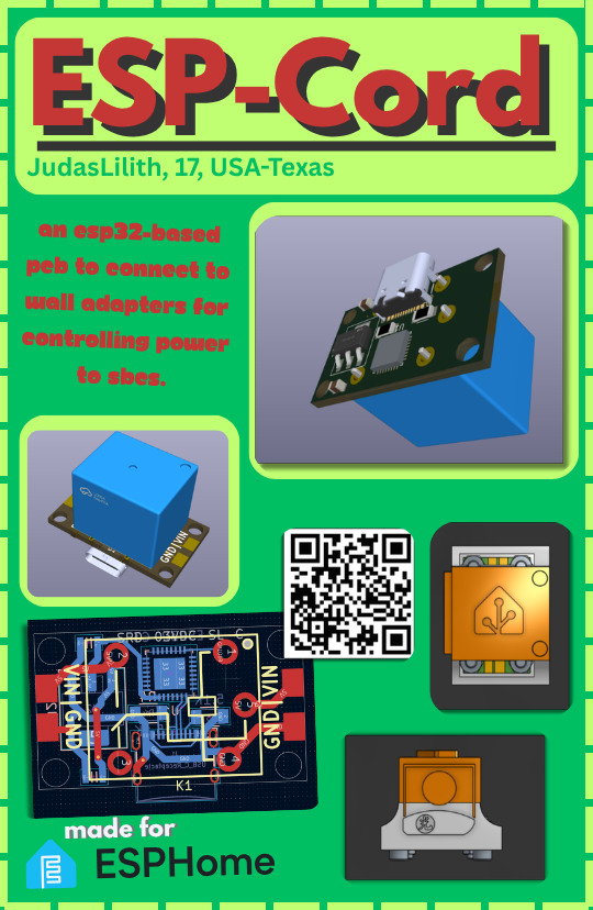
I normally use a small Raspberry Pi Zero in order for me to control my Octoprint setup, but due to the board being connected constantly it cannot shut down with the normal octoprint UI. This is when I thought that I should have a method of controlling the power going to the Setup, so that it can properly reboot every time I manipulate its power source by being connected to Home Assistant.
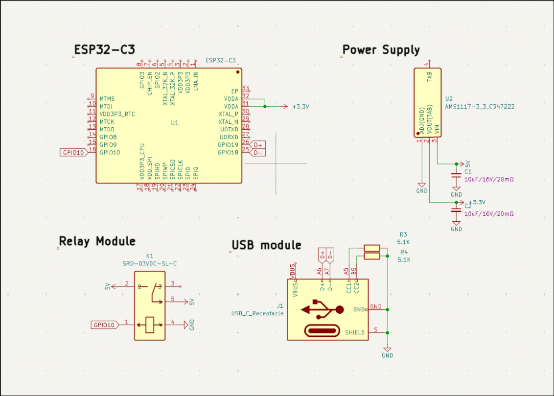
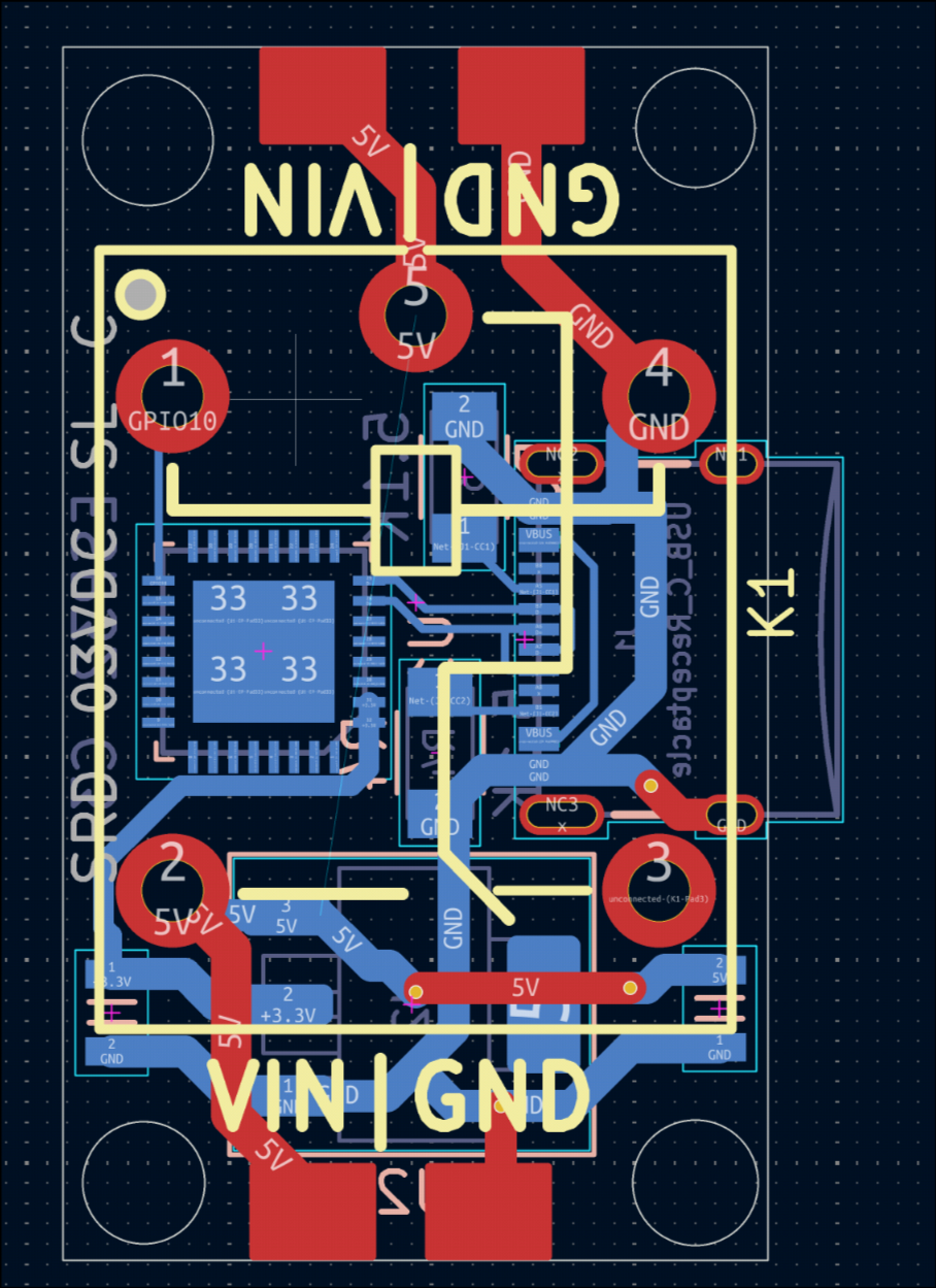
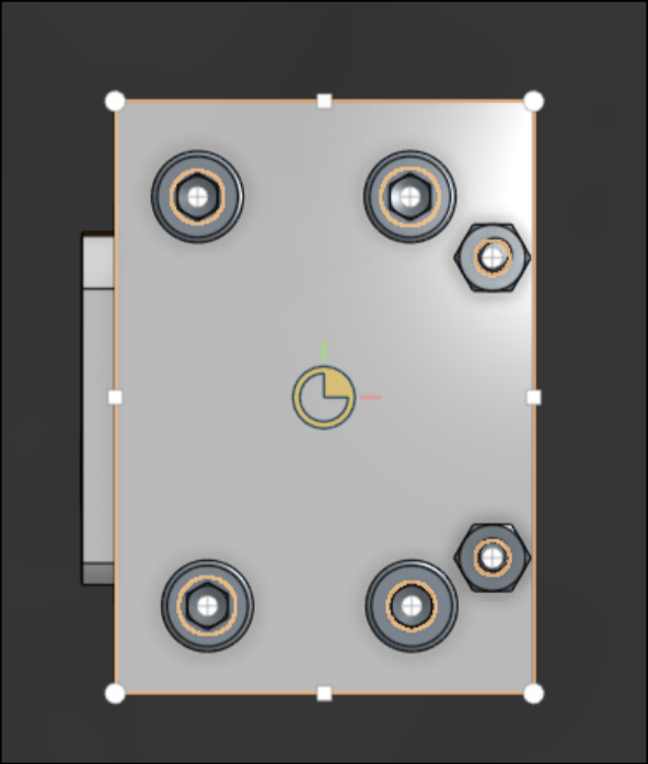
WARNING! The USB and the actual power supply coming from the wires are synonymous, so I do not recommend connecting the Power pins and the USB to flash the program at the same time.
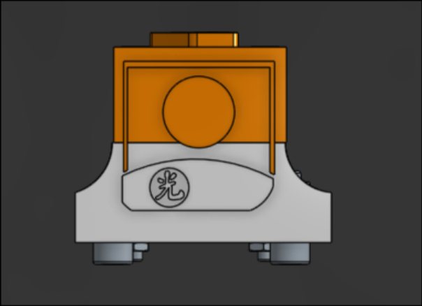
The step files for the cover are in hardware/STEP. For each of the PCB's models, it's inside /hardware/ESPCord/JLCImport.3dshapes/.
Go to OnShape for the source files: Link to Document
For the Detailed version with comments, look at the BOM.csv
| Reference | Qty | Value | Price | Footprint |
| C1,C2 | 2 | 10uF_0805_16V_lowESR | 0.091 | PCM_4ms_Capacitor:C_0805 |
| J1 | 1 | USB_C_Receptacle | 0.05 | PCM_SparkFun-Connector:USB-C_16 |
| K1 | 1 | SRD-03VDC-SL-C | 0.41 | JLCImport:SRD-03VDC-SL-C |
| R3,R4 | 2 | 5.1K | 0.02 | PCM_fab:R_1206 |
| U1 | 1 | ESP32-C3 | 1.83 | PCM_fab:QFN-32_EP_5x5_Pitch0.5mm |
| U2 | 1 | AMS1117-3_3_C347222 | 0.01 | PCM_Package_TO_SOT_SMD_AKL:SOT-223-5 |
| 0 | ||||
| 4 | M3 Bolts 10mm | 19.99 | N/A | |
| 2 | M2 Bolts 25mm | 0 | N/A | |
| 4 | M3 Nuts | 0 | N/A | |
| 2 | m2 Nuts | 0 | N/A | |
| Total: | 22.351 |
Total: 22.351 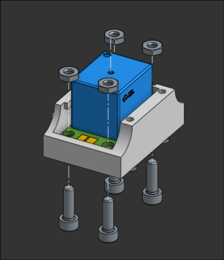
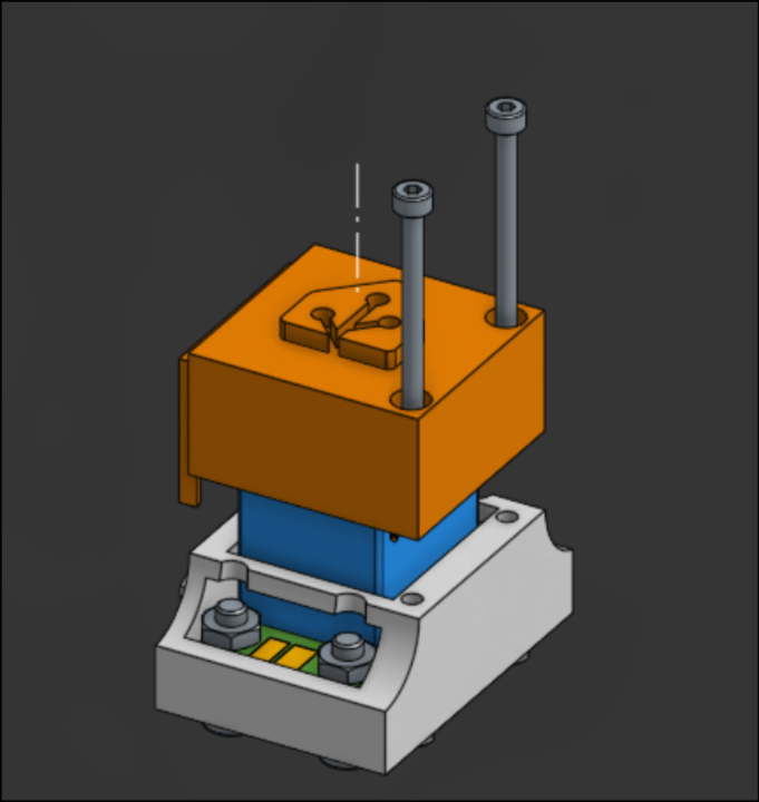
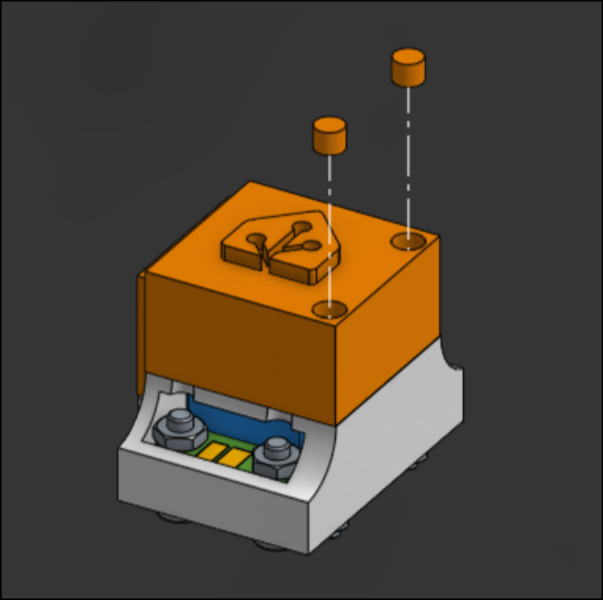
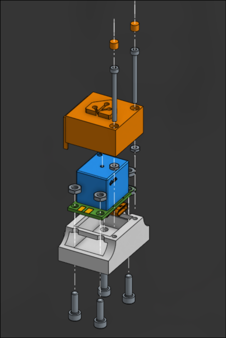
Time to actually connect the relay with the power cables now.
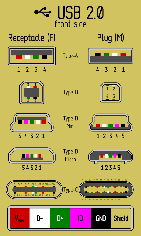
Now all you need to do is:
Great job following along! now you must flash the ESP with ESPHome. (You can find more information at: https://esphome.io/guides/getting_started_hassio/)
I tried to make a simple configuration file in /firmware, but it's not tested yet so take it with a grain of salt please :3
| Qty | Value | Footprint | References |
|---|---|---|---|
| 2 | 10uF_0805_16V_lowESR | PCM_4ms_Capacitor:C_0805 | C1, C2 |
| 2 | 5.1K | PCM_fab:R_1206 | R3, R4 |
| 1 | AMS1117-3_3_C347222 | PCM_Package_TO_SOT_SMD_AKL:SOT-223-5 | U2 |
| 1 | ESP32-C3 | PCM_fab:QFN-32_EP_5x5_Pitch0.5mm | U1 |
| 1 | SRD-03VDC-SL-C | JLCImport:SRD-03VDC-SL-C | K1 |
| 1 | USB_C_Receptacle | PCM_SparkFun-Connector:USB-C_16 | J1 |


mitchins/esp-hvac-controller
A simple relay based two zone low voltage AC damper controller. May also control other loads.


G-Pereira/greenmobi-bms
A VESC compatible battery management system

OpenDrone-hw/OpenAIO
Open-source AIO for 2-6S toothpick quads: flight controller, 4-in-1 AM32 ESC and ExpressLRS receiver, 25.5x25.5 mm.


It measures 17.4 × 29.9 mm and has 2 copper layers, 1.6 mm thick.
8 parts, built around the ESP32-C3 and SRD-03VDC-SL-C. The full list of its parts is on this page, with links to each part's symbol and footprint where PCBKit's library has them.
From the JudasLilith/ESPCord repository on GitHub, at the commit this page was made from: the board is hardware/ESPCord/ESPCord.kicad_pcb and its schematic hardware/ESPCord/ESPCord.kicad_sch. PCBKit opens the board in the browser, with nothing to install.
Its repository publishes it under the GPL-3.0 licence: you may reuse it on that licence's terms (keep the author's notice, and for a copyleft licence share your changes alike).