2 layers30.5 × 68.6 mm

 Jotrorox/minicontrol
RP2354A + 868 MHz LoRa (Ai-Thinker Ra-01SH) USB-C controller board, designed in KiCad 10.
Minicontrol is an open-source printed circuit board by Jotrorox, from the Jotrorox/minicontrol repository on GitHub, published under the BSD-2-Clause licence. It is a 4-layer board of 50 × 36 mm with 66 parts on 66 nets, routed with 1,400 tracks and 140 vias.
It is built around the RP2354A, RA-01SH and MMC5603NJ, with the AP2112K-3.3TRG1, LSM6DSV16XTR and USBLC6-2SC6 among its other parts. Its parts include 25 capacitors, 16 resistors, 6 ICs, 5 connectors and 2 switches. It belongs with the RP2350 boards of this library.


RP2354A + 868 MHz LoRa (Ai-Thinker Ra-01SH) USB-C controller board, designed in KiCad 10.
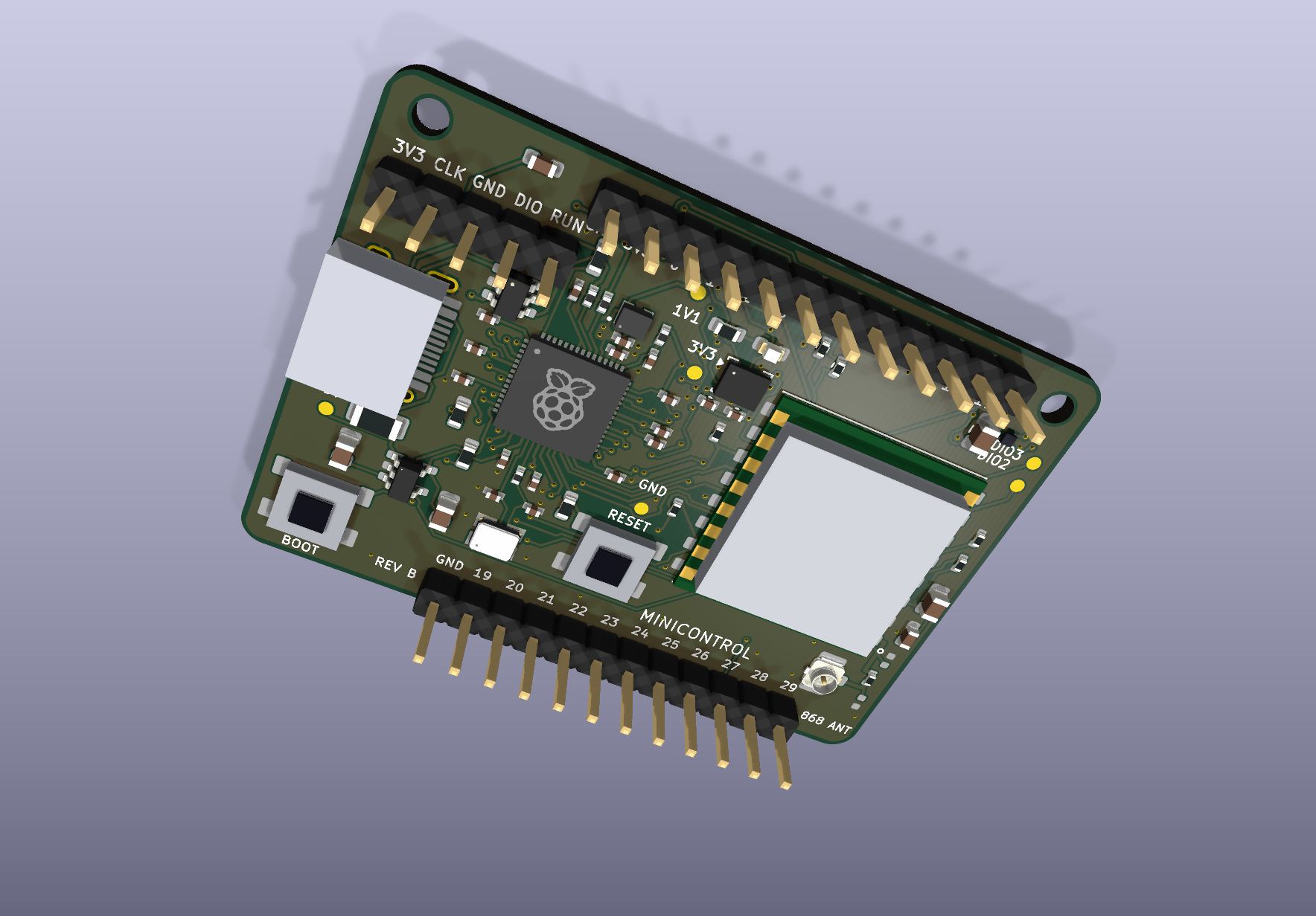
Status: engineering prototype. ERC/DRC are clean, but the hardware has not been built or tested. USB, RF performance, thermals and assembly rotation still need verification.
| Path | Contents |
|---|---|
minicontrol.kicad_pro / _sch / _pcb | KiCad project, schematic and board |
minicontrol.kicad_sym, minicontrol.pretty/ | Project-local symbols and footprints |
3dmodels/ | 3D models (referenced via ${KIPRJMOD}) |
fabrication/ | Gerbers, JLCPCB BOM/CPL, full BOM, schematic PDF, ERC/DRC reports, renders |
firmware/minicontrol_pins.h | Pin map for Pico SDK firmware |
Open minicontrol.kicad_pro in KiCad 10 — all libraries are project-local, so no extra setup is needed.
4 layers, 1.6 mm FR4, 1 oz outer / 0.5 oz inner copper, JLC04161H-7628 stackup, ENIG finish (required for the MMC5603NJ 0.4 mm ball pitch), tented vias.
| Layer | Use |
|---|---|
| F.Cu | Components, signals, GND |
| In1.Cu | Solid GND reference |
| In2.Cu | 3.3 V, local 1.1 V |
| B.Cu | Signals, GND |
Minimum trace/clearance is 0.127 mm (5 mil). The RF feed is a ~50 Ω grounded coplanar line (0.32 mm, 0.15 mm gap) — confirm with the fabricator.
Upload fabrication/minicontrol-Gerbers.zip, JLCPCB-BOM.csv and JLCPCB-CPL.csv.
In the assembly preview, check orientation of U1 pin 1, the radio, USB-C, D1,
L1 (dot toward the 1.1 V output), U5 pin 1 and U6 ball A1.
C22/C23 are DNP and R16 = 0 Ω (RF tuning options).
| Function | GPIO |
|---|---|
| LoRa SPI1 NSS / MISO / SCK / MOSI | 8 / 9 / 10 / 11 |
| LoRa RESET / BUSY / DIO1 | 12 / 13 / 14 |
| LoRa TXEN / RXEN (both low at idle) | 15 / 18 |
| I²C0 SDA / SCL (4.7 kΩ pull-ups) | 0 / 1 |
| IMU INT1 / INT2 | 2 / 3 |
| Status LED (active high) | 25 |
Headers
Test points: TP1 GND, TP2 +3V3, TP3 +1V1, TP4 fused +5V, TP5 DIO2, TP6 DIO3.
WHO_AM_I (0x0F) = 0x70, magnetometer Product ID (0x39) = 0x10.Copyright (c) 2026 Johannes Müller (jotrorox.com).
Original work is licensed under the BSD 2-Clause License. Raspberry Pi-derived material retains its MIT notice in LICENSE-Raspberry-Pi.txt. Third-party footprints and 3D models retain their respective licenses.
| Qty | Value | Footprint | References |
|---|---|---|---|
| 1 | +1V1 | minicontrol:TP3_TestPoint_Pad_D1.0mm | TP3 |
| 1 | +3V3 | minicontrol:TP2_TestPoint_Pad_D1.0mm | TP2 |
| 1 | +5V_USB | minicontrol:TP4_TestPoint_Pad_D1.0mm | TP4 |
| 1 | 0R | minicontrol:R16_R_0402_1005Metric | R16 |
| 1 | 100k | minicontrol:R14_R_0402_1005Metric | R14 |
| 1 | 100k | minicontrol:R13_R_0402_1005Metric | R13 |
| 1 | 100n | minicontrol:C10_generic_capc1005x50 | C10 |
| 1 | 100n | minicontrol:C13_generic_capc1005x50 | C13 |
| 1 | 100n | minicontrol:C21_C_0603_1608Metric | C21 |
| 1 | 100n | minicontrol:C8_generic_capc1005x50 | C8 |
| 1 | 100n | minicontrol:C18_generic_capc1005x50 | C18 |
| 1 | 100n | minicontrol:C14_generic_capc1005x50 | C14 |
| 1 | 100n | minicontrol:C20_C_0603_1608Metric | C20 |
| 1 | 100n | minicontrol:C11_generic_capc1005x50 | C11 |
| 1 | 100n | minicontrol:C25_C_0402_1005Metric | C25 |
| 1 | 100n | minicontrol:C24_C_0402_1005Metric | C24 |
| 1 | 100n | minicontrol:C15_generic_capc1005x50 | C15 |
| 1 | 100n | minicontrol:C16_generic_capc1005x50 | C16 |
| 1 | 100n | minicontrol:C17_generic_capc1005x50 | C17 |
| 1 | 100n | minicontrol:C12_generic_capc1005x50 | C12 |
| 1 | 10k | minicontrol:R15_R_0402_1005Metric | R15 |
| 1 | 10k | minicontrol:R11_R_0603_1608Metric | R11 |
| 1 | 10k | minicontrol:R12_R_0402_1005Metric | R12 |
| 1 | 10u | minicontrol:C26_C_0805_2012Metric | C26 |
| 1 | 10u | minicontrol:C2_C_0805_2012Metric | C2 |
| 1 | 10u | minicontrol:C1_C_0805_2012Metric | C1 |
| 1 | 10u | minicontrol:C19_C_0805_2012Metric | C19 |
| 1 | 12MHz | minicontrol:X1_ABM8_272_T3 | X1 |
| 1 | 15p | minicontrol:C3_generic_capc1005x50 | C3 |
| 1 | 15p | minicontrol:C4_generic_capc1005x50 | C4 |
| 1 | 1k | minicontrol:R6_R_0603_1608Metric | R6 |
| 1 | 1k | minicontrol:R17_R_0603_1608Metric | R17 |
| 1 | 1k | minicontrol:R2_generic_resc1005x35 | R2 |
| 1 | 27 | minicontrol:R7_generic_resc1005x35 | R7 |
| 1 | 27 | minicontrol:R8_generic_resc1005x35 | R8 |
| 1 | 3.3u | minicontrol:L1_AOTA_B201610S3R3_polarized | L1 |
| 1 | 33 | minicontrol:R3_generic_resc1005x35 | R3 |
| 1 | 350mA PTC | minicontrol:F1_Fuse_1206_3216Metric | F1 |
| 1 | 4.7k | minicontrol:R19_R_0402_1005Metric | R19 |
| 1 | 4.7k | minicontrol:R18_R_0402_1005Metric | R18 |
| 1 | 4.7u | minicontrol:C7_generic_capc1005x50_wide | C7 |
| 1 | 4.7u | minicontrol:C6_generic_capc1005x50_wide | C6 |
| 1 | 4.7u | minicontrol:C9_generic_capc1005x50 | C9 |
| 1 | 5.1k | minicontrol:R9_R_0603_1608Metric | R9 |
| 1 | 5.1k | minicontrol:R10_R_0603_1608Metric | R10 |
| 1 | AP2112K-3.3 | minicontrol:U2_SOT-23-5 | U2 |
| 1 | BOOT | minicontrol:SW1_TS1187_5.1mm | SW1 |
| 1 | DNP / RF tune | minicontrol:C23_C_0402_1005Metric | C23 |
| 1 | DNP / RF tune | minicontrol:C22_C_0402_1005Metric | C22 |
| 1 | GND | minicontrol:TP1_TestPoint_Pad_D1.0mm | TP1 |
| 1 | GPIO A | minicontrol:J2_PinHeader_1x12_P2.54mm_Vertical | J2 |
| 1 | GPIO B | minicontrol:J3_PinHeader_1x12_P2.54mm_Vertical | J3 |
| 1 | LORA_DIO2 | minicontrol:TP5_TestPoint_Pad_D1.0mm | TP5 |
| 1 | LORA_DIO3 | minicontrol:TP6_TestPoint_Pad_D1.0mm | TP6 |
| 1 | LSM6DSV16X | minicontrol:U5_LSM6DSV16X_LGA14 | U5 |
| 1 | M2 | minicontrol:H2_MountingHole_2.2mm_M2 | H2 |
| 1 | M2 | minicontrol:H1_MountingHole_2.2mm_M2 | H1 |
| 1 | MMC5603NJ | minicontrol:U6_MMC5603NJ_WLP4 | U6 |
| 1 | RED | minicontrol:D1_LED_0603_1608Metric | D1 |
| 1 | RESET | minicontrol:SW2_TS1187_5.1mm | SW2 |
| 1 | RP2354A | minicontrol:U1_RP2354A_QFN60_EP_vias | U1 |
| 1 | Ra-01SH / 868 MHz | minicontrol:U4_Ra01SH_16x17mm | U4 |
| 1 | SWD / DEBUG | minicontrol:J4_PinHeader_1x05_P2.54mm_Vertical | J4 |
| 1 | U.FL / ANT | minicontrol:J5_U.FL_Hirose_U.FL-R-SMT-1_Vertical | J5 |
| 1 | USB-C | minicontrol:J1_USB_C_Receptacle_HRO_TYPE-C-31-M-12 | J1 |
| 1 | USBLC6-2SC6 | minicontrol:U3_SOT-23-6 | U3 |

jakeread/knuckles-imu-lsm6-lis2-rp2354a
This is an IMU module that pairs the LSM6DSV16X accelerometer with an LIS2MDL magnetometer, using an RP2354A microcontroller.

Corteil/rp2350-hdmi-hexpansion
RP2350 HDMI hexpansion for the EMF Tildagon badge -- mirrors the badge's display to a monitor over HSTX/DVI

adamhrnciar/hyperion-controller
Open-source controller for 150 g antweight combat robots: RP2354A, 2x DRV8231A, 2-4S, ELRS/CRSF/SBUS/iBUS/PPM input, IMU. KiCad 10, CERN-OHL-S-2.0.

sequoia-hope/ultraroute
PCB autorouting experiments around copperroute: route jobs, leaderboards, board morphing

FujiNetWIFI/fujinet-hardware
Schematics and design files for FujiNet hardware

enkhbold470/kicad-projects
Five KiCad 10 boards (4- and 6-layer): ESP32-S3 industrial gateway, USB-C PD bench supply, RP2040 logic analyzer, FOC motor controller, iCE40 FPGA board.

houseofthe051010/ESP32-Walkie-Talkie-V2
This ESP32 Walkie Talkie is redesigned with a SX1262 radio, a PCB, and a full case redesign.
It measures 50 × 36 mm and has 4 copper layers, 1.6 mm thick.
66 parts, built around the RP2354A, RA-01SH, MMC5603NJ and AP2112K-3.3TRG1. The full list of its parts is on this page, with links to each part's symbol and footprint where PCBKit's library has them.
From the Jotrorox/minicontrol repository on GitHub, at the commit this page was made from: the board is minicontrol.kicad_pcb and its schematic minicontrol.kicad_sch. PCBKit opens the board in the browser, with nothing to install.
Its repository publishes it under the BSD-2-Clause licence: you may reuse it on that licence's terms (keep the author's notice, and for a copyleft licence share your changes alike).