4 layers50 × 73.2 mm
 JoeyStrandnes/AutoTiller
Open source DIY device for steering boats with tillers
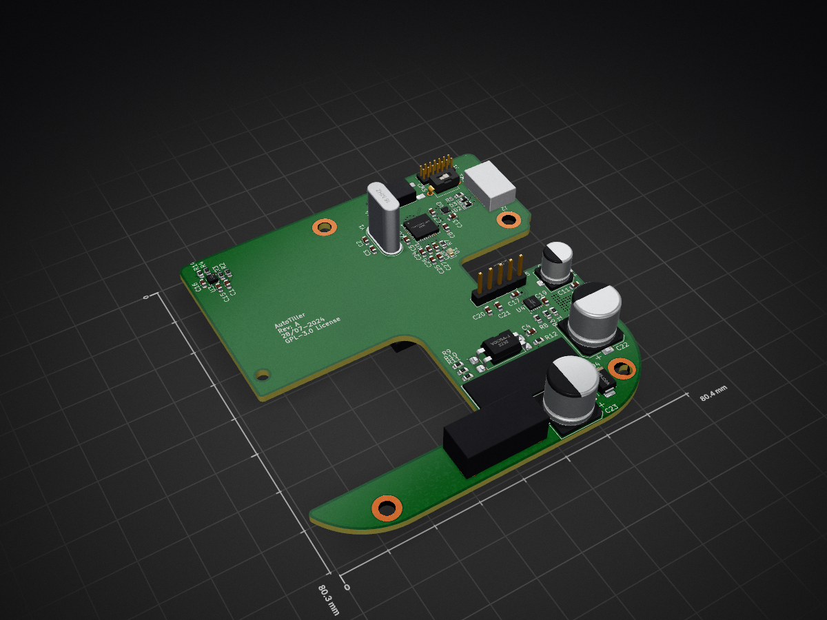
AutoTiller is an open-source printed circuit board by JoeyStrandnes, from the JoeyStrandnes/AutoTiller repository on GitHub, published under the GPL-3.0 licence. It is a 4-layer board of 80.3 × 80.3 mm with 66 parts on 59 nets, routed with 319 tracks and 87 vias.
It is built around the MAX22201ATC, VO615A-4 and TS04-66-95-BK-260-SMT, with the 35TZV330M10X10.5, SP1103C-01UTG and DS04-254-2L-01BK among its other parts. Its parts include 26 capacitors, 14 resistors, 7 ICs, 6 switches and 4 diodes. It belongs with the STM32 boards of this library.


| Qty | Value | Footprint | References |
|---|---|---|---|
| 13 | 100nF | Capacitor_SMD:C_0603_1608Metric | C1, C4, C5, C6, C7, C8, C13, C14, C24, C25, C26, C27, C28 |
| 8 | 1k | Resistor_SMD:R_0603_1608Metric | R1, R6, R7, R9, R10, R11, R12, R13 |
| 7 | 1uF | Capacitor_SMD:C_0603_1608Metric | C10, C11, C15, C17, C19, C20, C21 |
| 5 | 1.69k | Resistor_SMD:R_0603_1608Metric | R2, R3, R4, R8, R14 |
| 4 | MountingHole | MountingHole:MountingHole_3.2mm_M3_DIN965_Pad_TopBottom | H1, H2, H3, H4 |
| 4 | TS04-66-95-BK-260-SMT | AutoTiller:TS04-66-65-BK-160-SMT | SW4, SW5, SW6, SW7 |
| 2 | 20pF | Capacitor_SMD:C_0603_1608Metric | C2, C3 |
| 2 | 330uF | Capacitor_SMD:CP_Elec_10x10.5 | C22, C23 |
| 2 | SP1103C-01UTG | Diode_SMD:D_0603_1608Metric | D2, D3 |
| 1 | 16 MHz | Crystal:Crystal_HC49-U_Vertical | Y1 |
| 1 | 220nF | Capacitor_SMD:C_0603_1608Metric | C16 |
| 1 | 3220-14-0300-00 | Connector_PinHeader_1.27mm:PinHeader_2x07_P1.27mm_Vertical | J1 |
| 1 | 47uF | Capacitor_SMD:CP_Elec_6.3x7.7 | C12 |
| 1 | 5A/50V | AutoTiller:696106003002 | F1 |
| 1 | 910k | Resistor_SMD:R_0603_1608Metric | R5 |
| 1 | BHTGA-A-DW | Connector_PinHeader_2.54mm:PinHeader_1x05_P2.54mm_Vertical | U5 |
| 1 | DS04-254-2L-01BK | AutoTiller:DS04-254-2L-01BK | SW1 |
| 1 | Green | LED_SMD:LED_0603_1608Metric | D1 |
| 1 | IIS2MDCTR | Package_LGA:LGA-12_2x2mm_P0.5mm | U3 |
| 1 | MAX22201 | Package_DFN_QFN:Maxim_TDFN-12-1EP_3x3mm_P0.5mm_EP1.7x2.5mm_ThermalVias | U4 |
| 1 | SMBJ20A | Diode_SMD:D_SMB | D4 |
| 1 | STM32F103T6Ux | Package_DFN_QFN:QFN-36-1EP_6x6mm_P0.5mm_EP4.1x4.1mm | U1 |
| 1 | T4145415031-001 | AutoTiller:T4145415031-001 | J3 |
| 1 | TLV76733DRVx | Package_SON:WSON-6-1EP_2x2mm_P0.65mm_EP1x1.6mm_ThermalVias | U7 |
| 1 | TS04-66-65-BK-160-SMT | AutoTiller:TS04-66-65-BK-160-SMT | SW2 |
| 1 | TUSB320LAI | Package_DFN_QFN:Texas_X2QFN-12_1.6x1.6mm_P0.4mm | U2 |
| 1 | USB_C_Receptacle_USB2.0 | AutoTiller:USB4800-03-A | J2 |
| 1 | VO615A-4 | AutoTiller:VO615A-4X018T | U6 |


zeodotdev/zeo-boards
ESP32-S3 development board with onboard BME280 (temperature, humidity, pressure) and LSM6DS3 (6-axis IMU) sensors. This repo contains the designs, ESP-IDF firmware, and a Python plotter for visualization.

MG-5/buck-converter-automotive
12V-to-5V buck converter for automotive purposes

kocer/direct-sampling-sdr
Direct-sampling SDR transceiver with four phase-coherent channels, and a class-A power amplifier for 1.8 to 54 MHz.

Rivercraft911/R-01_Raster_Laser_Projector
Red, blue and green lasers combine through two dichroc mirrors and bounce off a spinning polygon mirror, which each mirror facet makes one scanline.
It measures 80.3 × 80.3 mm and has 4 copper layers, 1.6 mm thick.
66 parts, built around the MAX22201ATC, VO615A-4, TS04-66-95-BK-260-SMT and 35TZV330M10X10.5. The full list of its parts is on this page, with links to each part's symbol and footprint where PCBKit's library has them.
From the JoeyStrandnes/AutoTiller repository on GitHub, at the commit this page was made from: the board is Electrical/AutoTiller.kicad_pcb and its schematic Electrical/AutoTiller.kicad_sch. PCBKit opens the board in the browser, with nothing to install.
Its repository publishes it under the GPL-3.0 licence: you may reuse it on that licence's terms (keep the author's notice, and for a copyleft licence share your changes alike).