2 layers48 × 50 mm

 JoelNymark/modu-hardware
Here is the pcbs and other hardware for my modular macro pad
4x4-key pcb is an open-source printed circuit board by JoelNymark, from the JoelNymark/modu-hardware repository on GitHub. It is a 2-layer board of 100 × 100 mm with 70 parts on 59 nets, routed with 513 tracks and 35 vias.
It is built around the SN65HVD230D and TPS62162DSG. Its parts include 20 diodes, 17 connectors, 17 switches, 6 capacitors and 3 ICs. It belongs with the keyboards and input boards and the STM32 boards of this library.


KiCad hardware design files, schematics, PCB layouts, and 3D models for the Modu modular macro pad system. Modules connect magnetically via 4-pin pogo headers and communicate over a shared CAN bus.
[!NOTE]
Hub Module (hub-pcb) | 4x4 Keypad Module (4x4-key-pcb) |
|---|---|
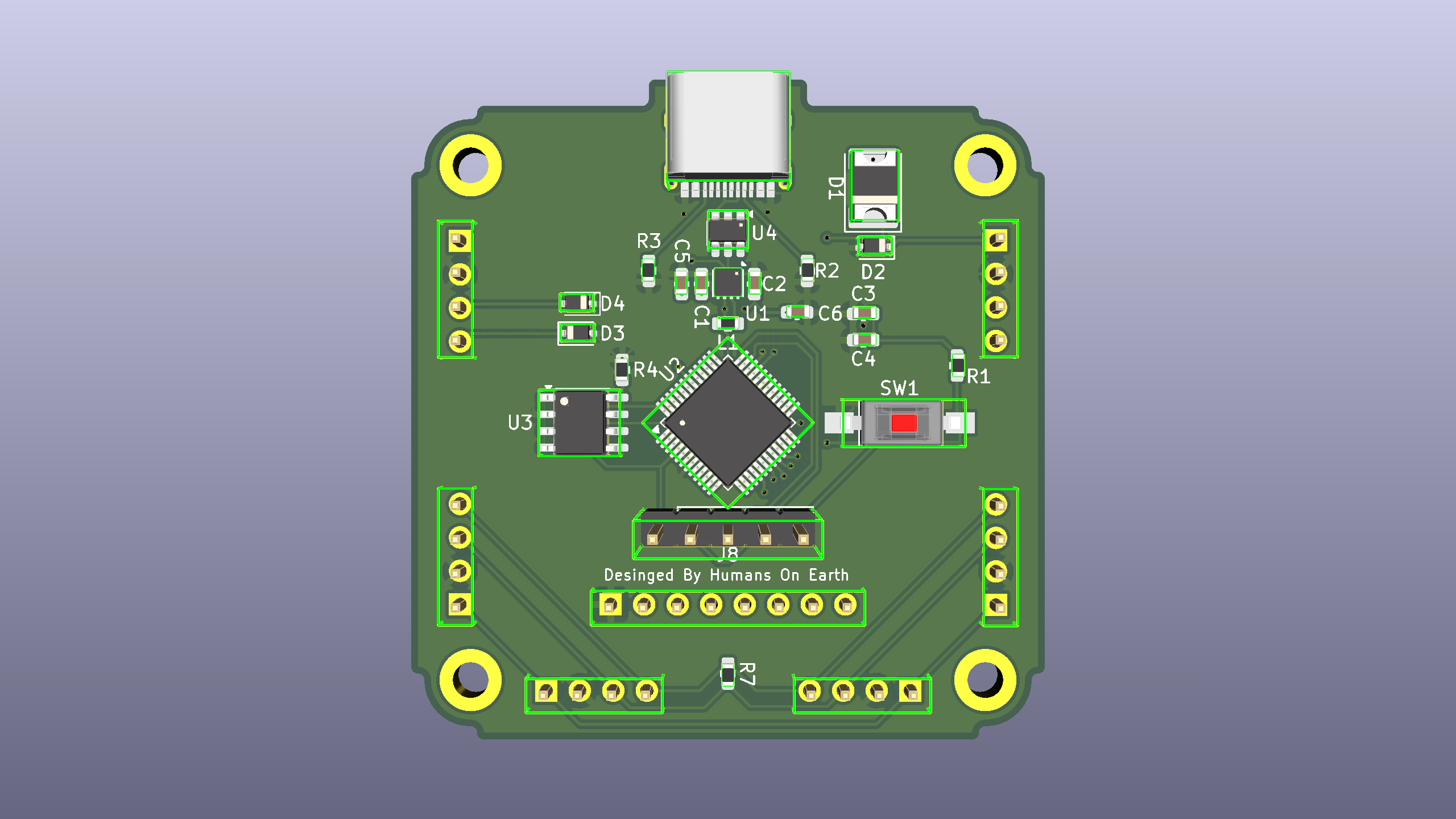 | 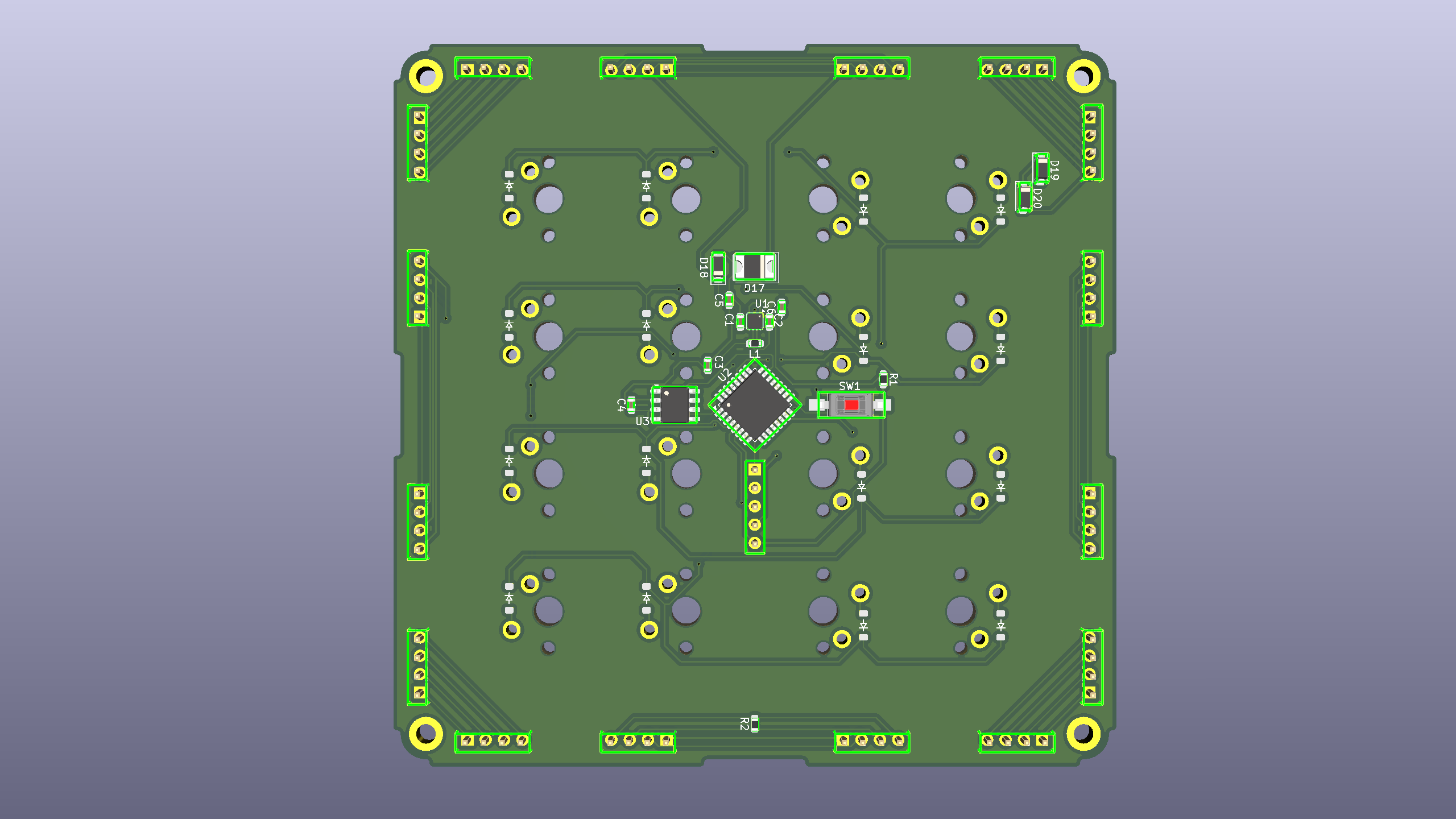 |
| Primary USB-C host controller and power/CAN bus bridge. | Snap-on 16-key mechanical switch matrix module. |
hub-pcb)The master controller module that interfaces with the host PC over USB-C and distributes power and CAN bus communication to connected satellite modules.
U2)U3)U1), USB-C ESD protection (U4), and input reverse/surge protection (D1, D2)J8)4x4-key-pcb)A 16-key modular keypad expansion board that can dock to the Hub or daisy-chain to other modules from any side.
U2)U3)D1–D16)modu-hardware/
├── hub-pcb/ # KiCad project, schematic, PCB, and STEP model for the Hub module
├── 4x4-key-pcb/ # KiCad project, schematic, PCB, and STEP model for the 4x4 Keypad module
├── hub-pcb.png # 3D render of the Hub PCB
└── 4x4-key-pcb.png # 3D render of the 4x4 Keypad PCB| Qty | Value | Footprint | References |
|---|---|---|---|
| 16 | Conn_01x04_Socket | Connector_PinHeader_2.54mm:PinHeader_1x04_P2.54mm_Vertical | J1, J2, J3, J4, J5, J6, J7, J8, J9, J10, J11, J12, J13, J14, J15, J16 |
| 16 | ~ | ScottoKeebs_MX:MX_PCB_1.00u | S1, S2, S3, S4, S5, S6, S7, S8, S9, S10, S11, S12, S13, S14, S15, S16 |
| 16 | ~ | ScottoKeebs_Components:Diode_SOD-123 | D1, D2, D3, D4, D5, D6, D7, D8, D9, D10, D11, D12, D13, D14, D15, D16 |
| 4 | 100nF | Capacitor_SMD:C_0603_1608Metric | C3, C4, C5, C6 |
| 3 | D_TVS | Diode_SMD:D_SOD-123 | D18, D19, D20 |
| 1 | 10kΩ | Resistor_SMD:R_0603_1608Metric | R1 |
| 1 | 10uF | Capacitor_SMD:C_0603_1608Metric | C1 |
| 1 | 2.2uH | Resistor_SMD:R_0603_1608Metric | L1 |
| 1 | 22uF | Capacitor_SMD:C_0603_1608Metric | C2 |
| 1 | Conn_01x05_Pin | Connector_PinHeader_2.54mm:PinHeader_1x05_P2.54mm_Vertical | J17 |
| 1 | D_Schottky | Diode_SMD:D_2114_3652Metric | D17 |
| 1 | R120Ω | Resistor_SMD:R_0603_1608Metric | R2 |
| 1 | SN65HVD230 | Package_SO:SOIC-8_3.9x4.9mm_P1.27mm | U3 |
| 1 | STM32G0B1KBTx | Package_QFP:LQFP-32_7x7mm_P0.8mm | U2 |
| 1 | SW_Push | Button_Switch_SMD:SW_SPST_FSMSM | SW1 |
| 1 | TPS62162DSG | Package_SON:WSON-8-1EP_2x2mm_P0.5mm_EP0.9x1.6mm_ThermalVias | U1 |
The 66 most common of 70 parts.

stanleyondrus/LaserProjectorV2
LaserProjector V2 is a battery-powered, ESP32-based laser XY scanner using stepper motors to deflect the beam. It has auto-homing functionality, and can be controlled wirelessly (Wi-Fi & Bluetooth).

martinribelotta/h730duino
STM32H7 Arduino form factor and software compatible board

doublej380-pixel/OpenDriftRC
Open source drift gyro based on Waveshare ESP32-S3 1.64inch AMOLED touch display development board

Pegoku/Monopoly-Electronic-V2
Gameplay focuses on NFC interaction instead of menus.


It measures 100 × 100 mm and has 2 copper layers, 1.6 mm thick.
70 parts, built around the SN65HVD230D and TPS62162DSG. The full list of its parts is on this page, with links to each part's symbol and footprint where PCBKit's library has them.
From the JoelNymark/modu-hardware repository on GitHub, at the commit this page was made from: the board is 4x4-key-pcb/4x4-key-pcb.kicad_pcb and its schematic 4x4-key-pcb/4x4-key-pcb.kicad_sch. PCBKit opens the board in the browser, with nothing to install.
Its repository states no licence, so its author keeps all rights: ask JoelNymark before reusing the design.