

2 layers28 × 30 mm

 JasonHEngineering/DIY-Robot-Arm-V217
Below illustration of user interface dealing with forward kinematics values:
Stepper with DRV8825 controller board V3 is an open-source printed circuit board by JasonHEngineering, from the JasonHEngineering/DIY-Robot-Arm-V2 repository on GitHub. It is a 2-layer board of 150 × 90 mm with 65 parts on 106 nets, routed with 736 tracks and 87 vias.
It is built around the B140-E3 and ETQP5M470YFC. Its parts include 26 connectors, 16 capacitors, 5 diodes, 4 resistors and 2 ICs. It belongs with the robots and motor control boards and the AVR (ATmega, ATtiny) boards of this library.
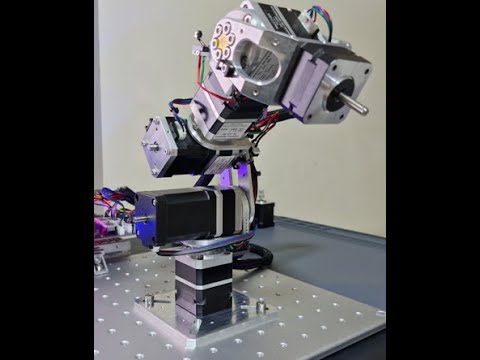
This repository is for archiving a prior 6 DOF robot project that is no longer maintained. I am now working on the next V3 version instead.
| Folder | Contents |
|---|---|
| Adaptor Board | KiCad Project files. Gerber files for PCB. But no SMD assembly because for this variant of adaptor board, I did the soldering myself using both soldering iron and hot air solder. |
| Arduino Nano | Load this file into Arduino Nano 33 BLE/IoT device. This is to be mounted into adaptor board above. |
| CAD files | Step files and 2d drawings. 2d drawings are not fully detailed; mainly the threads and tight tolerances are detailed. |
| Raspberry Pi | Python script and dependencies to be run on raspberry Pi 3/4 |
Machined CNC parts placement in assembly as shown below.
[!NOTE] In such a setup, micro limit switches can only zero the respective axis angles approximately. Next version shall use absolute encoders.
Below illustration of user interface dealing with forward kinematics values:

For more data/info, please refer to this WordPress page.
| Qty | Value | Footprint | References |
|---|---|---|---|
| 6 | 100uF | Capacitor_THT:CP_Radial_D5.0mm_P2.50mm | C11, C12, C13, C14, C15, C16 |
| 6 | Conn_01x03_Female | Connector_JST:JST_PH_B3B-PH-K_1x03_P2.00mm_Vertical | J17, J18, J19, J22, J23, J24 |
| 6 | Conn_01x04_Female | Connector_JST:JST_XH_B4B-XH-A_1x04_P2.50mm_Vertical | J15, J16, J20, J21, J25, J26 |
| 6 | Pololu_Breakout_DRV8825 | Module:Pololu_Breakout-16_15.2x20.3mm | A2, A3, A4, A5, A6, A7 |
| 5 | 0.1uF | Capacitor_SMD:C_0805_2012Metric_Pad1.18x1.45mm_HandSolder | C3, C4, C8, C9, C10 |
| 5 | Conn_01x04_Female | Connector_JST:JST_PH_B4B-PH-K_1x04_P2.00mm_Vertical | J5, J6, J8, J12, J13 |
| 4 | 470uF | Capacitor_THT:CP_Radial_D10.0mm_P5.00mm | C1, C2, C6, C7 |
| 4 | Conn_01x02_Female | Connector_JST:JST_PH_B2B-PH-K_1x02_P2.00mm_Vertical | J2, J3, J4, J7 |
| 2 | 100 Ohm | Resistor_SMD:R_0805_2012Metric_Pad1.20x1.40mm_HandSolder | R2, R3 |
| 2 | B140-E3 | Diode_SMD:D_SMA | D2, D3 |
| 2 | Blue_LED_3V | LED_SMD:LED_0805_2012Metric_Pad1.15x1.40mm_HandSolder | D4, D5 |
| 2 | Conn_02x03_Odd_Even | Connector_PinHeader_2.54mm:PinHeader_2x03_P2.54mm_Vertical | J9, J10 |
| 2 | ETQP5M470YFC | Panasonic_SMD_Inductor:IND_ETQP5M470YFC | L1, L2 |
| 2 | TS2596CM550 RNG | Package_TO_SOT_SMD:TO-263-5_TabPin3 | U1, U2 |
| 1 | 1000uF | Capacitor_THT:CP_Radial_D10.0mm_P5.00mm | C5 |
| 1 | 500 Ohm | Resistor_SMD:R_0805_2012Metric_Pad1.20x1.40mm_HandSolder | R1 |
| 1 | 9-12 V | Barrel Jack:NINIGI_DC-005 | J1 |
| 1 | Arduino_Nano_33_IoT | Module:Arduino_Nano | A1 |
| 1 | Conn_01x02_Female | Connector_JST:JST_XH_B2B-XH-A_1x02_P2.50mm_Vertical | J11 |
| 1 | Conn_02x20_Odd_Even | Connector_PinHeader_2.54mm:PinHeader_2x20_P2.54mm_Vertical | J14 |
| 1 | Fuse | Littelfuse_RGEF_resettable_fuse:FUSRB510W81L1358T310H1980 | F1 |
| 1 | LOGO | my_logo:my_logo_10mm | G*** |
| 1 | Q_NPN_BCE | Package_TO_SOT_THT:TO-220-3_Vertical | Q1 |
| 1 | R | Resistor_SMD:R_0805_2012Metric_Pad1.20x1.40mm_HandSolder | R4 |
| 1 | Red_LED_2V | LED_SMD:LED_0805_2012Metric_Pad1.15x1.40mm_HandSolder | D1 |


clytle374/Open-T12-Soldering-Station
This is a clone of the cheap T12 soldering stations, attempting to eliminate the shortfalls of the cheap designs.

GonzaCerv/noah-hardware
This repo contains all the hardware description for the Noah project. Here lies 3D models, electronics PCB and Firmware software of the robot.

CosmicPi/CosmicPiV1.7PCB
PCB for Version 1.7 of the Cosmic Pi Hardware. Incremental changes from V1.6. This design is licensed under the CERN OHL V1.2


djtersteegc/fujinet-appleii-hardware
Hardware variants for the Apple II FujiNet platform (FujiApple)
It measures 150 × 90 mm and has 2 copper layers, 1.67 mm thick.
65 parts, built around the B140-E3 and ETQP5M470YFC. The full list of its parts is on this page, with links to each part's symbol and footprint where PCBKit's library has them.
From the JasonHEngineering/DIY-Robot-Arm-V2 repository on GitHub, at the commit this page was made from: the board is Adaptor Board (schema, gerbers, kicad project folder)/stepper_with_DRV8825_controller_board_V3/stepper_with_DRV8825_controller_board_V3.kicad_pcb and its schematic Adaptor Board (schema, gerbers, kicad project folder)/stepper_with_DRV8825_controller_board_V3/stepper_with_DRV8825_controller_board_V3.kicad_sch. PCBKit opens the board in the browser, with nothing to install.
Its repository states no licence, so its author keeps all rights: ask JasonHEngineering before reusing the design.