
2 layers67.1 × 25.4 mm
Danger Monitor System Receiver
JanClyde05/Danger-Monitor-System
ESP32 Based GPS Tracker System using IMU for Motion Tracking Analysis and NRF24L01 for fast rescue information access
3 parts3
 JanClyde05/Danger-Monitor-System3
ESP32 Based GPS Tracker System using IMU for Motion Tracking Analysis and NRF24L01 for fast rescue information access
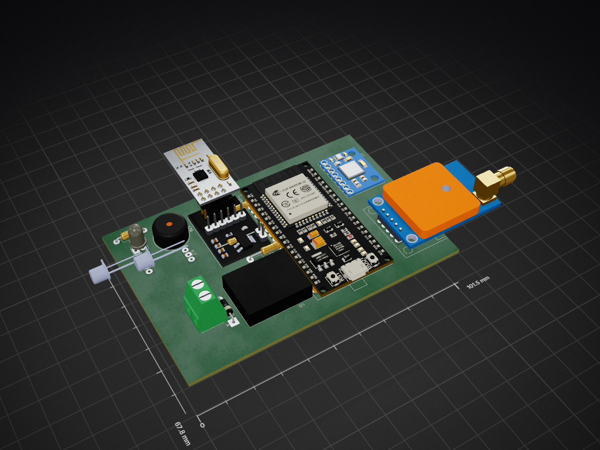
Danger Monitor System Transmitter is an open-source printed circuit board by JanClyde05, from the JanClyde05/Danger-Monitor-System repository on GitHub. It is a 2-layer board of 101.5 × 67.8 mm with 17 parts on 50 nets, routed with 126 tracks and 0 vias.
It is built around the 2N2222A. Its parts include 5 ICs, 2 diodes, 1 resistor and 1 connector.
The system is a wearable/embedded safety monitor that detects:
It then:
FA,TOKEN,LAT,LNG NRF packet to notify the receiverBOOT → INIT HARDWARE → CALIBRATION → RUN LOOP
↓
READ SENSORS (IMU + GPS)
↓
APPLY SIM OVERRIDE (if drill mode)
↓
UPDATE FALL-IMPACT-STILLNESS FSM
↓
CHECK SKID / DIRECT IMPACT DETECTORS
↓
CHECK ENVIRONMENTAL ANALYSIS (every 1 s)
↓
SEND NRF ALERT + SOS (if triggered)
↓
POLL PHYSICAL BUTTON (two-state toggle)
↓
UPDATE WEB UI + BURST TEST (non-blocking)
↓
REPEAT[FS_IDLE]
↓ A_m < 0.40 g
[FS_FREEFALL]
↓ sustained ≥ 100 ms
[FS_WAIT_IMPACT]
↓ A_m > 3.00 g within 500 ms
[FS_STILLNESS]
↓ σ(A_m) < 0.15 g over 2 s
[FS_CONFIRMED → ALERT]All stages must pass — eliminates false positives from jumping, device drops, or sleeping.
SKID / SLIDE:
  ay > 2.0 g  AND  gx > 330 °/s  sustained ≥ 200 ms
  → Ref: motorcycle crash paper, 96% accuracy

DIRECT IMPACT:
  A_m spike > 4.50 g  (no freefall precondition)
  5 s debounce between events
→ Ref: construction-site LF falls 4–9 g (Sensors 2022)[ACCIDENT DETECTED]
↓
[NRF PAYLOAD: "TOKEN,LAT,LNG"]
↓
[RECEIVER HID TRIGGERS URL]
↓
[NETLIFY PROFILE PAGE OPENS]
↓
[MEDICAL INFO + QR CODE DISPLAYED]
↓
[RESPONDER SCANS QR → tel: DIALS CONTACT]
↓ (optional)
[RESPONDER CONFIRMS ACCIDENT → DATABASE ENTRY][ALERT ACTIVE]
↓ (user presses physical button OR web False Alarm button)
[stopSOSAlert() — LED/buzzer off]
↓
[nrfSendFalseAlarm(): "FA,TOKEN,LAT,LNG"]
↓
[RECEIVER HID TRIGGERS FALSE ALARM URL]
↓
[NETLIFY: green "USER IS SAFE" page]
↓
[RESCUER INFORMED — NO RESPONSE NEEDED]setup():
Start Serial (115200)
Start GPS UART1 (9600 baud, RX=16, TX=17)
Initialize I2C (Wire.begin)
Wake MPU-6050 (write 0x00 to PWR_MGMT_1)
Calibrate MPU (3 seconds, 200 samples)
Record gpsSearchStart timestamp
Start WiFi AP (SSID: "GPS Danger Monitor", open, IP: 192.168.4.1)
Initialize NRF24 (CE=2, CSN=15, PA_HIGH, 32-byte payload)
Register all WebServer routes
Configure GPIO: LED (4), Buzzer (5), Button (0 INPUT_PULLUP)loop():
Compute delta time dt
server.handleClient()
Poll physical button (50 ms debounce, two-state toggle)
Run NRF burst test step (non-blocking, if pending)
Feed GPS bytes → TinyGPS++, update hasFix / lastLat / lastLng
readMPU() → apply sim override → updateOrientation(dt)
Compute A_m = sqrt(ax²+ay²+az²)
pushEnvSample(A_m, roll, pitch)
Run Fall-Impact-Stillness FSM (if armed)
Run Skid detector (if armed, FSM idle)
Run Direct-Impact detector (if armed, FSM idle, not in skid)
Environmental analysis (every 1 s, if armed, not sim)
Drive SOS pattern (non-blocking)Raw MPU Data → Bias Removal → Physical Units → Orientation EstimationComplementary filter (α = 0.02):
aRoll  = atan2(ay, az) × 57.296°
aPitch = atan2(-ax, √(ay²+az²)) × 57.296°

roll  = (1-α)×(roll  + gx×dt) + α×aRoll
pitch = (1-α)×(pitch + gy×dt) + α×aPitchA_m = sqrt(ax² + ay² + az²)Orientation-independent scalar used by all detection stages.
| State | Meaning |
|---|---|
| FS_IDLE | Normal monitoring |
| FS_FREEFALL | Low-gravity condition detected |
| FS_WAIT_IMPACT | Waiting for impact spike |
| FS_STILLNESS | Verifying post-impact unconscious |
| FS_CONFIRMED | Alert triggered |
FS_IDLE
  IF A_m < 0.40 g → FS_FREEFALL, start timer

FS_FREEFALL
  IF A_m ≥ 0.40 g → back to FS_IDLE (false trigger)
  IF duration ≥ 100 ms → FS_WAIT_IMPACT
    Record fallStartMs, increment fallEventCount

FS_WAIT_IMPACT
  IF A_m > 3.00 g → FS_STILLNESS, reset stillness buffer
  IF timeout > 500 ms → FS_IDLE, increment fallCancelCount

FS_STILLNESS
  Collect samples for 2000 ms
  Compute σ(A_m)
  IF σ < 0.15 g → FS_CONFIRMED
  ELSE          → FS_IDLE (user conscious), increment fallCancelCount

FS_CONFIRMED
  Increment fallConfirmCount
  Log response time (now − fallStartMs)
  IF !simMode → nrfSendCoords(lastLat, lastLng, "Fall confirmed")
  ELSE        → nrfSendTest(99, "SIMFALL")
  startSOSAlert()
→ FS_IDLEActive when: armed == true AND fallState == FS_IDLE
Condition: fabsf(ay) > 2.0 g  AND  fabsf(gx) > 330 °/s

If condition holds:
  Start skid timer on first detection
  If sustained ≥ 200 ms:
    skidCount++
    nrfSendCoords() OR nrfSendTest (sim)
    startSOSAlert()
    inSkid = false (reset)

If condition breaks before 200 ms:
  inSkid = false (cancel)
Reference: motorcycle crash paper, lateral 0.70 g + roll rate criteria, 96% accuracy. (Note: firmware thresholds are set higher — 2.0 g / 330 °/s — for reduced false positives in the specific deployment scenario.)
Active when: armed == true AND fallState == FS_IDLE AND !inSkid
Condition: A_m > 4.50 g  AND  (now − lastImpactAlert) > 5000 ms

  lastImpactAlert = now
  impactCount++
  nrfSendCoords() OR nrfSendTest (sim)
  startSOSAlert()
Reference: Sensors 2022 — low-floor fall studies, 4–9 g impact range.
Runs every 1000 ms using the last bufCount samples from the rolling buffer (max 50).
sMag   = stddev(magBuf)
sRoll  = stddev(rollBuf)
sPitch = stddev(pitchBuf)

groundShock:  sMag ≥ 0.40  AND  sRoll < 10.0  AND  sPitch < 10.0
waveMotion:   sMag ≥ 0.24  AND  (sRoll ≥ 10.0 OR sPitch ≥ 10.0)

IF groundShock → nrfSendCoords("Ground shock")   + startSOSAlert()
IF waveMotion  → nrfSendCoords("Wave motion")     + startSOSAlert()
(Environmental analysis is suppressed during simulation mode.)
Pin: GPIO 0 (BOOT button). Active-low with INPUT_PULLUP. 50 ms debounce on falling edge.
State A — alertActive = true:
  Press → armed = false
         stopSOSAlert()
         nrfSendFalseAlarm()   ← broadcasts "FA,TOKEN,LAT,LNG"
         lastEvent = "PHYSICAL DISARM – false alarm NRF sent/failed"

State B — armed = false (device was disarmed):
  Press → armed = true
         fallState = FS_IDLE
         inSkid = false
         lastEvent = "Re-armed via physical button"

Ignored — armed = true, alertActive = false:
(Nothing to cancel — press is silently ignored)| Type | Format | Example |
|---|---|---|
| EMERGENCY | TOKEN,LAT,LNG | DM-001,14.599512,120.984222 |
| FALSE ALARM | FA,TOKEN,LAT,LNG | FA,DM-001,14.5995,120.9842 |
| TEST (burst/sim) | TEST,NN,<tag> | TEST,01,SIMFALL |
All payloads are 32 bytes (NRF_PAYLOAD). Lat/Lng precision is 6 decimal places for EMERGENCY, 4 decimal places for FALSE ALARM (to fit within the 32-byte limit alongside the FA, prefix and token).
Known hardware constraint: IMU readings (ax, ay, gx) are NOT included in the FALSE ALARM payload. The 32-byte capacity is fully occupied by token + GPS coordinates. The Netlify portal displays "—" for IMU fields on the false alarm page and explicitly notes this constraint.
TOKEN,LAT,LNG into a 32-byte bufferradio.write()lastEventFA,TOKEN,LAT,LNG (4-decimal precision)radio.write()TEST,NN,<tag> (used by burst test and simulation drills)| Parameter | Value |
|---|---|
| CE Pin | GPIO 2 |
| CSN Pin | GPIO 15 |
| MOSI/MISO/SCK | 23 / 19 / 18 |
| Address | 0xE8E8F0F01LL |
| Payload size | 32 bytes |
| PA Level | RF24_PA_HIGH |
| Mode | TX (transmitter only) |
| Route | Function |
|---|---|
/ | Serves full dashboard HTML (three tabs) |
/status.json | Live sensor data (armed, alertActive, GPS, IMU, fall state, sim) |
/diag-stats.json | GPS fix stats, fall event counters, burst state |
/burst-results.json | 20-shot burst test results per packet |
/arm | Set armed = true |
/disarm | Set armed = false, stop SOS; if alertActive → send FA NRF |
/false-alarm | Manual FA: only works when alertActive; sends FA NRF |
/test-nrf | Single legacy NRF test packet |
/run-burst | Start 20-packet burst test (non-blocking) |
/simulate?event=X | Start simulation (skid / fall / impact) |
/sim-stop | Stop simulation, reset IMU to idle state |
{
  "armed":       true,
  "alertActive": false,
  "hasFix":      true,
  "lat":         14.599512,
  "lng":         120.984222,
  "roll":        2.30,
  "pitch":      -1.20,
  "aMag":        1.023,
  "ay":          0.012,
  "gx":          0.5,
  "nrfReady":    true,
  "fallState":   0,
  "simEvent":    0,
  "inSkid":      false,
  "lastEvent":   "System boot"
}alertActive = true; includes hint about physical button and False Alarm buttonhttps://www.google.com/maps?q=LAT,LNG to clipboard; disabled until valid GPS fixlastEventThree simulation events inject synthetic IMU waveforms to test the detection pipeline end-to-end without physically triggering the device.
nrfSendTest(98, "SIMSKID") instead of real alert0–100 ms : Pre-fall lean (az drops, gx rises)
100–280 ms: Freefall (A_m ≈ 0.18 g — well below 0.40 g threshold)
280–330 ms: Impact spike (A_m ≈ 4.8 g — above 3.00 g threshold)
330–2650 ms: Stillness (σ < 0.05 g — below 0.15 g threshold)nrfSendTest(99, "SIMFALL")nrfSendTest(97, "SIMIMPACT")All simulations set lastEvent with drill status and suppress real NRF emergency packets.
WAIT for NRF packet (radio.available())
   ↓
Read 32-byte payload → String raw
   ↓
Detect type:
  raw.startsWith("TEST,")  → TEST handler
  raw.startsWith("FA,")    → FALSE ALARM handler
else → EMERGENCY handlerParse: TOKEN = raw[0..c1], COORDS = raw[c1+1..]
Build URL: https://danger-monitor-profile.netlify.app/?token=TOKEN&loc=LAT,LNG
Debounce: 1500 ms between triggers
openURL(url) → HID keyboard simulationParse: FA | TOKEN | LAT | LNG
Build URL: https://danger-monitor-profile.netlify.app/?falarm=1&token=TOKEN&loc=LAT,LNG
Debounce: 1500 ms
openURL(url) → HID keyboard simulation→ Netlify displays green "USER IS SAFE" page instead of emergency profile.
Parse seq number from "TEST,NN,tag"
Build URL: https://danger-monitor-profile.netlify.app/?nrftest=1&seq=NN&ts=millis
Debounce: 1500 ms
openURL(url)
→ Netlify shows a toast notification and stays on home page.
Keyboard.press(Ctrl + L)   → focus address bar
Keyboard.releaseAll()
delay(250)
Keyboard.press(Ctrl + A)   → select existing URL
Keyboard.releaseAll()
delay(80)
Keyboard.print(url)        → type new URL
delay(80)
Keyboard.write(KEY_RETURN) → navigate| NRF24 Pin | Pro Micro Pin |
|---|---|
| CE | 9 |
| CSN | 10 |
| MOSI | 16 (MOSI) |
| MISO | 14 (MISO) |
| SCK | 15 (SCK) |
| VCC | 3.3 V only |
HTML5 / CSS3 / Vanilla JavaScript
QRCode.js (CDN: cdnjs.cloudflare.com)
localStorage (Confirmed Accident Database)
Web Audio API (SOS sound engine)
No backend required — fully staticThe portal reads URL parameters on load and routes to the correct page:
| URL Pattern | Page Shown |
|---|---|
/ (no params) | Home – Device Grid |
/?token=DM-001&loc=14.599,120.984 | Emergency Profile |
/?falarm=1&token=DM-001&loc=14.5995,120.9842 | False Alarm – Safe Page |
/?nrftest=1&seq=NN&ts=... | Home + toast |
/?loc=14.599,120.984 (no token) | First profile (legacy) |
/?token=DM-XXX (unknown token) | Token Not Found page |
tel: QR code for instant emergency contact dialUsed for both "Confirm Accident" and "Delete Record" actions.
openModal({
  mode:  'confirm' | 'delete',
  token: required token string,
  onOk:  callback on success
})generateQRCode(phoneNumber, containerId)
telLink = 'tel:' + phoneNumber.replace(/\s/g, '')
new QRCode(container, {
text: telLink,
width: 200, height: 200,
colorDark: '#000000',
colorLight: '#ffffff',
correctLevel: QRCode.CorrectLevel.H // 30% error recovery
})| Property | Value |
|---|---|
| Encoding | tel: URI protocol |
| Size | 200 × 200 px |
| Error Correction | Level H (30% recovery) |
| Generation | Client-side (instant) |
| Offline support | Yes (no network needed) |
Non-blocking Morse SOS pattern using Web Audio API:
Pattern: ... --- ...  (dot=80ms, dash=240ms, gap=80ms, long gap=240ms, word gap=560ms)
Tone:    880 Hz sine wave, gain 0.35
SOS.tryAutoplay() — called on profile load; shows unlock bar if browser blocks autoplaySOS.start() / SOS.stop() — start/stop the oscillator pattern loopSOS.toggleMute() — mute/unmute without stopping the pattern timerKey: 'dm_accidents'
Schema per entry:
{
id: string (timestamp),
confirmedAt: ISO date string,
token: "DM-XXX",
profile: { ...snapshot of profile at time of confirmation },
loc: "LAT,LNG" or "",
url: full emergency URL,
diagNotes: [
{
id: string,
addedAt: ISO date string,
type: "text" | "image" | "file",
content: text string | base64 data URL,
fileName: string,
mimeType: string
}
]
}Entries are stored newest-first. Image and file notes are stored as base64 data URLs. A 2 MB per-file warning prompt is shown to prevent exceeding localStorage limits (~5–10 MB per origin).
const PROFILES = [
  { token: "DM-001", name: "Jan Clyde Talosig",     blood: "B+",  allergies: "None",          ... },
  { token: "DM-002", name: "James Laurence Guzman", blood: "O+",  allergies: "Skin Allergies", ... },
  { token: "DM-003", name: "Kaye Angelique Aquino", blood: "A+",  allergies: "None",           ... },
  { token: "DM-004", name: "Shamel Alliyah Senson", blood: "AB+", allergies: "None",           ... },
  { token: "DM-005", name: "Zarina Marie Aguilar",  blood: "AB+", allergies: "None",
    notes: "Have history of heart complications"                                                  },
];
To add a new device, append a new object to the PROFILES array in emergency_portal_qr.html.
Morse Code SOS: ... --- ... (non-blocking)
const SOS_STEPS = [
  {on:true,ms:150},{on:false,ms:150},  // S dot 1
  {on:true,ms:150},{on:false,ms:150},  // S dot 2
  {on:true,ms:150},{on:false,ms:150},  // S dot 3
  {on:true,ms:450},{on:false,ms:150},  // O dash 1
  {on:true,ms:450},{on:false,ms:150},  // O dash 2
  {on:true,ms:450},{on:false,ms:150},  // O dash 3
  {on:true,ms:150},{on:false,ms:150},  // S dot 1
  {on:true,ms:150},{on:false,ms:150},  // S dot 2
  {on:true,ms:150},{on:false,ms:600},  // S dot 3 + word gap
];startSOSAlert() — sets alertActive = true, starts patternstopSOSAlert() — sets alertActive = false, turns off LED and buzzermillis() timing — does not block the main loopIF GPS valid:
update lastLat, lastLng
IF first fix after search: record fix time, increment gpsFixCount
ELSE:
keep last valid coordinates (lastLat, lastLng)
IF fix age > 8000 ms:
hasFix = false → start searchingTracked in firmware and exposed via /diag-stats.json:
gpsFixCount — number of times a fix was (re-)acquiredgpsTotalFixMs — cumulative time-to-fix; divide by count for averagegpsSearchStart — timestamp of last fix-lost eventarmed = true)armed = false)alertActive = true)// Fall-Impact-Stillness
FREEFALL_G = 0.40f // g — below this triggers freefall
IMPACT_G = 3.00f // g — above this after freefall = impact
STILLNESS_STD_MAX = 0.15f // g σ — below this = unconscious
FREEFALL_DUR_MS = 100 // ms — min freefall duration
IMPACT_WINDOW_MS = 500 // ms — impact must occur within this window
STILLNESS_DUR_MS = 2000 // ms — stillness observation window
// Skid
SKID_LATERAL_G = 2.0f // g — lateral ay threshold
SKID_ROLL_RATE = 330.0f // °/s — gx roll rate threshold
SKID_DUR_MS = 200 // ms — sustained duration
// Direct Impact
IMPACT_DIRECT_G = 4.50f // g — spike threshold
IMPACT_DEBOUNCE = 5000 // ms — minimum time between direct impact alerts
// Environmental
ACC_STD_DANGER = 0.40f // g σ — acceleration variance threshold
ROLL_PITCH_STD = 10.0f // ° σ — orientation variance threshold
ANALYZE_EVERY_MS = 1000 // ms — analysis intervalGPS_RX = 16, GPS_TX = 17, GPS_BAUD = 9600
MPU_ADDR = 0x68 (I2C, SDA=21, SCL=22)
NRF_CE = 2, NRF_CSN = 15
ALERT_LED_PIN = 4
BUZZER_PIN = 5
DISARM_BTN_PIN = 0const char* DEVICE_TOKEN = "DM-001";Each physical device must have a unique token matching an entry in the PROFILES array.
[MPU6050] ──┐
            ├─→ ESP32 ─→ FALL / SKID / IMPACT FSMs ─→ NRF24 ──┐
[GPS]    ───┘      ↓              ↓                            │
                SOS ALERT   Physical BTN (GPIO 0)              │
               (LED/Buzz)    ↓ (if alertActive)                │
                         FA NRF packet ──────────────────────  │
                                                               ↓
                                                          Pro Micro
                                                               ↓
                                                 HID Keyboard Emulation
                                                               ↓
                                              Browser → Netlify Portal
                                                               ↓
                                         ┌──────────────────────────────┐
                                         │  Emergency Profile + QR      │
                                         │  OR False Alarm Safe Page    │
                                         │  OR Test Toast Notification  │
                                         └──────────────────────────────┘
                                                               ↓
                                                  Responder Scans QR
                                                               ↓
                                                   Phone Auto-Dials
                                                               ↓
(optional) Confirm AccidentTRANSMITTER (ESP32):
Fall / Skid / Impact Detected
↓
GPS: lastLat, lastLng
↓
Payload: "DM-001,14.599512,120.984222"
↓
NRF24 → radio.write()
↓
SOS LED + Buzzer activated
RECEIVER (Pro Micro):
radio.available() → radio.read()
↓
Payload type: EMERGENCY (no "FA," prefix, no "TEST," prefix)
↓
Parse: token="DM-001", coords="14.599512,120.984222"
↓
URL: https://danger-monitor-profile.netlify.app/?token=DM-001&loc=14.599512,120.984222
↓
HID: Ctrl+L → Ctrl+A → type URL → Enter
NETLIFY PORTAL:
route() reads paramsTRANSMITTER (ESP32):
User presses GPIO 0 while alertActive = true
↓
stopSOSAlert() — LED/buzzer off
↓
nrfSendFalseAlarm()
Payload: "FA,DM-001,14.5995,120.9842"
↓
armed = false
RECEIVER (Pro Micro):
raw.startsWith("FA,") → FALSE ALARM handler
↓
Parse: token="DM-001", loc="14.5995,120.9842"
↓
URL: https://danger-monitor-profile.netlify.app/?falarm=1&token=DM-001&loc=14.5995,120.9842
↓
HID: openURL()
NETLIFY PORTAL:
route() detects falarm=1
↓
renderFalseAlarm(profile, loc)
↓DEVICE_TOKEN to match Netlify PROFILES entry (e.g., "DM-001")AP_SSID / AP_PASShasFix = true)PROFILES array with real names, photos, and contact numbersemergency_portal_qr.html to Netlify?token=DM-001&loc=14.599,120.984?falarm=1&token=DM-001&loc=14.5995,120.9842?nrftest=1&seq=01&ts=12345| Feature | v2.1 | v4.0 | v4.1 |
|---|---|---|---|
| Fall detection | FSM (3-stage) | FSM (3-stage) | FSM (3-stage) |
| Skid detection | ✗ | ✓ | ✓ |
| Direct impact detection | ✗ | ✓ | ✓ |
| Simulation drills | ✗ | ✓ | ✓ |
| NRF burst test | ✗ | ✓ | ✓ |
| Physical disarm button | ✗ | Single-press | Two-state toggle |
| Physical re-arm | ✗ | ✗ | ✓ (second press) |
| False alarm NRF packet | ✗ | ✓ | ✓ |
| False alarm Netlify page | ✗ | ✗ | ✓ (green safe page) |
| GPS Share Location button | ✗ | ✗ | ✓ |
| GPS Open in Maps button | ✗ | ✗ | ✓ |
| Multi-profile support | Token-based | Token-based | Token-based (5 profiles) |
| QR code quick-dial | ✓ | ✓ | ✓ |
| Confirmed accident database | ✗ | ✗ | ✓ (localStorage) |
| Medical diagnosis notes | ✗ | ✗ | ✓ (text/image/file) |
| SOS audio (browser) | ✗ | ✗ | ✓ (Web Audio API) |
| Alert Active indicator | ✗ | ✓ | ✓ |
| Dashboard tabs | 1 | 3 | 3 |
| Receiver payload types | 1 | 2 | 3 (EM + TEST + FA) |
✔ Non-blocking design throughout (SOS, burst test, button debounce, GPS feed) ✔ Multi-layer detection: Fall FSM + Skid + Direct Impact + Environmental ✔ Two-state physical button toggle: disarm+FA when alert active, re-arm when disarmed ✔ GPS Share and Open in Maps for rapid responder location relay ✔ Token-based routing with 5 registered device profiles ✔ Zero-installation responder workflow (browser-based Netlify portal) ✔ False alarm broadcast prevents unnecessary emergency response ✔ Confirmed accident database with full medical diagnosis notes system ✔ SOS audio engine with mobile autoplay unlock handling ✔ IMU simulation drills with realistic waveforms for pre-deployment testing ✔ Thesis-grade documentation with literature-backed detection thresholds
Last Updated: April 2026 Firmware Versions: ESP32 v4.1 | Pro Micro Receiver v2.3 | Netlify Portal v4.x Status: Production Ready
| Qty | Value | Footprint | References |
|---|---|---|---|
| 5 | R_Axial_DIN0207_L6.3mm_D2.5mm_P15.24mm_Horizontal | Resistor_THT:R_Axial_DIN0207_L6.3mm_D2.5mm_P15.24mm_Horizontal | 1k, 1k, 68, 68, 68 |
| 2 | 2N2222A | 2N2222A Transistor:2N2222A | BJT, BJT |
| 1 | 1k | Resistor_THT:R_Axial_DIN0207_L6.3mm_D2.5mm_P10.16mm_Horizontal | R2 |
| 1 | Buzzer | Buzzer_Beeper:Buzzer_TDK_PS1240P02BT_D12.2mm_H6.5mm | BZ1 |
| 1 | D | Diode_THT:D_A-405_P10.16mm_Horizontal | D2 |
| 1 | LED | LED_THT:LED_D5.0mm_Clear | D1 |
| 1 | Screw_Terminal_01x02 | Screw Terminal:Screw Terminal 2 Pin | J1 |
| 1 | ~ | ESP-Wroom-32:ESP-WROOM-32 | U1 |
| 1 | ~ | NEO7_GPS:NEO7 | U4 |
| 1 | ~ | NRF24L01:NRF24L01 Adaptor | U3 |
| 1 | ~ | Gyro:MPU-6050 | U2 |
| 1 | ~ | MP1584EN:MP1584EN | U5 |
JanClyde05/Danger-Monitor-System
ESP32 Based GPS Tracker System using IMU for Motion Tracking Analysis and NRF24L01 for fast rescue information access


lynchaj/rhyophyre
Single Board Computer featuring Zilog Z180 processor and NEC µPD7220 Graphics Display Controller

alvaroalea/QL_QsoundQprint_clone
A clone board of the Sound card for the Sinclair QL Computer.

profdc9/NixieClock
A Nixie clock that uses IN-14 tubes and very generic components that can be easily sourced.

jensma-de/MM58167-ISA-RTC
RTC module for the ISA slot. With schematics, project files in kicad and open source software to drive the clock.


gidim/e61-gauge
An analog temperature gauge for E61 espresso machines. A custom PCB drives a VID6606 stepper motor gauge needle, reading temperature from an NTC thermistor.

cnobile2012/Li-IonBatteryProtection
Circuit to protect Li-Ion and Li-Po batteries at the cell level.
It measures 101.5 × 67.8 mm and has 2 copper layers, 1.6 mm thick.
17 parts, built around the 2N2222A. The full list of its parts is on this page, with links to each part's symbol and footprint where PCBKit's library has them.
From the JanClyde05/Danger-Monitor-System repository on GitHub, at the commit this page was made from: the board is Transmitter/Danger Monitor System_Transmitter.kicad_pcb and its schematic Receiver/Danger Monitor System_Receiver.kicad_sch. PCBKit opens the board in the browser, with nothing to install.
Its repository states no licence, so its author keeps all rights: ask JanClyde05 before reusing the design.