2 layers70.6 × 41 mm
AC supply module
JQIamo/AOD_protector
The protection circuit for the acousto-optic deflectors used for tweezers
19 partsMIT

 JQIamo/AOD_protector
The protection circuit for the acousto-optic deflectors used for tweezers
AOD protector main is an open-source printed circuit board by JQIamo, from the JQIamo/AOD_protector repository on GitHub, published under the MIT licence. It is a 4-layer board of 35 × 23 mm with 33 parts on 35 nets, routed with 97 tracks and 71 vias.
It is built around the ADL5511ACPZ-R7, QPC6014TR7 and MAX9141ESA+, with the BSS316N and XL-2810SURC among its other parts. Its parts include 10 capacitors, 9 resistors, 4 connectors, 3 ICs and 3 transistors.


The protection circuit for the acousto-optic deflectors used for tweezers.
This KiCad project contains the following parts:
AOD_protector-main): the main board detecting and thresholding a single-channel rf signalAOD_protector-fault_handler): a board to output a LVTTL flag to indicate a triggered incidentAOD_protector-power_board): the power regulating and distributing board (used in company with a switching AC-DC block)AOD_protector-BPF_testboard): bandpass filters to restrict the signal within a designated spectral bandAdditionally, we made a custom CNC design based on Cheval's HS19AL1UD2 rack mount box. The design files can be found under rack-mount_box.
The board is designed to implement an rf switch controlled by a power detector so the circuit is broken when the rf power is above a threshold. The input signal goes through a sampling circuit and enters the rf switch (QPC6014TR7) before going to the output.
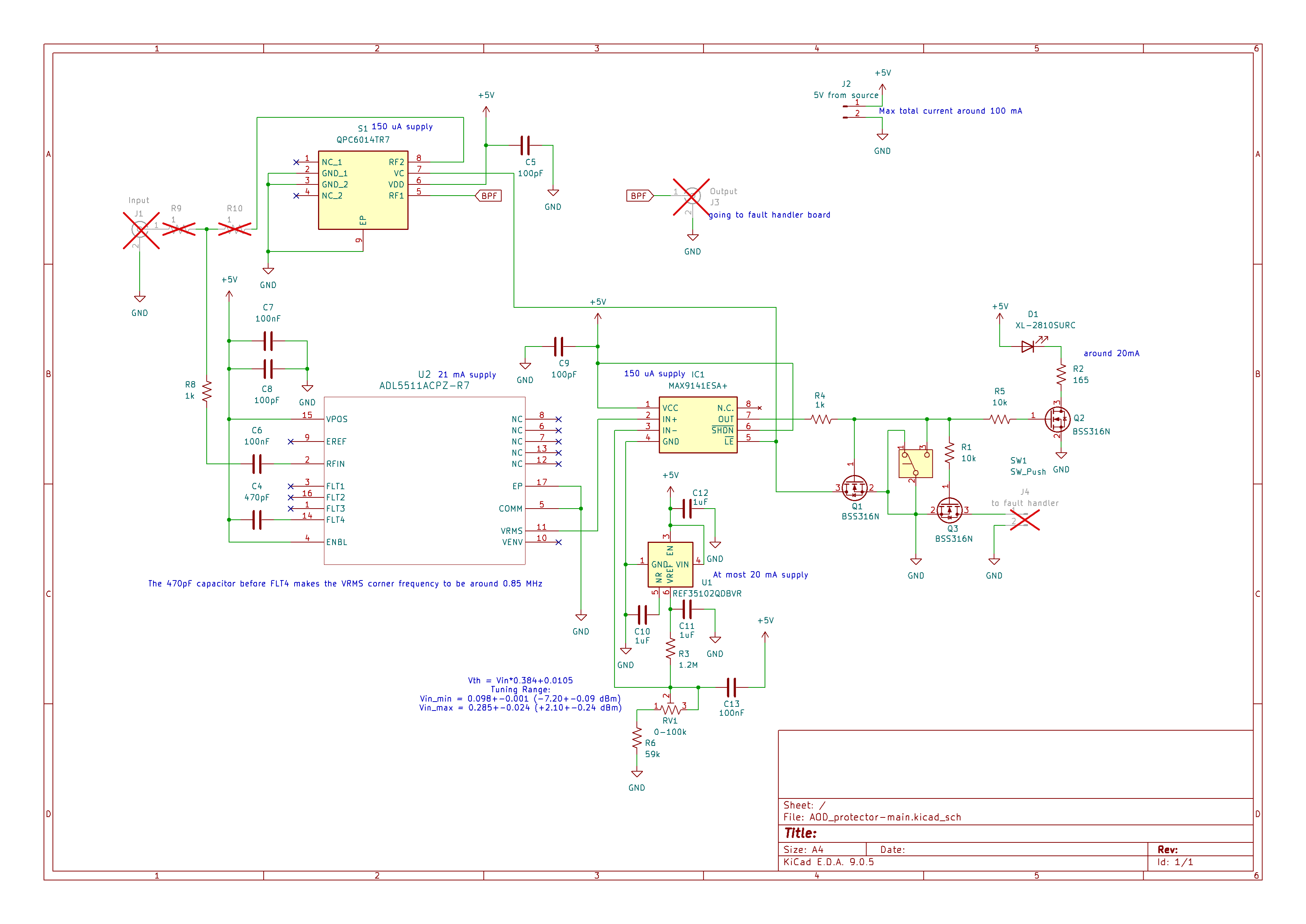
The sampling circuit diverts $3.85~%$ of the total power into the detection chip (ADL5511ACPZ-R7) which has a $250~\Omega$ input impedance. For low frequency (~ $100\textrm{ MHz}$) signals, the $V_{rms}$ output of the chip is $V_{rms}=1.92\overline{V_{in}}+11\textrm{ mV}$. The $\overline{V_{in}}$ is the averaged voltage of the input low-pass filtered over a corner frequency determined by the capacitor connected to pin FLT4: $f_{LP}=1/(800 \pi\ \Omega~(C_{FLT4}+20\textrm{ pF}))$. In our case with $C_{FLT4}=470\textrm{ pF}$, $f_{LP}=812\textrm{ kHz}$.
The output of the chip is fed into a comparator (MAX9141ESA+) whose inverting input is set by a voltage reference and a variable voltage divider. With all the components taken into consideration, we have $V_{th}\ge0.384\overline{V_{in}}+10.5\textrm{ mV}$, and the trimpot should allow us to tune the threshold of the rf power from $-7\textrm{ dBm}$ to $2\textrm{ dBm}$ measured at the power divider. The remaining circuit and the rf switch will contribute an additional insertion loss of around $0.8\textrm{ dB}$ at low rf frequency. It is worth noting that the estimated total insertion loss is around $0.98\textrm{ dB}$.
When the voltage goes beyond the threshold, the comparator will engage a latch, disable the rf switch, send a flag to the fault-handler board, and turn on the on-board red LED. The status of the comparator can be reset by the pushbutton manually.
The threshold's dynamic range can be adjusted by changing the resistors R3, R6, and the potentiometer RV1. The three resistors together form a voltage divider that outputs the desired $V_{th}$ from the $1.024~\textrm{V}$ voltage reference.
Together with the discussion about the rf power, $V_{th}$, and insertion loss in the previous paragraphs, the rf power threshold measured at the output port in dBm can be derived as follows:
$$20\log_{10}\left(10.24\frac{R_6+RV_1}{R_3+R_6+RV_1}-0.105\right)\textrm{ dBm}+0.52\textrm{ dBm}$$
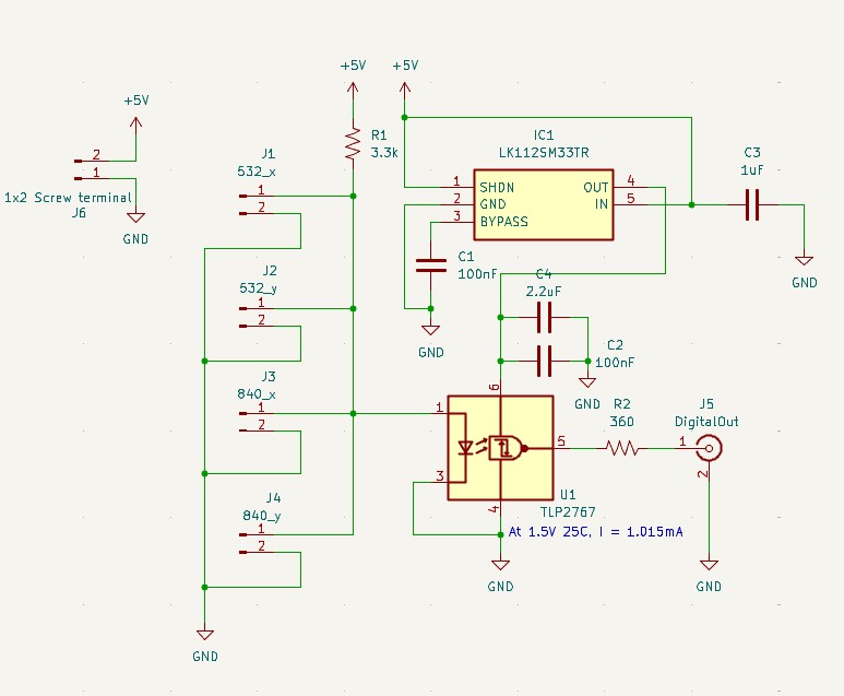
The fault handler board collectively receives the flag from the 4 main boards with an OR logic. When there is an over-threshold incident occurs on one of the main boards, the anode voltage of the optocoupler (TLP2767) will be pulled down and a $3.3\textrm{ V}$ voltage will be sent to the output BNC connector.
The power board filters the input 5V DC power line from a switching AC-DC adapter and distributes it to multiple boards. The filtering circuit is adapted from the Jane project (for the KiCad version of the design, contact Alessandro Restelli).
Ideally we want to implement a bandpass filter to suppress signals outside the operational bandwidth of the AOD for safety. With that in mind I designed a 5-order Butterworth bandpass filter for the two kinds of AOD we use respectively. Please refer to the Qucs file and board design for the details.
| Qty | Value | Footprint | References |
|---|---|---|---|
| 3 | 100nF | Capacitor_SMD:C_0603_1608Metric | C6, C7, C13 |
| 3 | 100pF | Capacitor_SMD:C_0402_1005Metric | C5, C8, C9 |
| 3 | 1uF | Capacitor_SMD:C_0603_1608Metric | C10, C11, C12 |
| 3 | BSS316N | Package_TO_SOT_SMD:SOT-23 | Q1, Q2, Q3 |
| 2 | 1 | Resistor_SMD:R_0402_1005Metric | R9, R10 |
| 2 | 10k | Resistor_SMD:R_0402_1005Metric | R1, R5 |
| 2 | 1k | Resistor_SMD:R_0402_1005Metric | R4, R8 |
| 1 | 0-100k | Custom_libs:RES-ADJ-TH_3296X | RV1 |
| 1 | 1.2M | Resistor_SMD:R_0603_1608Metric | R3 |
| 1 | 165 | Resistor_SMD:R_0603_1608Metric | R2 |
| 1 | 470pF | Capacitor_SMD:C_0402_1005Metric | C4 |
| 1 | 59k | Resistor_SMD:R_0402_1005Metric | R6 |
| 1 | 5V from source | Custom_libs:CONN-TH_2P-P2.54_MX128-2.54-GN01-02P-CU-Y-A | J2 |
| 1 | ADL5511ACPZ-R7 | Custom_libs:CP_16_22_ADI | U2 |
| 1 | Input | Custom_libs:BNC_Amphenol_031-6233_EdgeMount | J1 |
| 1 | MAX9141ESA+ | Custom_libs:SOIC127P600X175-8N | IC1 |
| 1 | Output | Custom_libs:BNC_Amphenol_031-6233_EdgeMount | J3 |
| 1 | QPC6014TR7 | Custom_libs:SON50P200X200X90-9N-D | S1 |
| 1 | REF35102QDBVR | Package_TO_SOT_SMD:SOT-23-6 | U1 |
| 1 | SW_Push | Custom_libs:SW-TH_TK-6580B-2 | SW1 |
| 1 | XL-2810SURC | Custom_libs:LED-SMD_L3.5-W1.4-FD-1 | D1 |
| 1 | to fault handler | Connector_PinHeader_2.54mm:PinHeader_1x02_P2.54mm_Vertical | J4 |
JQIamo/AOD_protector
The protection circuit for the acousto-optic deflectors used for tweezers

JQIamo/AOD_protector
The protection circuit for the acousto-optic deflectors used for tweezers

JQIamo/AOD_protector
The protection circuit for the acousto-optic deflectors used for tweezers

JQIamo/AOD_protector
The protection circuit for the acousto-optic deflectors used for tweezers


DennisRathgeb/doppler-radar-detector
24 GHz CW Doppler + FMCW radar detector: STM32F429 + ESP32 + TouchGFX live UI, CMSIS-DSP FFT, FastAPI backend, YOLOv8 angle-of-arrival sensor fusion desktop app. ZHAW PM4 team project.


It measures 35 × 23 mm and has 4 copper layers, 1.6 mm thick.
33 parts, built around the ADL5511ACPZ-R7, QPC6014TR7, MAX9141ESA+ and BSS316N. The full list of its parts is on this page, with links to each part's symbol and footprint where PCBKit's library has them.
From the JQIamo/AOD_protector repository on GitHub, at the commit this page was made from: the board is AOD_protector-main/AOD_protector-main.kicad_pcb and its schematic AOD_protector-BPF_testboard/532Test_board/532Test_board.kicad_sch. PCBKit opens the board in the browser, with nothing to install.
Its repository publishes it under the MIT licence: you may reuse it on that licence's terms (keep the author's notice, and for a copyleft licence share your changes alike).