
2 layers71.1 × 50.8 mm
9V Battery Status Indicator Circuit
JKCadilo14-CpE/DIY-Circuits
Collection of electronic circuits I designed, tested, and documented using KiCad
12 partsMIT

 JKCadilo14-CpE/DIY-Circuits
Collection of electronic circuits I designed, tested, and documented using KiCad
Water level indicator is an open-source printed circuit board by JKCadilo14-CpE, from the JKCadilo14-CpE/DIY-Circuits repository on GitHub, published under the MIT licence. It is a 2-layer board of 101.6 × 71.1 mm with 18 parts on 17 nets, routed with 64 tracks and 0 vias.
It is built around the BC547. Its parts include 7 resistors, 4 transistors, 3 diodes and 3 connectors.
A beginner-friendly automatic sanitizer pump controller using an IR sensor module input, TIP32C transistor switching stage, and DC pump connection.
| Item | Details |
|---|---|
| Status | Educational Prototype |
| Difficulty | Intermediate |
| Hardware Tested | Breadboard and PCB prototype assembled and functionally tested |
| Supply Voltage | Prototype tested with a 9V battery; exact operating range not characterized |
| KiCad Compatibility | Schematic KiCad 10.0 metadata; PCB KiCad 9.0 metadata |
| License | MIT License |
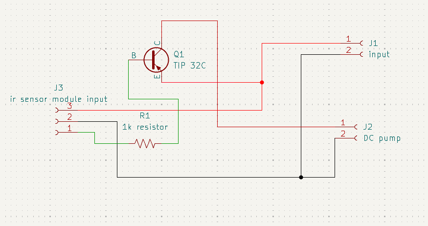
This project demonstrates a simple sensor-controlled pump switch. The schematic provides an IR sensor module input at J3, a TIP32C transistor switching stage, and a DC pump connection at J2.
When the sensor module input changes state, the transistor stage responds and controls the pump connection. Verified prototype behavior is documented separately under Verified Prototype Observations.
This project is intended for educational demonstration only and must not be relied upon as a commercial or medical hand-sanitizing device.
| Reference | Component | Role in the Circuit |
|---|---|---|
| J1 | input connector | Main circuit input connection shown in the schematic. |
| J2 | DC pump connector | Output connection for the DC pump load. |
| J3 | ir sensor module input connector | Interface for the external sensor-module signal. |
| R1 | 1k resistor | Resistor in the sensor-to-transistor control path. |
| Q1 | TIP 32C | PNP transistor switching stage used to control the pump connection. |
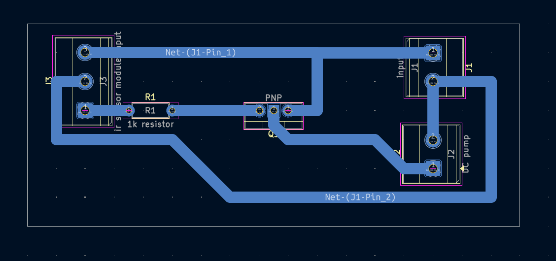
The PCB footprint identifies Q1 generically as PNP, while the schematic value identifies the intended transistor as TIP 32C.
The schematic shows J3 as the IR sensor module input. That input is routed through R1, labeled 1k resistor, to Q1.
Q1 is identified in the schematic as TIP 32C, a PNP transistor used as the switching stage for the pump connection. J2 is labeled DC pump, indicating the output load connection.
The commercially available IR obstacle sensor module used in the verified prototype is documented as a build observation. It should not be treated as a PCB schematic component beyond the schematic interface at J3.
The repository does not document measured pump current, pump flow rate, sanitizer volume, response time, battery life, or certified medical suitability.
Many sensor modules provide an output signal that can be used to control a separate load-switching circuit. In this project, the sensor-module signal enters the PCB at J3.
R1 provides the connection path from the sensor input toward the transistor stage. Q1 then acts as the switching device that controls the DC pump connection at J2.
The sensor module detects the hand in the prototype, but the PCB itself is mainly a pump-control board. This separation is important: the commercial sensor module is part of the verified prototype setup, while the KiCad schematic documents the PCB interface and switching stage.
This section describes the intended schematic operation. Detailed prototype lessons are listed separately under Verified Prototype Observations.
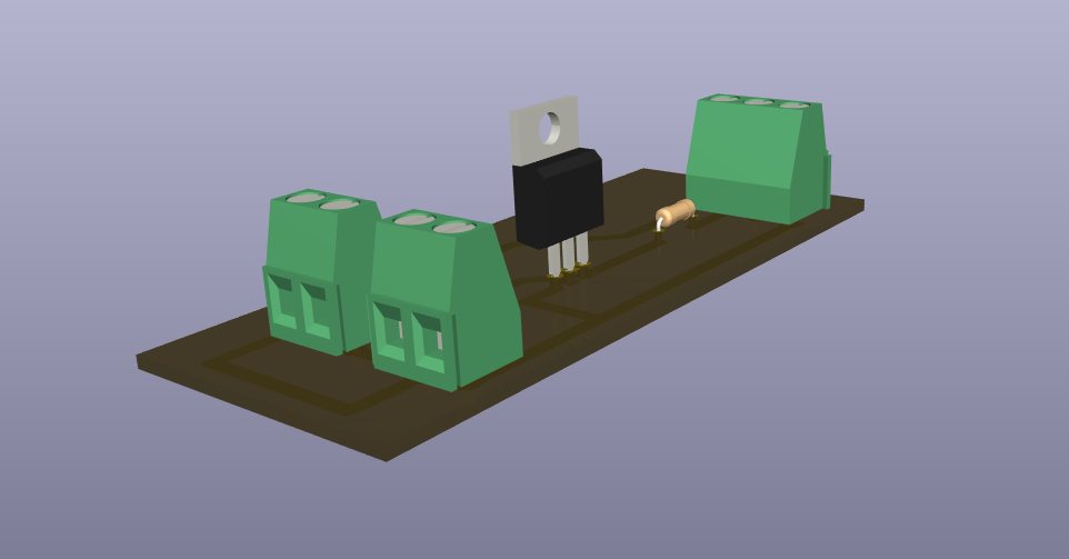
Finished hardware photographs will be added after the completed prototype is photographed.
| Check | What to Verify |
|---|---|
| Battery polarity | Confirm correct 9V battery polarity before connection. |
| Battery voltage | Measure the 9V battery with a multimeter before troubleshooting. |
| Transistor orientation | Confirm Q1 matches the TIP32C pinout and PCB footprint. |
| Sensor-module wiring | Confirm the external sensor module is connected to J3 correctly. |
| Pump polarity | Confirm the DC pump is connected to J2 with the intended polarity. |
| Resistor value | Confirm R1 is 1k. |
| Solder bridges | Inspect adjacent pads and traces for accidental shorts. |
| Continuity test | Check for unintended shorts before connecting a battery. |
| Liquid isolation | Keep the PCB, battery, and exposed electrical connections dry. |
This project is intended for educational demonstration only and must not be relied upon as a commercial or medical hand-sanitizing device.
Suggested test procedure:
Successful test indicators:
The following items are Verified Prototype Observations from the physical build. They extend beyond what is explicitly guaranteed by the KiCad schematic.
The verified prototype used a commercially available IR obstacle sensor module. That module is documented as part of the verified prototype setup and should not be interpreted as a PCB schematic component.
A DIY version of the sensor module could be explored as a future modification, but this README documents the verified prototype using the commercial IR obstacle sensor module.
The PCB prototype used a standard terminal block. Female-to-male jumper wires were used during prototype testing to connect the commercial IR obstacle sensor module to J3.
Builders who prefer detachable wiring may use compatible connector solutions that match the PCB terminals without modifying the PCB design.
The following are possible future improvements inspired by observations made during prototype testing. They are not planned or verified features in this README:
| Symptom | Checks |
|---|---|
| Pump never activates | Check battery polarity and voltage, J3 sensor wiring, Q1 orientation, R1 value, pump polarity, and solder joints. |
| Pump always runs | Check sensor-module wiring, Q1 orientation, solder bridges, and whether the sensor output is staying active. |
| Sensor does not detect a hand | Verify sensor-module power and wiring, then compare with the verified breadboard prototype. |
| Intermittent activation | Check battery voltage, jumper-wire connections, sensor alignment, solder joints, and pump wiring. |
| Pump activates but runs weakly or inconsistently | Check battery voltage, pump polarity, and sensor wiring. |
| Incorrect transistor orientation | Check the TIP32C datasheet and confirm the pinout matches the PCB footprint. |
| Incorrect pump polarity | Disconnect power and verify the pump wiring at J2 before testing again. |
| Cold solder joints | Reinspect dull, cracked, or incomplete solder joints after disconnecting power. |
| Breadboard works but PCB does not | Compare PCB assembly against the verified breadboard prototype, then inspect solder bridges, cold solder joints, component placement, PCB continuity, and wiring. |
| Incorrect battery voltage | Measure the 9V battery with a multimeter and use a fresh or fully charged battery for demonstration testing. |
| Excessive motor noise | Treat pump noise as a practical prototype observation; check pump mounting, wiring, and battery condition without assuming a measured noise level. |
| File | Description |
|---|---|
automatic hand sanitizer.kicad_pro | KiCad project file. Open this file in KiCad. |
automatic hand sanitizer.kicad_sch | KiCad schematic source. |
automatic hand sanitizer.kicad_pcb | KiCad PCB layout source. |
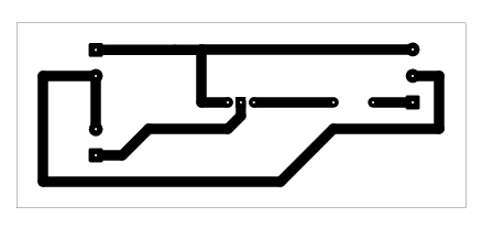
automatic hand sanitizer-B_Cu.pdf | Existing B.Cu PDF plot export. |
automatic hand sanitizer-B_Cu-2.pdf | Existing B.Cu PDF plot export. |
This repository is intended for educational and personal learning purposes. The circuits, schematics, PCB layouts, fabrication files, and documentation are shared to help students understand electronics design, PCB fabrication, and circuit analysis.
Please do not submit these projects as your own academic work. If you use any design or idea from this repository, make sure you understand how it works, adapt it to your own requirements, and follow your institution's academic integrity policies.
The goal of this repository is to encourage learning, experimentation, and skill development—not to replace your own design process.
If you are using this repository for a class, use it as a reference to understand concepts and improve your own designs. Always create and submit work that complies with your instructor's requirements and your institution's academic integrity policies.
| Version | Changes |
|---|---|
| 2.0.0 | Updated README to follow the Version 2.0.0 documentation standard with expanded project information, circuit explanation, theory, assembly guidance, testing notes, practical build notes, troubleshooting, gallery, downloads, and repository notices. |
This project is released under the MIT License. See the repository LICENSE.
| Qty | Value | Footprint | References |
|---|---|---|---|
| 7 | 100 ohms | Resistor_THT:R_Axial_DIN0207_L6.3mm_D2.5mm_P7.62mm_Horizontal | R1, R2, R3, R4, R5, R6, R7 |
| 4 | BC547 | Package_TO_SOT_THT:TO-92_Inline | Q1, Q2, Q3, Q4 |
| 3 | LED | LED_THT:LED_D3.0mm | D1, D2, D3 |
| 1 | Buzzer | Buzzer_Beeper:Buzzer_15x7.5RM7.6 | BZ1 |
| 1 | input | TerminalBlock_Phoenix:TerminalBlock_Phoenix_MKDS-1,5-2_1x02_P5.00mm_Horizontal | J3 |
| 1 | out | TerminalBlock_Phoenix:TerminalBlock_Phoenix_MKDS-1,5-2_1x02_P5.00mm_Horizontal | J2 |
| 1 | out | TerminalBlock_Phoenix:TerminalBlock_Phoenix_MKDS-1,5-3-5.08_1x03_P5.08mm_Horizontal | J1 |
JKCadilo14-CpE/DIY-Circuits
Collection of electronic circuits I designed, tested, and documented using KiCad

JKCadilo14-CpE/DIY-Circuits
Collection of electronic circuits I designed, tested, and documented using KiCad

JKCadilo14-CpE/DIY-Circuits
Collection of electronic circuits I designed, tested, and documented using KiCad

JKCadilo14-CpE/DIY-Circuits
Collection of electronic circuits I designed, tested, and documented using KiCad

JKCadilo14-CpE/DIY-Circuits
Collection of electronic circuits I designed, tested, and documented using KiCad

JKCadilo14-CpE/DIY-Circuits
Collection of electronic circuits I designed, tested, and documented using KiCad

JKCadilo14-CpE/DIY-Circuits
Collection of electronic circuits I designed, tested, and documented using KiCad

JKCadilo14-CpE/DIY-Circuits
Collection of electronic circuits I designed, tested, and documented using KiCad

JKCadilo14-CpE/DIY-Circuits
Collection of electronic circuits I designed, tested, and documented using KiCad

JKCadilo14-CpE/DIY-Circuits
Collection of electronic circuits I designed, tested, and documented using KiCad

JKCadilo14-CpE/DIY-Circuits
Collection of electronic circuits I designed, tested, and documented using KiCad

github-linguist/linguist
Language Savant. If your repository's language is being reported incorrectly, send us a pull request!

dotnet/iot
This repo includes .NET Core implementations for various IoT boards, chips, displays and PCBs.

peterheinrich/InternetOverSpaghetti
Transmitting IP packages over a pair of spaghetti thus demonstrating how media independent IP really is.

tebl/RC6502-Apple-1-Replica
An expandable SBC-version of the Apple 1 computer, easy to get started with and lot of cool stuff that can be added to it!


ZeroPhone/ZeroPhone-PCBs
PCB files for ZeroPhone - for gerbers and schematics, go to "Releases" tab!

It measures 101.6 × 71.1 mm and has 2 copper layers, 1.6 mm thick.
18 parts, built around the BC547. The full list of its parts is on this page, with links to each part's symbol and footprint where PCBKit's library has them.
From the JKCadilo14-CpE/DIY-Circuits repository on GitHub, at the commit this page was made from: the board is Transistor Based/water level indicator/water level indicator.kicad_pcb and its schematic Transistor Based/9V Battery Status Indicator Circuit/9V Battery Status Indicator Circuit.kicad_sch. PCBKit opens the board in the browser, with nothing to install.
Its repository publishes it under the MIT licence: you may reuse it on that licence's terms (keep the author's notice, and for a copyleft licence share your changes alike).