2 layers139.7 × 88.9 mm
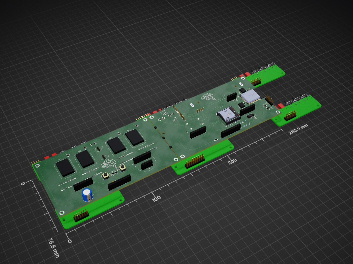
 Incomprehensible/Mad_RetroClock
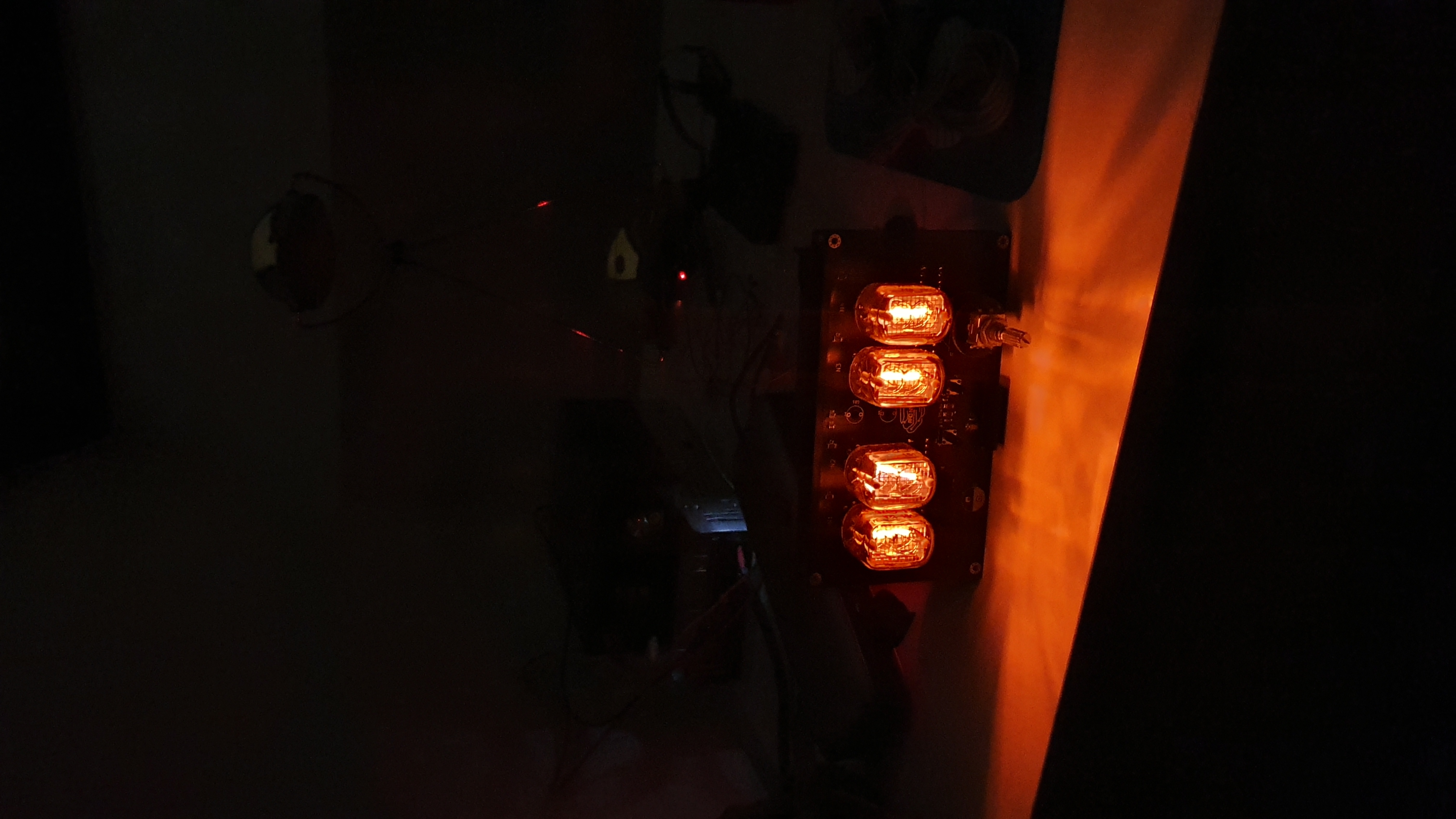
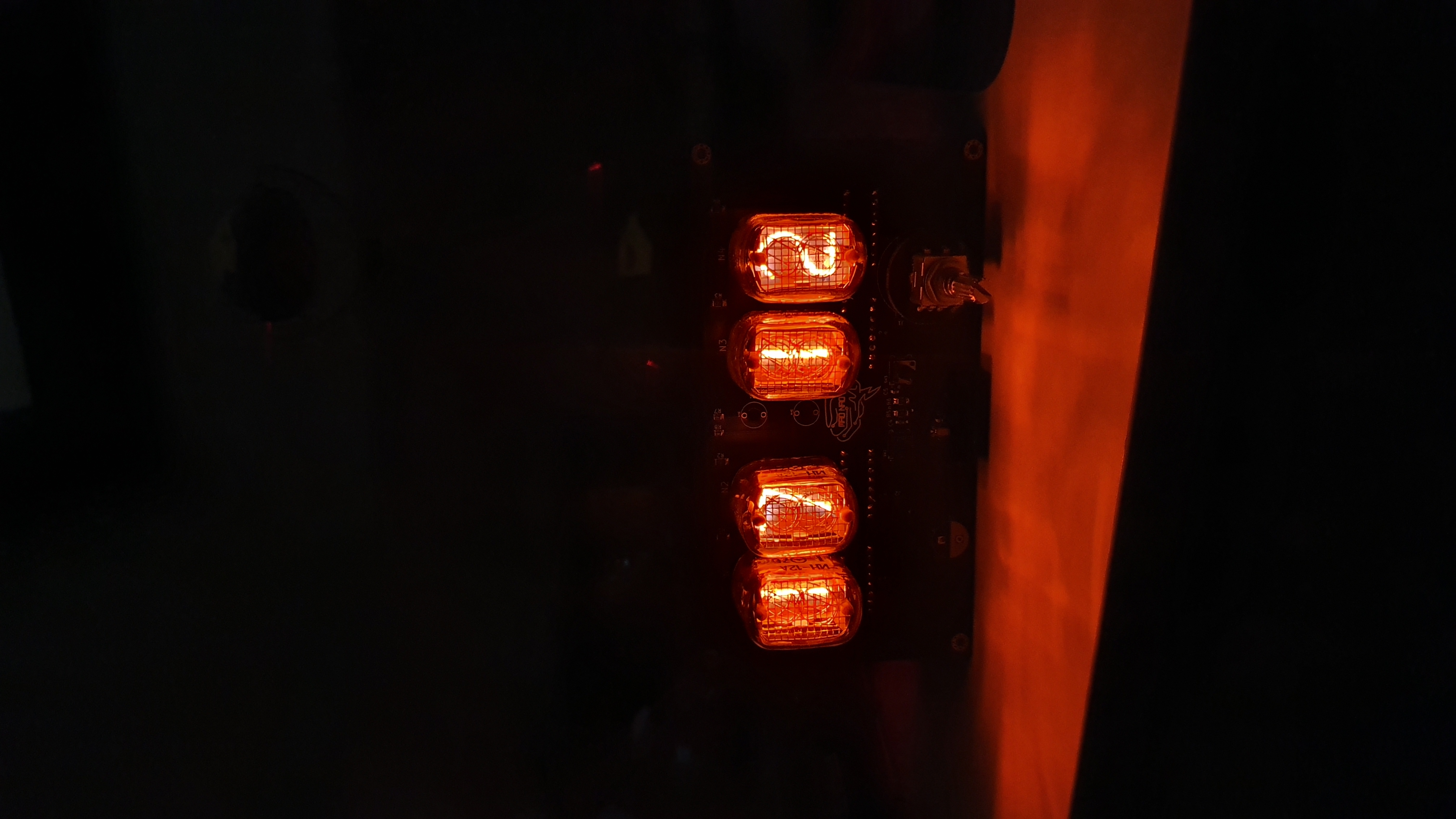
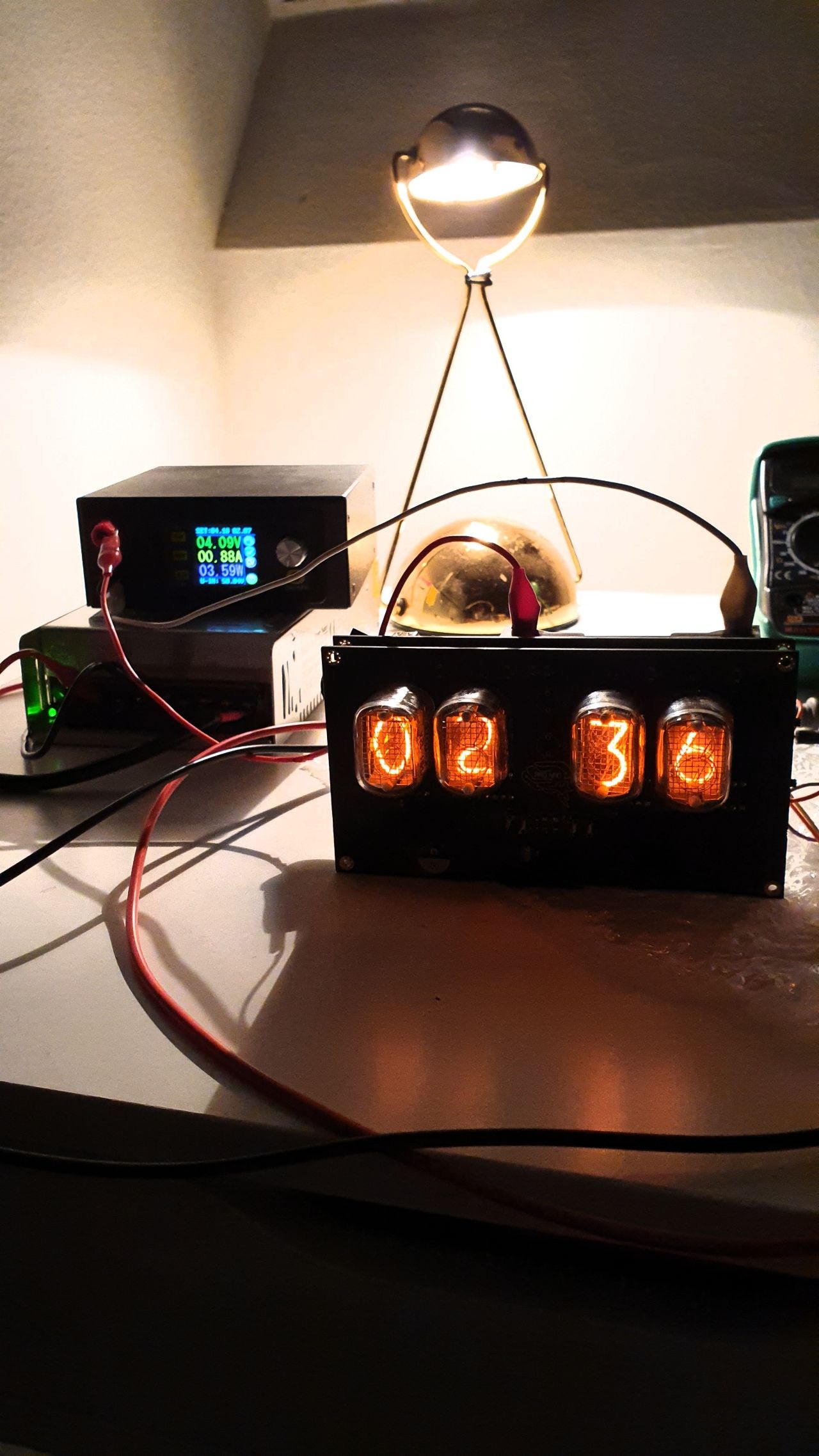
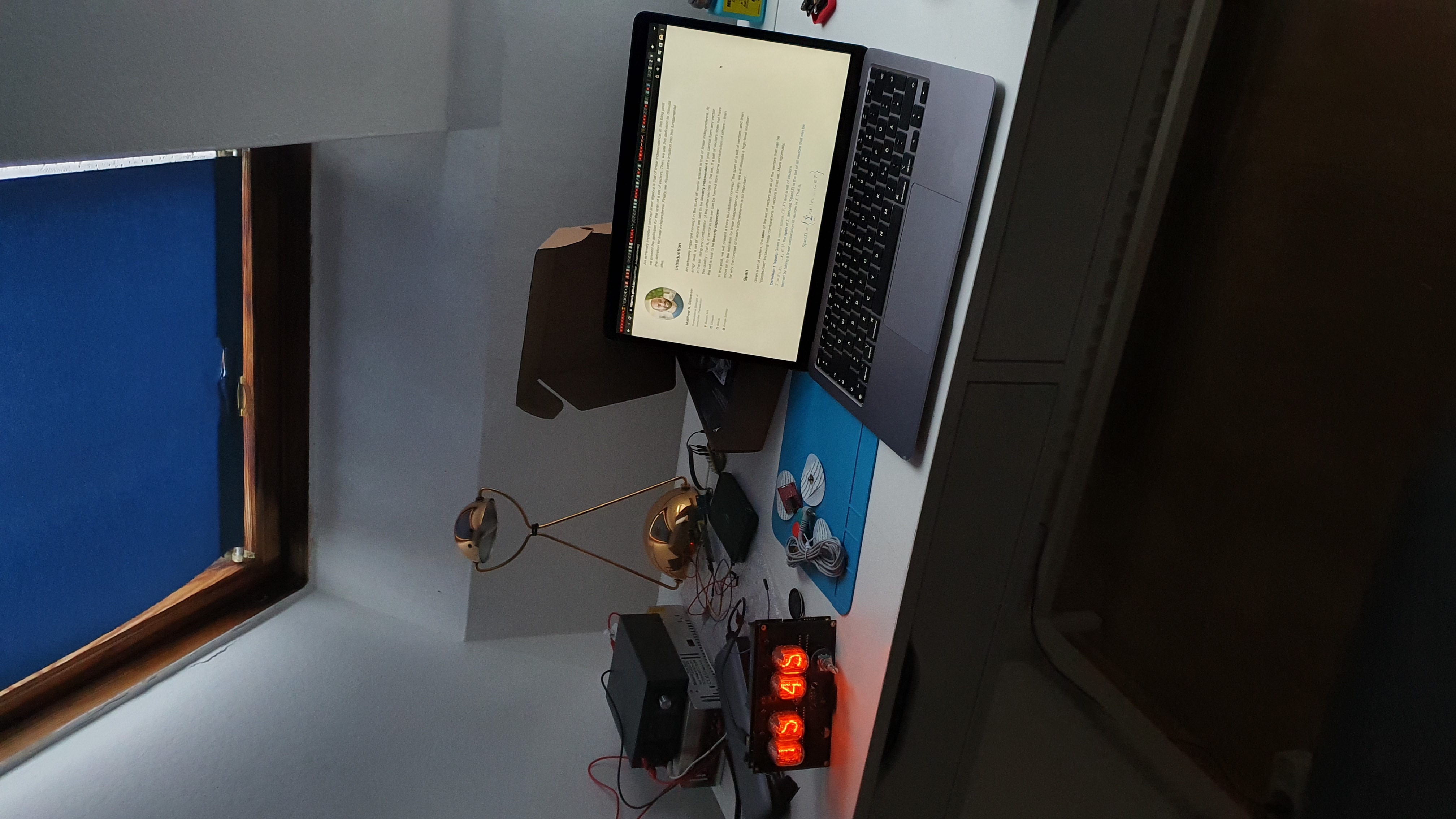
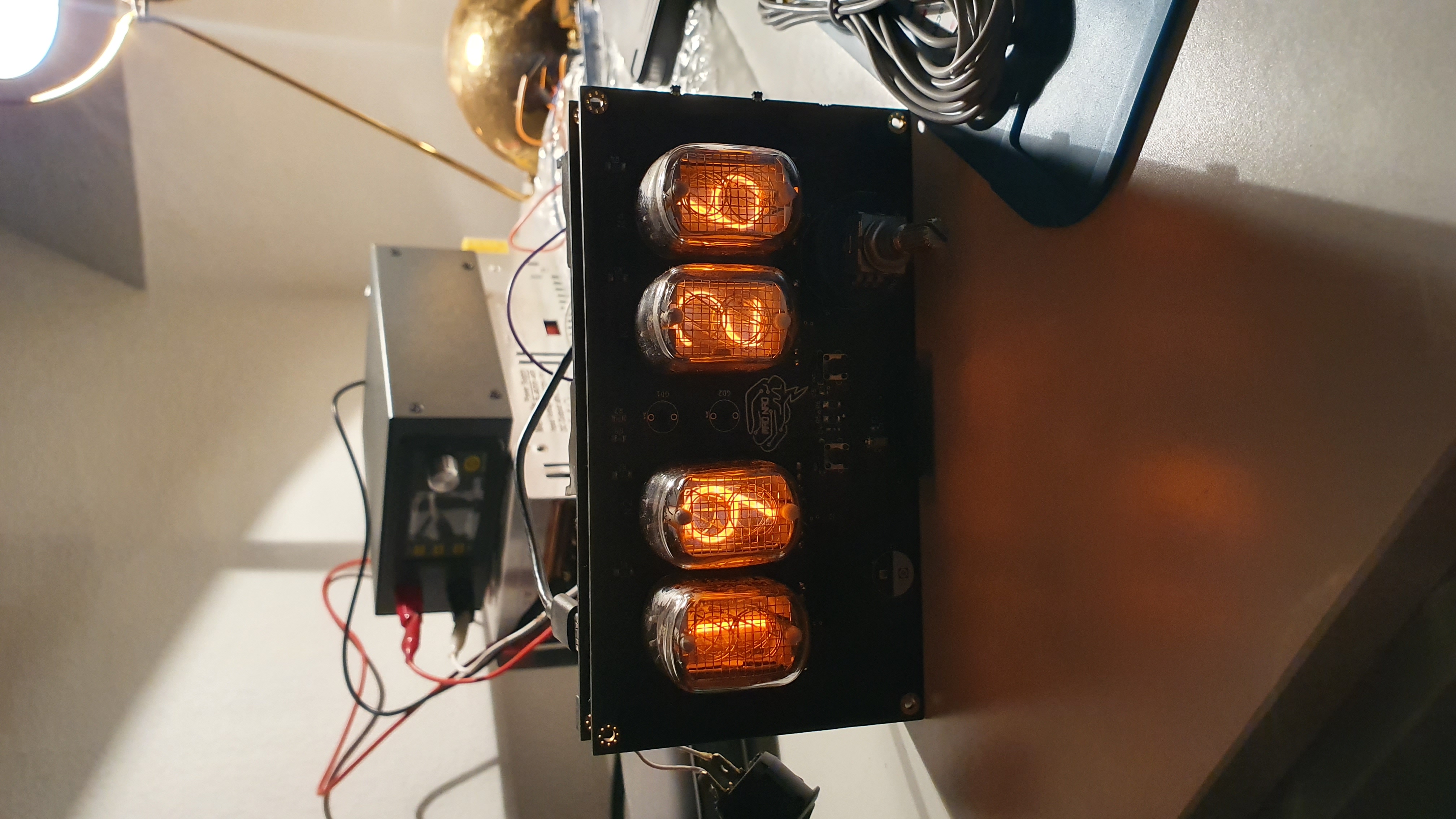
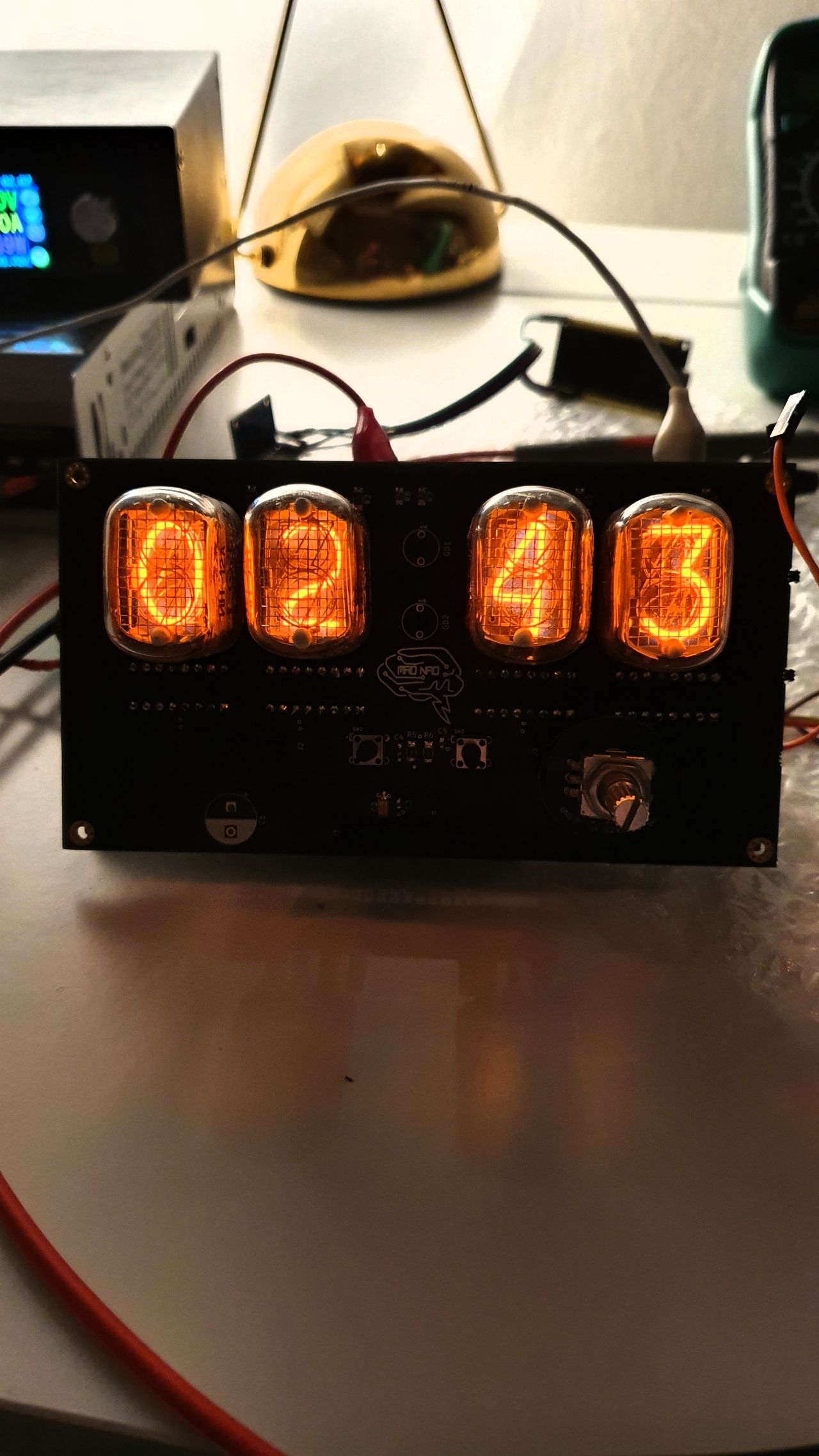
A stylish, soviet Nixie tubes-based stationary clock ✩ ⩇⩇:⩇⩇ ☾
Retro clock is an open-source printed circuit board by Incomprehensible, from the Incomprehensible/Mad_RetroClock repository on GitHub, published under the Apache-2.0 licence. It is a 2-layer board of 280.9 × 76.8 mm with 105 parts on 161 nets, routed with 1,053 tracks and 128 vias.
It is built around the ESP32-WROOM-32, AMS1117-5.0 and ESDA5V3L. Its parts include 29 resistors, 21 capacitors, 12 ICs, 9 connectors and 8 switches. It belongs with the lEDs and displays and retro computing and games boards and the ESP32 boards of this library.


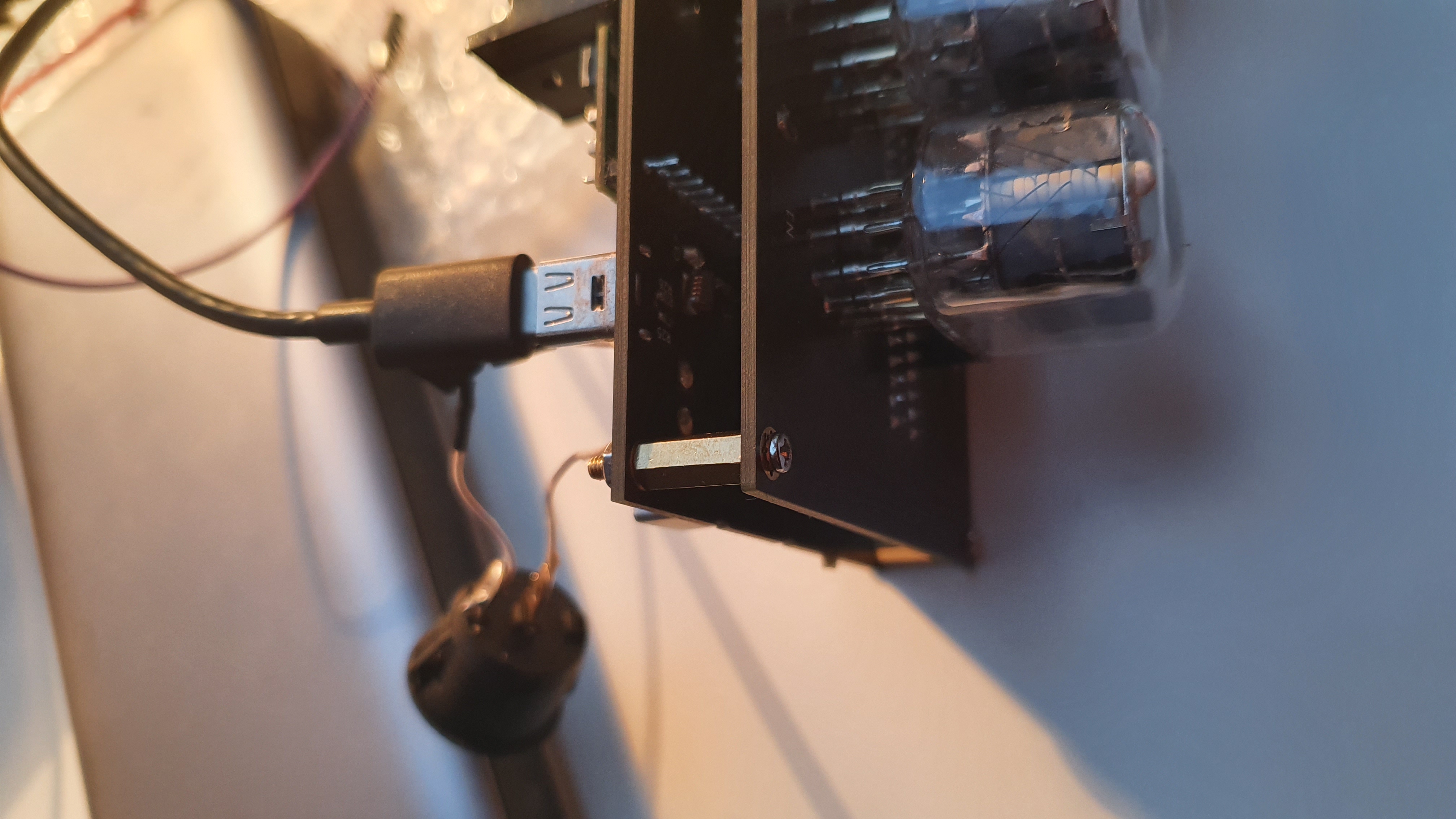
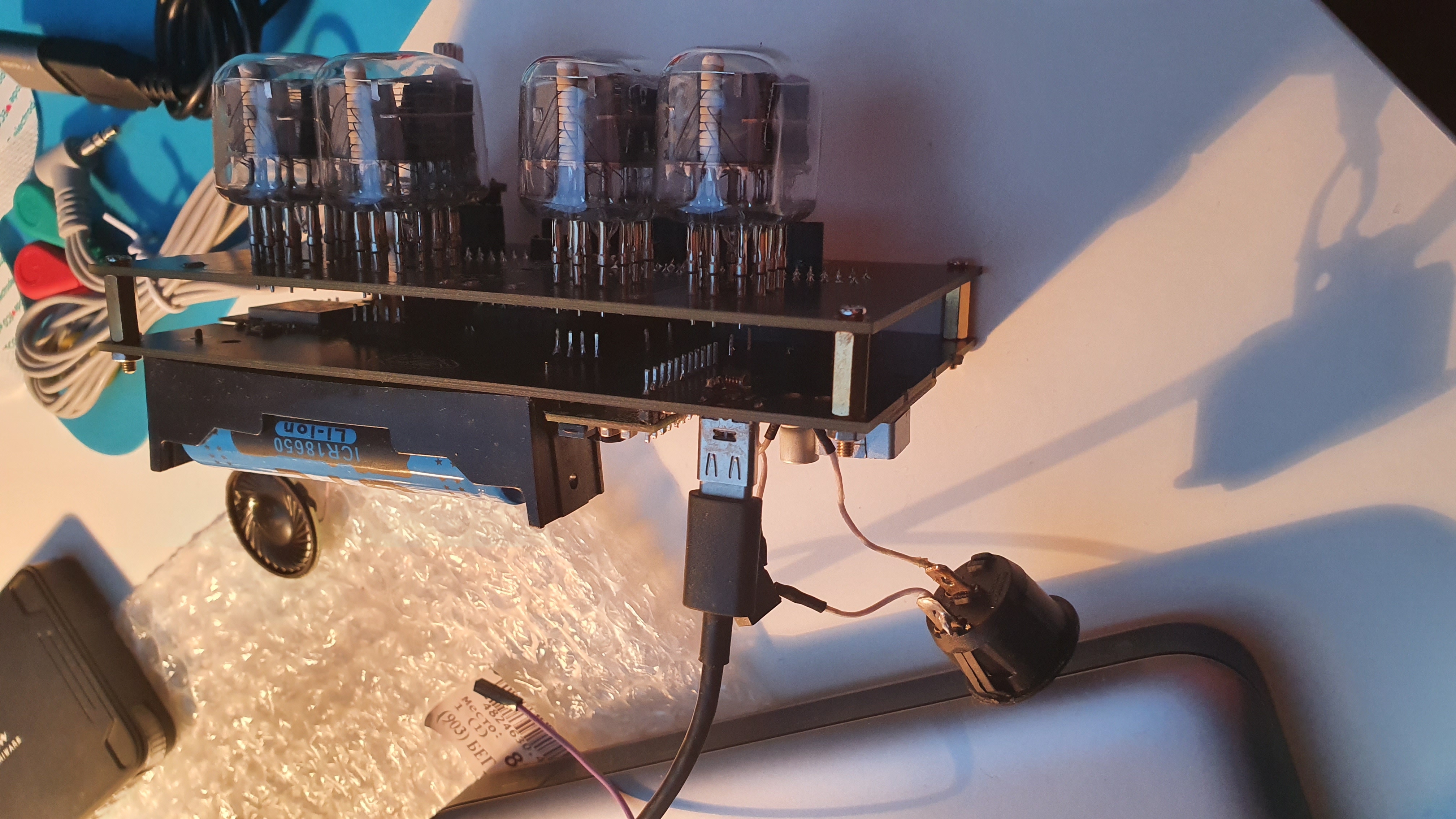
Powered via 5V USB-C interface. Provides a 2S Li-Ion battery pack for autonomous operation.
Made with 4 IN-12A Nixie Tubes denoting hours & minutes, and smaller INS-1 tubes as the dots.
Enabled with Wi-Fi connectivity for automatic time synchronization using the Network Time Protocol (NTP).
Functions as a simple clock and an alarm clock. User interface for the alarm setting is implemented with 2 Set/Unset buttons and rotary encoder.
There's an MP3-player onboard any melody can be programmed and set as an alarm call.


| Qty | Value | Footprint | References |
|---|---|---|---|
| 9 | 10k | Resistor_SMD:R_0603_1608Metric_Pad0.98x0.95mm_HandSolder | R9, R10, R11, R12, R13, R22, R27, R28, R29 |
| 8 | MountingHole | MountingHole:MountingHole_2.5mm_Pad_Via | H1, H2, H3, H4, H5, H6, H7, H8 |
| 6 | 0.1uF | Capacitor_SMD:C_0603_1608Metric_Pad1.08x0.95mm_HandSolder | C4, C5, C7, C11, C16, C21 |
| 6 | R | Resistor_SMD:R_0603_1608Metric_Pad0.98x0.95mm_HandSolder | R16, R17, R18, R19, R20, R21 |
| 5 | 10uF | Capacitor_SMD:C_0603_1608Metric_Pad1.08x0.95mm_HandSolder | C6, C13, C15, C18, C20 |
| 4 | 15k | Resistor_SMD:R_1206_3216Metric_Pad1.30x1.75mm_HandSolder | R1, R2, R3, R4 |
| 4 | IN-12A | Retro_clock:IN-12A | N1, N2, N3, N4 |
| 4 | K155ID1 | Package_DIP:DIP-16_W7.62mm | U1, U2, U3, U4 |
| 3 | VAL** | Panelization:mouse-bite-1mm-slot | mouse-bite-1mm-slot, mouse-bite-1mm-slot, mouse-bite-1mm-slot |
| 2 | 10k | Resistor_SMD:R_1206_3216Metric_Pad1.30x1.75mm_HandSolder | R5, R6 |
| 2 | 1uF | Capacitor_SMD:C_0603_1608Metric_Pad1.08x0.95mm_HandSolder | C8, C9 |
| 2 | 22uF | Capacitor_Tantalum_SMD:CP_EIA-3216-10_Kemet-I_Pad1.58x1.35mm_HandSolder | C2, C14 |
| 2 | 240k | Resistor_SMD:R_0805_2012Metric_Pad1.20x1.40mm_HandSolder | R7, R8 |
| 2 | 250 | Resistor_SMD:R_0603_1608Metric_Pad0.98x0.95mm_HandSolder | R14, R15 |
| 2 | 4.7k | Resistor_SMD:R_0603_1608Metric_Pad0.98x0.95mm_HandSolder | R23, R24 |
| 2 | 5.1k | Resistor_SMD:R_0603_1608Metric_Pad0.98x0.95mm_HandSolder | R25, R26 |
| 2 | Conn_01x08_Female | Connector_PinSocket_2.54mm:PinSocket_1x08_P2.54mm_Vertical | J1, J2 |
| 2 | INS-1 | Retro_clock:INS-1 | GD1, GD2 |
| 2 | LOGO | NadSilk:brain_logo | G***, G*** |
| 2 | Q_NPN_BCE | Package_TO_SOT_SMD:SOT-23_Handsoldering | Q1, Q2 |
| 2 | Reserv | Capacitor_SMD:C_0603_1608Metric_Pad1.08x0.95mm_HandSolder | C12, C19 |
| 1 | 100nF | Capacitor_SMD:C_0603_1608Metric_Pad1.08x0.95mm_HandSolder | C3 |
| 1 | 10uF | Capacitor_SMD:C_0805_2012Metric_Pad1.18x1.45mm_HandSolder | C17 |
| 1 | 18560 | Retro_clock:BAT_BH-18650-PC | BT1 |
| 1 | 22uF | Capacitor_THT:CP_Radial_D10.0mm_P5.00mm | C1 |
| 1 | 74HC164D,653 | Retro_clock:SOIC127P600X175-14N | U6 |
| 1 | AMS1117-5.0 | Package_TO_SOT_SMD:SOT-223-3_TabPin2 | U8 |
| 1 | Boot | Retro_clock:SW_TS-1187A-B-A-B | SW4 |
| 1 | Cancel | Retro_clock:KLS7-TS6601-13.0-180 | SW3 |
| 1 | Conn_01x10_Female | Connector_PinSocket_2.54mm:PinSocket_1x10_P2.54mm_Vertical | J3 |
| 1 | DD04CPMA | Retro_clock:DD04CPMA | U9 |
| 1 | DD04CVSA | Retro_clock:DD04CVSA | U10 |
| 1 | DFPlayer_mini | Retro_clock:MODULE_DFR0299 | U7 |
| 1 | ESDA5V3L | Package_TO_SOT_SMD:SOT-23 | D1 |
| 1 | ESP32-WROOM-32 | Retro_clock:MODULE_ESP32-WROOM-32 | U5 |
| 1 | Enter | Retro_clock:KLS7-TS6601-13.0-180 | SW2 |
| 1 | F2.5A | Fuse:Fuse_1206_3216Metric_Pad1.42x1.75mm_HandSolder | F1 |
| 1 | F40mA | Fuse:Fuse_1206_3216Metric_Pad1.42x1.75mm_HandSolder | F2 |
| 1 | Flash | Connector_PinHeader_2.54mm:PinHeader_1x05_P2.54mm_Vertical | J8 |
| 1 | Mini360 | Retro_clock:Mini360_step-down | U12 |
| 1 | NIXIE_1_2_OUT | Connector_PinSocket_2.54mm:PinSocket_1x08_P2.54mm_Vertical | J5 |
| 1 | NIXIE_3_4_OUT | Connector_PinSocket_2.54mm:PinSocket_1x08_P2.54mm_Vertical | J6 |
| 1 | Nixie-PSU | Retro_clock:Nixie-PSU | U11 |
| 1 | PWR_SW | Retro_clock:PWR_SWITCH | SW8 |
| 1 | Reserved_p | Capacitor_SMD:C_0603_1608Metric_Pad1.08x0.95mm_HandSolder | C10 |
| 1 | Rotary_Encoder_Switch | Retro_clock:Encoder | SW1 |
| 1 | Rst | Retro_clock:SW_TS-1187A-B-A-B | SW5 |
| 1 | Speaker | Retro_clock:Speaker_conn | LS1 |
| 1 | USB_C_Plug | Retro_clock:usb_c_receptable_hro_type-c-31-m-17 | P1 |
| 1 | VDRIVE_OUT | Connector_PinSocket_2.54mm:PinSocket_1x10_P2.54mm_Vertical | J4 |
| 1 | Volume_down | Retro_clock:KLS7-TS6601-13.0-180 | SW6 |
| 1 | Volume_up | Retro_clock:KLS7-TS6601-13.0-180 | SW7 |
| 1 | mini-DS-3231 | Retro_clock:DS3231-Mini | J7 |

Ezecarp36/Robot-Sumo-Sami
Proyecto de robot sumo para participar en la LNR 2023

Ajith-Anand-R/Smart-Home-Controller
Full-stack IoT home automation system with ESP32 firmware, Google Apps Script backend, web dashboard, and Flutter mobile app.

Diegoapp55/Proyecto-Sistemas-Embebidos-Smash-Rows
Repositorio para el proyecto de Sistemas Embebidos 2022-2: Smash Rows

Capibator/hardware
deals with research material on hardware, schematic, pcb design and bom etc.

dani0421/Compostaje
El SDA se conecta al pin 33 del ESP32 y el SCL al pin 36 de ESP32, cabe resaltar que en la placa no quedaran orificios para la pantalla, unicamente los pines para hacer la conexión.


Ezecarp36/RobotLaberinto_G2
Proyecto de robot laberinto para competir en la LNR 2023
It measures 280.9 × 76.8 mm and has 2 copper layers, 1.6 mm thick.
105 parts, built around the ESP32-WROOM-32, AMS1117-5.0 and ESDA5V3L. The full list of its parts is on this page, with links to each part's symbol and footprint where PCBKit's library has them.
From the Incomprehensible/Mad_RetroClock repository on GitHub, at the commit this page was made from: the board is Retro_clock.kicad_pcb and its schematic Back_PCB.kicad_sch. PCBKit opens the board in the browser, with nothing to install.
Its repository publishes it under the Apache-2.0 licence: you may reuse it on that licence's terms (keep the author's notice, and for a copyleft licence share your changes alike).