
2 layers95 × 60 mm
 Ajith-Anand-R/Smart-Home-Controller1
Full-stack IoT home automation system with ESP32 firmware, Google Apps Script backend, web dashboard, and Flutter mobile app.
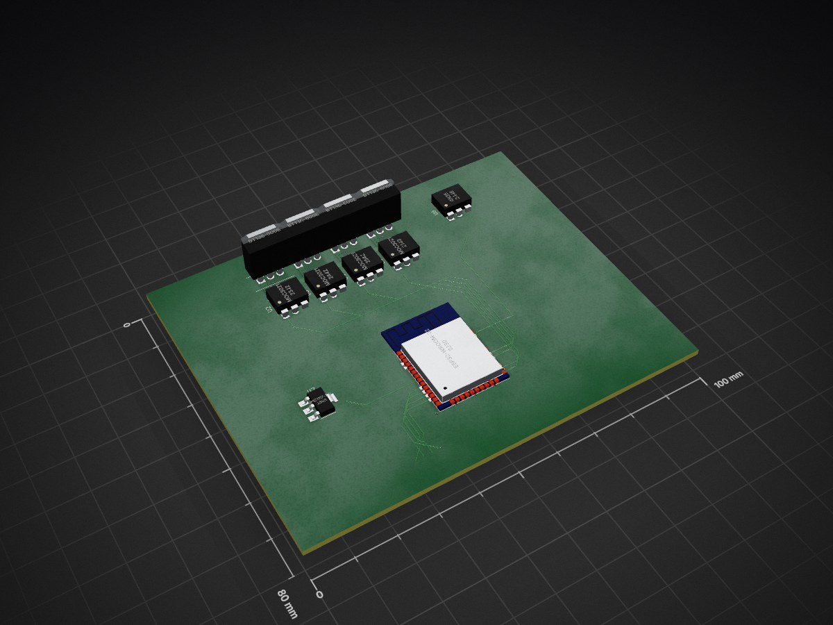
Smart Home Controller is an open-source printed circuit board by Ajith-Anand-R, from the Ajith-Anand-R/Smart-Home-Controller repository on GitHub, published under the MIT licence. It is a 2-layer board of 100 × 80 mm with 11 parts on 36 nets, routed with 60 tracks and 4 vias.
It is built around the ESP32-WROOM-32, BT136-600E and MOC3021, with the AMS1117-5.0 among its other parts. Its parts include 7 ICs and 4 transistors. It belongs with the home automation and IoT boards and the ESP32 boards of this library.


"# Smart Home Controller


Full-stack IoT home automation system with ESP32 firmware, Google Apps Script backend, web dashboard, and Flutter mobile app. Controls 4 AC load channels via TRIAC phase-angle dimming with cloud synchronization, scheduling, and Amazon Alexa voice control.
Maturity: Portfolio project / advanced prototype Tested on: ESP32-WROOM-32 with custom TRIAC controller board Known limitations:
What works:
Not yet implemented:
Web dashboard with real-time device control and system statistics
backend/google-apps-script/ files to a Google Apps Script project and deploy as a web app. See Deployment Guide.firmware/main/main.ino in Arduino IDE, set your Apps Script URL, and upload to ESP32. See Installation Guide.flutter build apk --release in frontend/flutter project/demo/. Or download from Releases.smarthome-controller/
├── firmware/ # ESP32 firmware code
│ ├── main/ # Main 4-channel controller firmware
│ └── mini_controller/ # Simplified single-channel variant
├── backend/ # Cloud backend
│ └── google-apps-script/ # Google Apps Script API + web dashboard
├── frontend/ # Mobile app
│ └── flutter project/demo/ # Flutter cross-platform app
├── hardware/ # Hardware design files
│ ├── pcb/ # KiCad PCB design
│ ├── schematics/ # Circuit diagrams
│ └── bom/ # Bill of materials
├── app/ # Android APK builds (via CI)
├── docs/ # Additional documentation
├── DEPLOYMENT.md # Full system deployment guide
├── INSTALL.md # Firmware installation and setup
├── FEATURES.md # Feature list
├── OTA_GUIDE.md # OTA update procedures
└── CHANGELOG.md # Version history| Function | GPIO Pin | Notes |
|---|---|---|
| Zero-Cross Detection | 13 | Rising edge interrupt |
| TRIAC 1 | 16 | Channel 1 control |
| TRIAC 2 | 17 | Channel 2 control |
| TRIAC 3 | 18 | Channel 3 control |
| TRIAC 4 | 19 | Channel 4 control |
| Switch 1 | 32 | Physical button input |
| Switch 2 | 33 | Physical button input |
| Switch 3 | 25 | Physical button input |
| Switch 4 | 26 | Physical button input |
CORE 1 (PRO_CPU) - TIME-CRITICAL:
├── Zero-cross detection ISR (RISING edge @ GPIO13)
├── Hardware timer ISR for phase-angle control (100µs intervals)
├── TRIAC firing with <50µs accuracy
└── NO blocking calls or network operations

CORE 0 (APP_CPU) - CONNECTIVITY:
├── WiFi management with auto-reconnect
├── Google Apps Script cloud polling (2.5s interval)
├── Alexa voice assistant handling
├── Physical switch debouncing
├── Web servers (port 80, 8080, WebSocket 81)
├── OTA update handling
├── Schedule execution
├── Scene activation
├── Fade transitions
└── Watchdog monitoring (15s timeout)Physical Switch → Debounce → Device State Update → TRIAC Control
↓
Cloud Sync / WebSocket Broadcast
Voice Command → Alexa → Device State Update → TRIAC Control
↓
Cloud Sync / WebSocket Broadcast| Endpoint | Method | Description |
|---|---|---|
/status | GET | Current device states |
/control | POST | Control a device ({"id": 0, "state": true, "brightness": 75}) |
/info | GET | System information (firmware, IP, uptime, RSSI, heap) |
/config | POST | Update device configuration |
/schedules | GET/POST | List or create schedules |
/schedules/{id} | DELETE | Delete a schedule |
/scenes | GET/POST | List or create scenes |
/scenes/{id}/activate | POST | Activate a scene |
/scenes/{id} | DELETE | Delete a scene |
/restart | POST | Restart device |
/factory-reset | POST | Factory reset (requires {"confirm": true}) |
WebSocket on port 81 provides real-time device state updates.
MIT License — See LICENSE file for details.
| Qty | Value | Footprint | References |
|---|---|---|---|
| 4 | BT136-600E | Package_TO_SOT_THT:TO-220-3_Vertical | Q1, Q2, Q3, Q4 |
| 4 | MOC3021 | Package_DIP:DIP-6_W7.62mm | U2, U3, U4, U5 |
| 1 | 4N25 | Package_DIP:DIP-6_W7.62mm | U6 |
| 1 | AMS1117-5.0 | Package_TO_SOT_SMD:SOT-223-3_TabPin2 | U7 |
| 1 | ESP32-WROOM-32 | RF_Module:ESP32-WROOM-32 | U1 |

KevinAR-18/EcoLab-Dashboard
EcoLab Dashboard is a smart laboratory EcoLab desktop application for real-time monitoring and control of laboratory devices within the UGM network.

NguyenThanhHuy-debug/PCB-Liquid-Dispensing-Cabinet
PCB-Liquid-Dispensing-Cabinet — a software project built with modern tooling.

arunsaispk12/esp32-ac-dimmer-fan-controller
Professional ESP32-based AC phase-control dimmer for fan speed control with optical isolation and safety features


R-Mutura/DISHWASHER
Contains hardware and Software implementation of a dishwasher product


It measures 100 × 80 mm and has 2 copper layers, 1.6 mm thick.
11 parts, built around the ESP32-WROOM-32, BT136-600E, MOC3021 and AMS1117-5.0. The full list of its parts is on this page, with links to each part's symbol and footprint where PCBKit's library has them.
From the Ajith-Anand-R/Smart-Home-Controller repository on GitHub, at the commit this page was made from: the board is hardware/pcb/SmartHomeController.kicad_pcb and its schematic hardware/pcb/SmartHomeController.kicad_sch. PCBKit opens the board in the browser, with nothing to install.
Its repository publishes it under the MIT licence: you may reuse it on that licence's terms (keep the author's notice, and for a copyleft licence share your changes alike).