4 layers
STM32 watch NFC
HolTyc/STM32_watch_NFC
Watch using STM32 with LED 7-segment display and RGB display
130 parts1

 HolTyc/STM32_watch_NFC1
Watch using STM32 with LED 7-segment display and RGB display
Panelized watch is an open-source printed circuit board by HolTyc, from the HolTyc/STM32_watch_NFC repository on GitHub. It is a 4-layer board of 70 × 92 mm with 314 parts on 132 nets, routed with 2,576 tracks and 298 vias.
It is built around the 74AHCT1G125SE, BH1750FVI-TR and TPS61235PRWLR, with the TPS63802DLAR, BMA400 and LMS33460MG among its other parts. Its parts include 82 diodes, 72 capacitors, 50 resistors, 16 ICs and 8 transistors. It belongs with the wearables and lEDs and displays boards and the STM32 boards of this library.


A smartwatch designed and engineered from scratch by Czech students. This is a hobby project intended to help others build their own PCB-based watches.
| Front | Back |
|---|---|
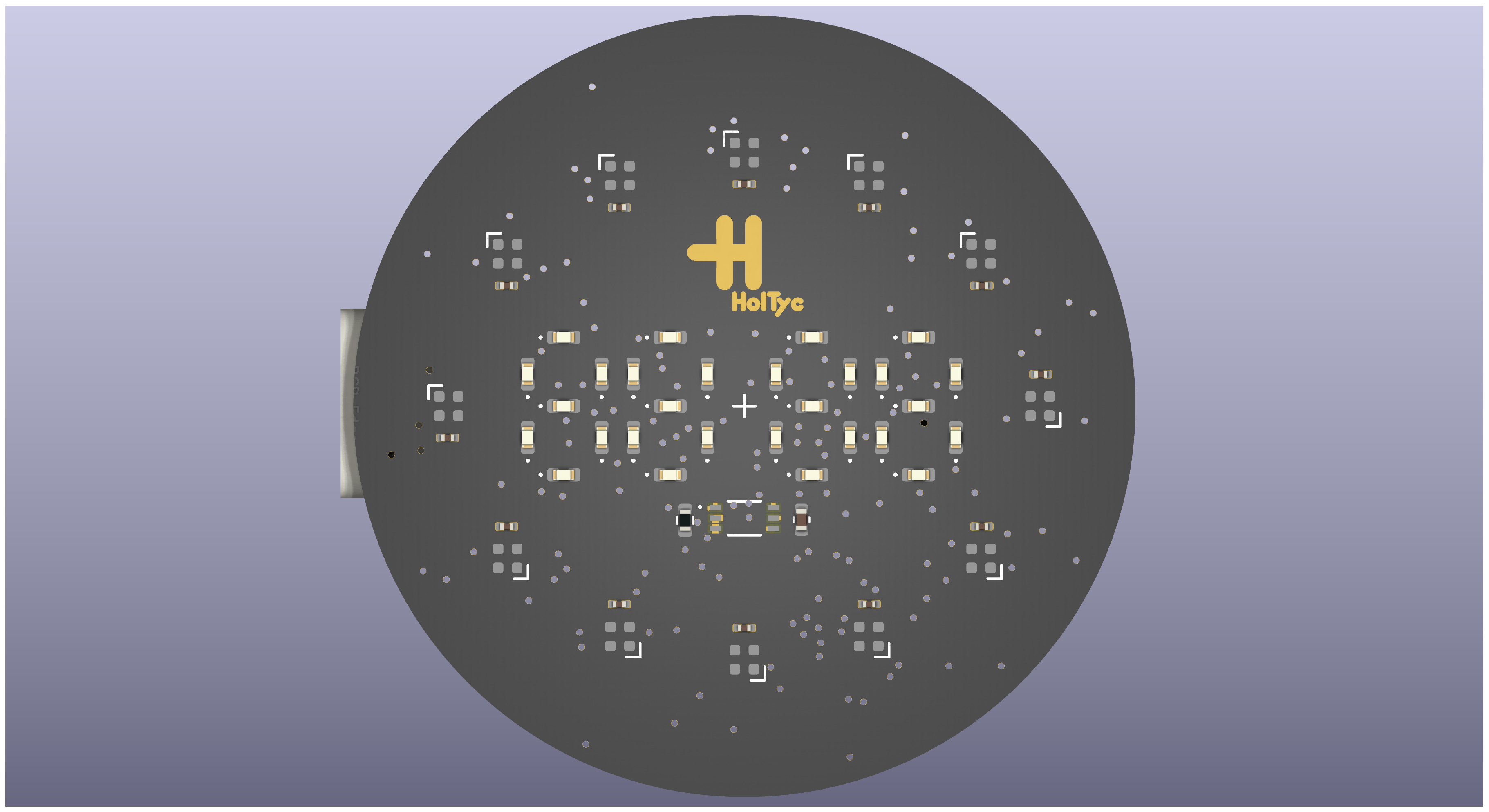 | 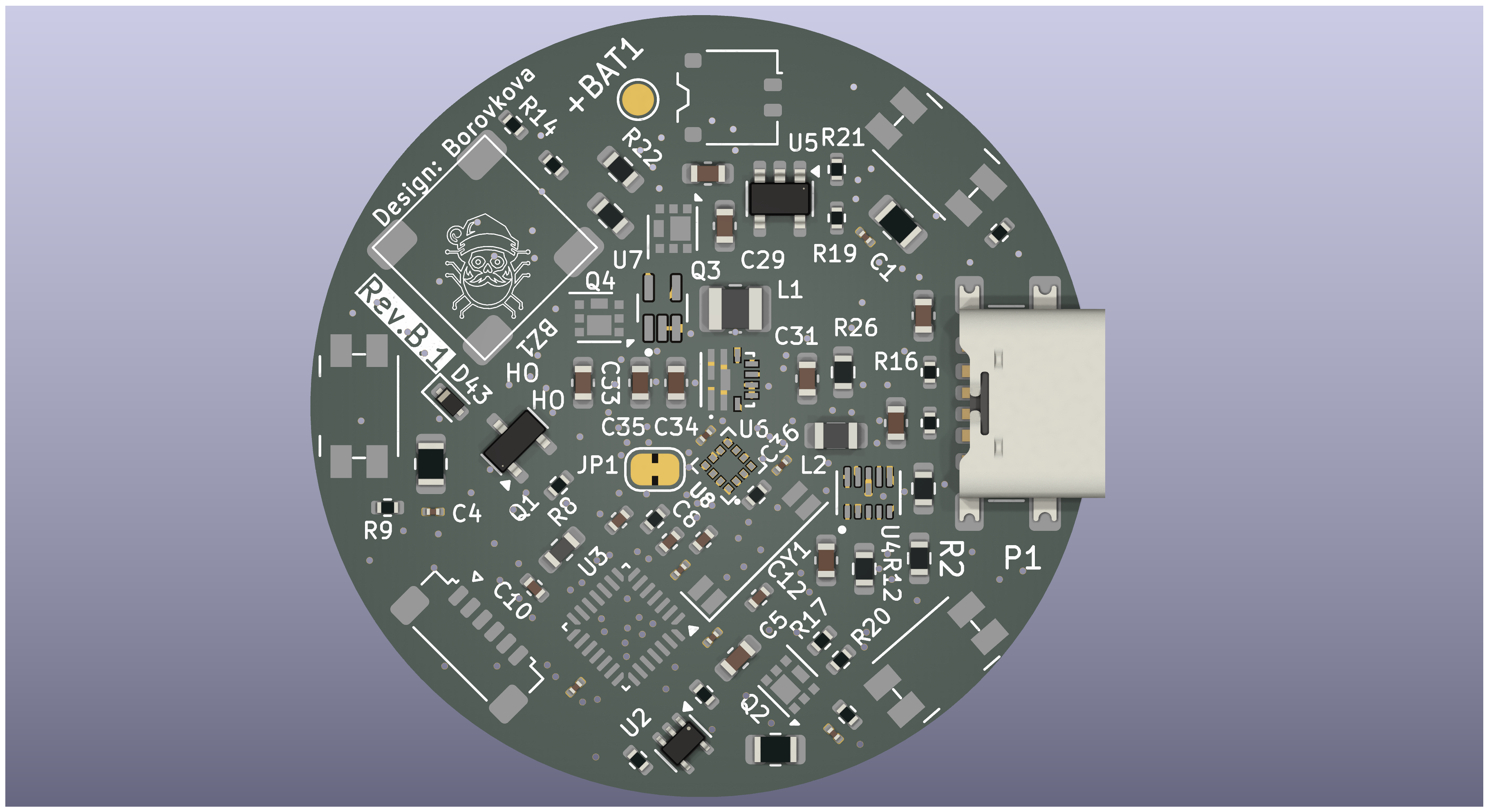 |
STM32_watch_NFC/
├── Firmware/               # STM32CubeIDE project (all firmware source code)
│   └── Core/
│       ├── Inc/            # Header files (main.h, BMA400.h, Din_LED.h, …)
│       └── Src/            # Source files (main.c, BMA400.c, Din_LED.c, …)
├── PCB/                    # KiCad project — schematic and PCB layout
│   └── STM32_watch_NFC/    # Main KiCad project files (.kicad_pcb, .kicad_sch, gerbers)
├── Firmware_old/           # Legacy firmware from earlier revisions (deprecated)
├── Datasheets_components/  # Datasheets for key ICs (STM32, BMA400, TPS63802, …)
├── HW_design/              # Hardware design notes and segment layout diagrams
├── Fotos/                  # PCB renders and design visuals
└── README.md| Component | Part | Notes |
|---|---|---|
| MCU | STM32L031G6U6 | Cortex-M0+, 32KB Flash, 8KB RAM |
| RGB LEDs | 12× WS2812B | Driven via TIM2 PWM + DMA |
| Display | Charlieplex matrix | 6 pins → 4-digit 7-segment (no external drivers) |
| Accelerometer | BMA400 | Wrist-wake via orientation interrupt |
| Light sensor | BH1750FVI | Auto-brightness (I2C) |
| Power converter | TPS63802 | Buck-boost regulator |
| RTC crystal | 32.768 kHz LSE | Accurate timekeeping in sleep |
| Buzzer | Passive | ~2.7 kHz tone |
The HH:MM display is built entirely with Charlieplexing — 6 GPIO pins control a 4-digit 7-segment matrix with no shift registers or external display drivers.
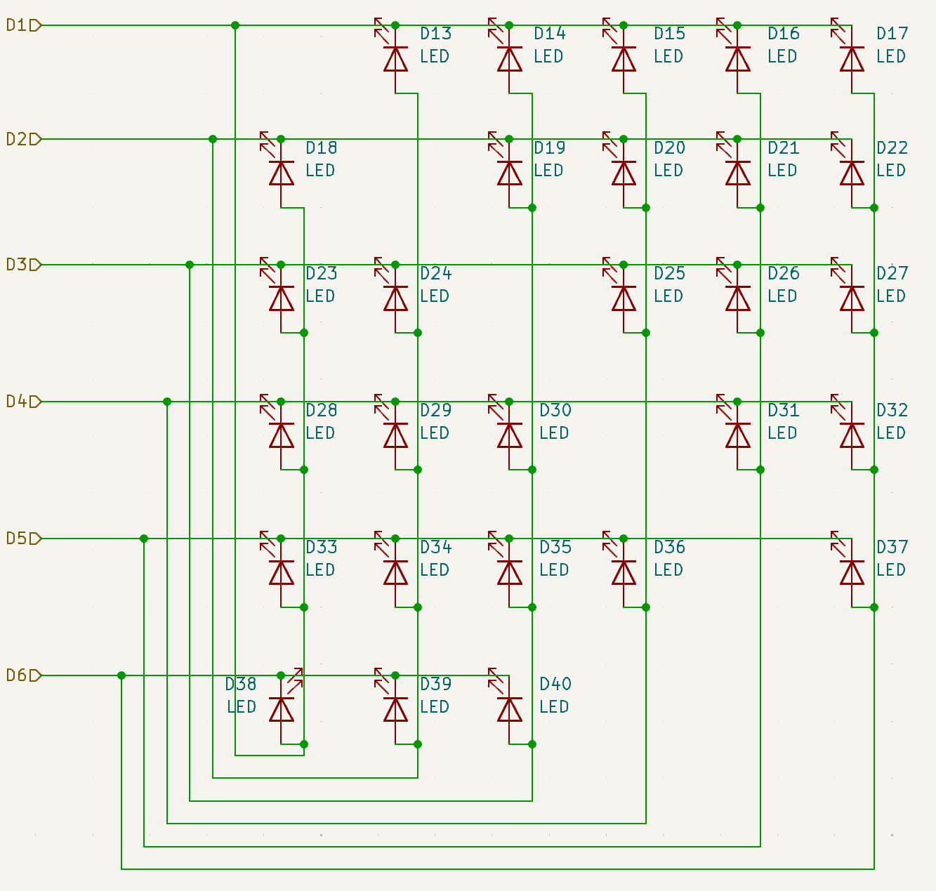
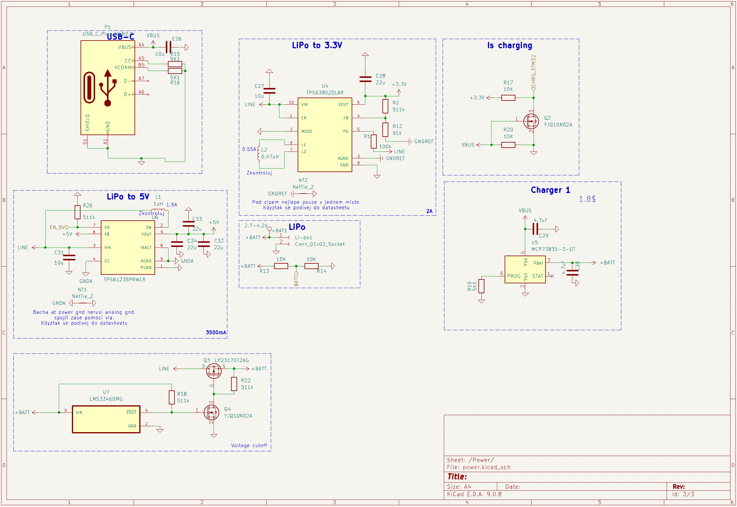
Note: The PCB had NFC hardware (ST25R3916B antenna area), but NFC functionality was scrapped during development. No NFC code exists in the firmware.
Firmware/ and select the project.Ctrl+B).Alternatively, flash the compiled .elf / .bin from Firmware/Debug/ using STM32CubeProgrammer.
changeTime mode.| Button | Short press | Long press (≥1 s) |
|---|---|---|
| Button_R | Show RGB analog clock | Enter time-set mode |
| Button_LT | Show digital clock | Enter charging display |
| Button_LB | Show digital clock | Cycle color theme |
| Button_R + Button_LB | Enter shooting game | — |
KiCad source files are in PCB/STM32_watch_NFC/. Gerber files ready for manufacturing are in PCB/STM32_watch_NFC/gerber/. A panelized version is available in PCB/Panelized_watch/.
MIT License
Copyright (c) 2025 HolTyc
Permission is hereby granted, free of charge, to any person obtaining a copy of this software and associated documentation files (the "Software"), to deal in the Software without restriction, including without limitation the rights to use, copy, modify, merge, publish, distribute, sublicense, and/or sell copies of the Software, and to permit persons to whom the Software is furnished to do so, subject to the following conditions:
The above copyright notice and this permission notice shall be included in all copies or substantial portions of the Software.
THE SOFTWARE IS PROVIDED "AS IS", WITHOUT WARRANTY OF ANY KIND, EXPRESS OR IMPLIED, INCLUDING BUT NOT LIMITED TO THE WARRANTIES OF MERCHANTABILITY, FITNESS FOR A PARTICULAR PURPOSE AND NONINFRINGEMENT. IN NO EVENT SHALL THE AUTHORS OR COPYRIGHT HOLDERS BE LIABLE FOR ANY CLAIM, DAMAGES OR OTHER LIABILITY, WHETHER IN AN ACTION OF CONTRACT, TORT OR OTHERWISE, ARISING FROM, OUT OF OR IN CONNECTION WITH THE SOFTWARE OR THE USE OR OTHER DEALINGS IN THE SOFTWARE.
| Qty | Value | Footprint | References |
|---|---|---|---|
| 56 | LED | LED_SMD:LED_0402_1005Metric | D13, D13, D14, D14, D15, D15, D16, D16, D17, D17, D18, D18, D19, D19, D20, D20 +40 |
| 48 | NPTH | NPTH | KiKit_MB_10_2, KiKit_MB_10_3, KiKit_MB_10_4, KiKit_MB_11_2, KiKit_MB_11_3, KiKit_MB_11_4, KiKit_MB_12_2, KiKit_MB_12_3, KiKit_MB_12_4, KiKit_MB_13_2, KiKit_MB_13_3, KiKit_MB_13_4, KiKit_MB_14_2, KiKit_MB_14_3, KiKit_MB_14_4, KiKit_MB_15_2 +32 |
| 40 | 100n | Capacitor_SMD:C_0201_0603Metric | C1, C1, C11, C11, C14, C14, C15, C15, C16, C16, C17, C17, C18, C18, C19, C19 +24 |
| 24 | SK6805 | LED_SMD:LED_SK6812_EC15_1.5x1.5mm | D1, D1, D2, D2, D3, D3, D4, D4, D5, D5, D10, D10, D11, D11, D12, D12 +8 |
| 10 | 10K | Resistor_SMD:R_0402_1005Metric | R10, R10, R13, R13, R14, R14, R17, R17, R20, R20 |
| 10 | 510 | Resistor_SMD:R_0402_1005Metric | R4, R4, R6, R6, R8, R8, R9, R9, R11, R11 |
| 8 | 10u | Capacitor_SMD:C_0603_1608Metric | C5, C5, C26, C26, C27, C27, C31, C31 |
| 8 | 22u | Capacitor_SMD:C_0603_1608Metric | C28, C28, C32, C32, C33, C33, C34, C34 |
| 8 | 511k | Resistor_SMD:R_0603_1608Metric | R2, R2, R18, R18, R22, R22, R26, R26 |
| 8 | Fiducial | Fiducial | KiKit_FID_B_1, KiKit_FID_B_2, KiKit_FID_B_3, KiKit_FID_B_4, KiKit_FID_T_1, KiKit_FID_T_2, KiKit_FID_T_3, KiKit_FID_T_4 |
| 6 | 16.5K | Resistor_SMD:R_0805_2012Metric | R3, R3, R5, R5, R7, R7 |
| 6 | 1u | Capacitor_SMD:C_0402_1005Metric | C2, C2, C9, C9, C10, C10 |
| 6 | 2.2K | Resistor_SMD:R_0402_1005Metric | R23, R23, R24, R24, R25, R25 |
| 6 | 5K1 | Resistor_SMD:R_0402_1005Metric | R15, R15, R16, R16, R19, R19 |
| 6 | SW_DPST_x2 | Button_Switch_SMD:Panasonic_EVQPUJ_EVQPUA | SW1, SW1, SW2, SW2, SW3, SW3 |
| 4 | 15pF | Capacitor_SMD:C_0402_1005Metric | C12, C12, C13, C13 |
| 4 | 4.7uF | Capacitor_SMD:C_0603_1608Metric | C29, C29, C30, C30 |
| 4 | NetTie_2 | NetTie:NetTie-2_SMD_Pad0.5mm | NT1, NT1, NT2, NT2 |
| 4 | YJQ10N02A | Package_DFN_QFN:Diodes_UDFN2020-6_Type-F | Q2, Q2, Q4, Q4 |
| 2 | 0.47uH | Inductor_SMD:L_0805_2012Metric | L2, L2 |
| 2 | 100k | Resistor_SMD:R_0603_1608Metric | R1, R1 |
| 2 | 10n | Capacitor_SMD:C_0402_1005Metric | C8, C8 |
| 2 | 1uH | Inductor_SMD:L_1008_2520Metric | L1, L1 |
| 2 | 2.7-4.2V | TestPoint:TestPoint_Pad_D1.5mm | +BAT1, +BAT1 |
| 2 | 32.768kHz | Crystal:Crystal_SMD_SeikoEpson_MC146-4Pin_6.7x1.5mm | Y1, Y1 |
| 2 | 74AHCT1G125 | Package_TO_SOT_SMD:SOT-353_SC-70-5 | U2, U2 |
| 2 | 91k | Resistor_SMD:R_0603_1608Metric | R12, R12 |
| 2 | BC817 | Package_TO_SOT_SMD:SOT-23 | Q1, Q1 |
| 2 | BH1750FVI-TR | BH1750FVI-TR:XDCR_BH1750FVI-TR | U1, U1 |
| 2 | BMA400 | BMA400:XDCR_BMA400 | U8, U8 |
| 2 | Buzzer | Buzzer_SMD:Buzzer_SMD | BZ1, BZ1 |
| 2 | Conn_01x02_Socket | Connector_Molex:Molex_Pico-EZmate_78171-0002_1x02-1MP_P1.20mm_Vertical | Li-po1, Li-po1 |
| 2 | Conn_01x06_Socket | Connector_JST:JST_SUR_SM06B-SURS-TF_1x06-1MP_P0.80mm_Horizontal | J1, J1 |
| 2 | D_Schottky | Diode_SMD:D_SOD-523 | D43, D43 |
| 2 | FerriteBead | Inductor_SMD:L_0603_1608Metric | FB1, FB1 |
| 2 | LMS33460MG | LMS33460MG:SOT65P210X110-5N | U7, U7 |
| 2 | LP2317DT2AG | Package_DFN_QFN:Diodes_UDFN2020-6_Type-F | Q3, Q3 |
| 2 | MCP73831-3-OT | Package_TO_SOT_SMD:SOT-23-5 | U5, U5 |
| 2 | STM32L031G6Ux | Package_DFN_QFN:QFN-28_4x4mm_P0.5mm | U3, U3 |
| 2 | SolderJumper_2_Bridged | Jumper:SolderJumper-2_P1.3mm_Bridged_RoundedPad1.0x1.5mm | JP1, JP1 |
| 2 | TPS61235PRWLR | TPS61235PRWLR:CONV_TPS61235PRWLR | U6, U6 |
| 2 | TPS63802DLAR | TPS63802DLAR:VREG_TPS63802DLAR | U4, U4 |
| 2 | USB_C_Plug_USB2.0 | Connector_USB:USB_C_Receptacle_GCT_USB4135-GF-A_6P_TopMnt_Horizontal | P1, P1 |
HolTyc/STM32_watch_NFC
Watch using STM32 with LED 7-segment display and RGB display


Studented0/universal-ai-terminal
A pocketable AI terminal that runs Claude Code and Ollama over LTE. Custom carrier board for a Raspberry Pi Compute Module 5, 7" AMOLED touchscreen, and its own cellular modem so it doesn't need WiFi.


ka1e27/dreams
Autonomous survey catamaran: CV-based obstacle avoidance, environmental sensing, and cellular telemetry to a web dashboard.

landjas09/Secure-Ready-Battery-Powered-Edge-Logger
Custom ESP32-C3 Secure-Ready Battery-Powered Edge Logger with environmental, light and acoustic sensing, local storage, DS3231 RTC, BQ27441 fuel gauging, SE050E2 secure element and TPS63802 buck-boost power.

Open-Smartwatch/open-smartwatch-gps
Hardware design files for the GPS version of the open-smartwatch


mjculross/Teensy-RV-Leveling-Helper
RV LEveling Helper using Teensy 4.0 + BMA400 Triple Axis Accelerometer Breakout + ILI9341 Color 320x240 TFT Touchscreen display
It measures 70 × 92 mm and has 4 copper layers, 1.6 mm thick.
314 parts, built around the 74AHCT1G125SE, BH1750FVI-TR, TPS61235PRWLR and TPS63802DLAR. The full list of its parts is on this page, with links to each part's symbol and footprint where PCBKit's library has them.
From the HolTyc/STM32_watch_NFC repository on GitHub, at the commit this page was made from: the board is PCB/Panelized_watch/Panelized_watch/Panelized_watch.kicad_pcb and its schematic PCB/Panelized_watch/Panelized_watch/Panelized_watch.kicad_sch. PCBKit opens the board in the browser, with nothing to install.
Its repository states no licence, so its author keeps all rights: ask HolTyc before reusing the design.