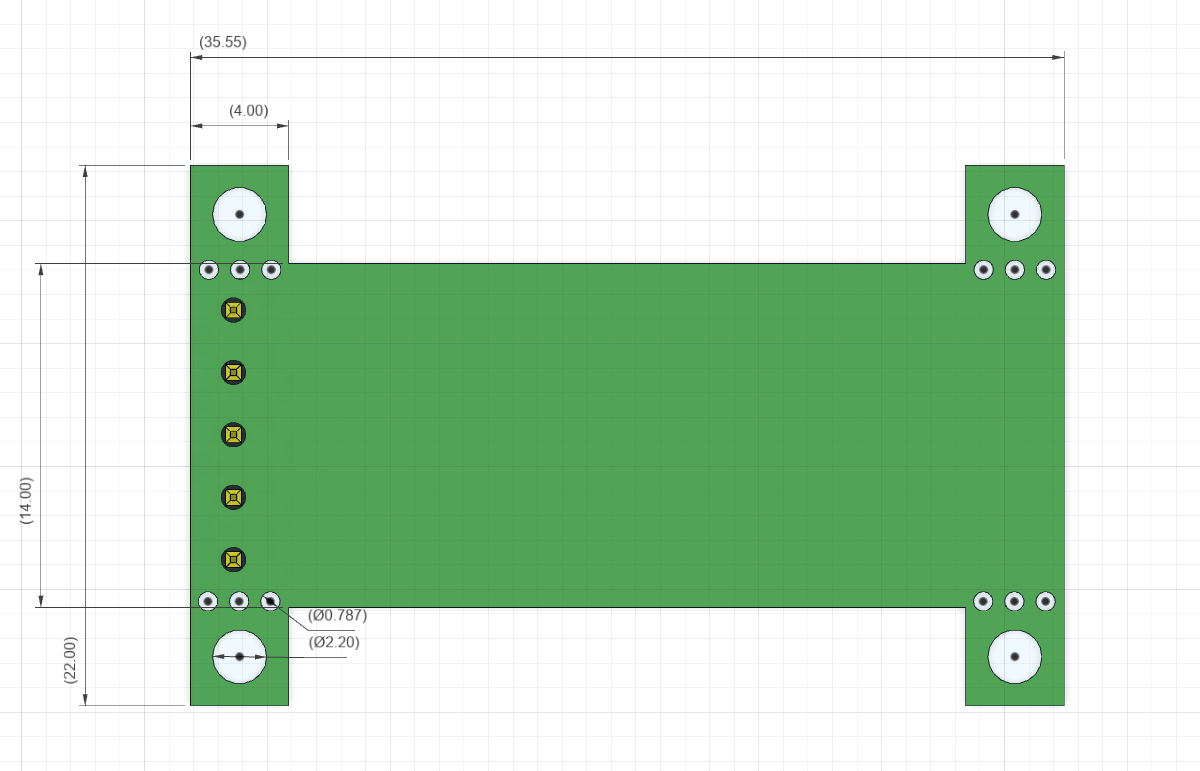
2 layers18.6 × 56.6 mm
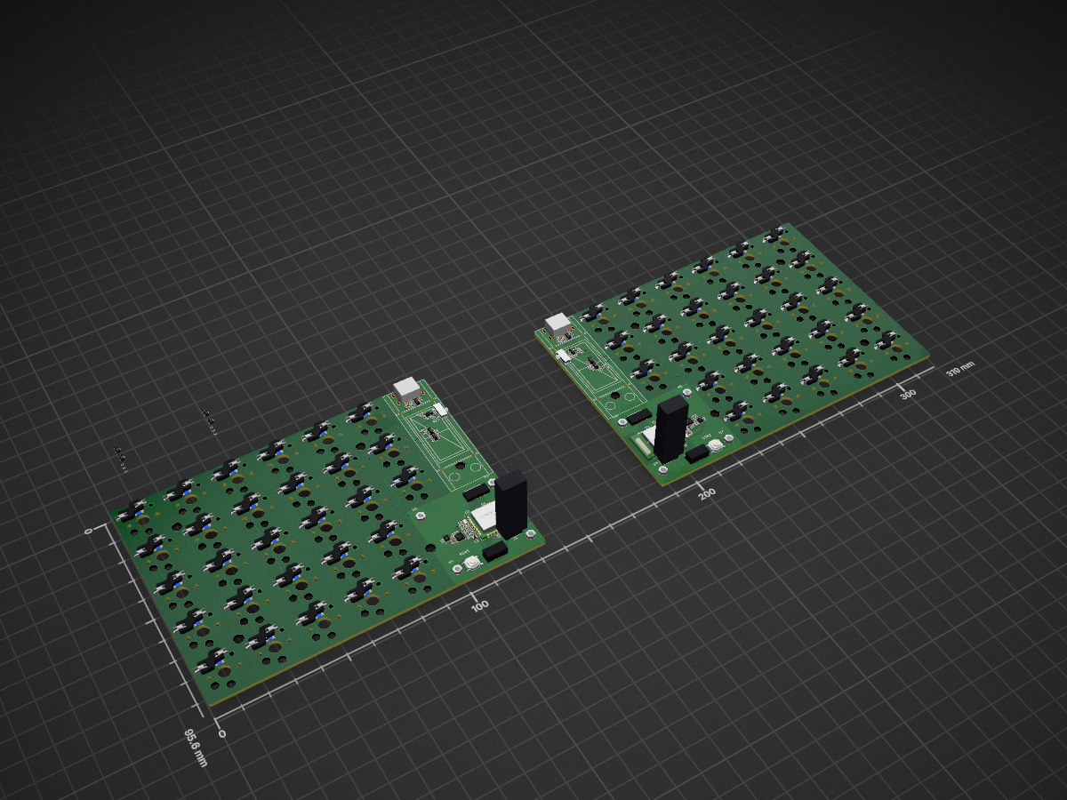
 Hob-dev/Orthus1
A highly portable split keyboard focused on feeling and sound.
Orthus is an open-source printed circuit board by Hob-dev, from the Hob-dev/Orthus repository on GitHub. It is a 2-layer board of 319 × 95.6 mm with 336 parts on 259 nets, routed with 2,034 tracks and 125 vias.
It is built around the BQ24075RGT, DW01A and FS8205, with the SRV05-4, AO3401A and BLM15PX121SN1D11 among its other parts. Its parts include 112 diodes, 76 capacitors, 56 switches, 34 resistors and 12 ICs. It belongs with the keyboards and input boards and the nRF52 and nRF5x boards of this library.


check nice-compat branch

check nice-compat-no-mount branch.


Since nice!view is released, in the future there will be more board designed for nice!view. so I redesign the pinout to be compatible with nice!view pinout, if in the future nice!view is run out of stock, mechkey folk will still have an alternative. DIY is sometimes more expensive, buy Nice!View instead of making this yourself https://nicekeyboards.com/nice-view
UPDATE: Nice!View Compat version is working, confirmed by some redditor, if your nice!view broken, you can replace it with this with the same config file as nice!view.
all of each version gerber, schematic and step files are here https://github.com/karnadii/sharp_memory_display_breakout/releases
I design it as small as possible with fewer component than the adafruit memory display using the datasheet and adafruit memory display as a guide. If you Mech Keyboards folk want to replace your i2c 128X32 OLED display, you just need to swap it and add bodge wire for the CLK pin to any available GPIO on your microcontroller. It is compatible with 128X32 OLED display pinout in mind. here is a comparison between nrfmicro (promicro size) and 128x32 oled display.

I intent to use this breakout as soldered or socketed using pin header or as a daughterboard. if using as a daughter-board don't solder the pin header and solder the jst connector. if soldered/socketed just solder the pin header and leave the jst connector, you can break the mounting hole if you want to save some space,the mountung hole is intended for using it as a daughter-board.
| Name | Qty | Value | Footprint | LCSC Part # |
|---|---|---|---|---|
| C1 | 1 | 560pF/680pF Unpolarized capacitor" | 0603 | C84721 |
| C2,C3 | 2 | 1uF Unpolarized capacitor | 0603 | C15849 |
| FB1,FB2 | 2 | Ferrite Bead | 0805 | C1017 |
| J2 | 1 | FH12-10S-0.5SH FPC Connector | - | C506791 |
| J3 | 1 | JST SH 5x1 (Optional) | - | https://www.aliexpress.com/item/1005003131441676.html |
| R1,R2,R3 | 3 | 10kΩ Resistor (optional) | 0603 | C25804 |
| LS011B7DH03 Display | 1 | - | - | https://aliexpress.com/item/1005001809102193.html |
Unfortunately there is only one person who sell LS011B7DH03 on aliexpress. If someone have another source than aliexpress, please tell me through issue. Also one out of 3 display I receive is dead. If you don't want to gamble wether you receive a good display or not, just buy nice!view
According to @Nicell the resistors is not required, you can remove all the resistor if you find it not needed. https://discord.com/channels/719497620560543766/1020985541598138388/1021185829491720302
everything is tested and work without problem.
5 PCBs with assembled component from JLPCB is $16 and 5 pcs LS011B7DH03 is $75 ($15x5), so for one LS011B7DH03 Sharp memory display it cost about $18.2 before shipping.
I think you can get cheaper if you order the components from aliexpress and solder all the components yourself and order from JLPCB the PCB only without assembly, probably $10 for PCB and component, $5 20 pcs PCB and another $5 for the components.
I found cheaper one from alibaba, a piece cost about $5. but I never order from alibaba. Maybe they require bigger minimum order for cheaper LCD.
or this one which is more cheaper but have different footprint for the socket, I believe this one intended to directly solder to PCB unlike this version that use socket for the display.
someone says that the price from alibaba is a fake price, if you message them, they will give you higher price.
Someone from China tell me the price for one LS011B7DH03 or similar memory display in china is 63 CNY ($8.97). So if you can obtain them from china, you can get maybe $12-$15 a piece for one working LS011B7DH03 breakout.
@nicell the maker of nice!nano released nice!view for $20 a piece.
Memory display is expensive, but with the battery saving feature of e-paper (~10μA power draw according to nicell) and high refresh rate 30hz, I think it is worth having it especially on one of your main wireless keyboards. At least have one for your main keyboard wether is DIY one like my breakout or nice!view.
I have test it with circuitpython, arduino and Zhepyr (ZMK) with nrfmicro, the test code is in test_code folder.
replacing my oled, need to bodge one wire, fortunately I have a lot of free gpio pins.

| Qty | Value | Footprint | References |
|---|---|---|---|
| 60 | 100n | Capacitor_SMD:C_0402_1005Metric | C1, C2, C11, C23, C31, C32, C33, C34, C35, C36, C37, C38, C39, C40, C41, C42 +44 |
| 56 | D_Small | Diode_SMD:D_SOD-123 | D1, D2, D10, D11, D12, D13, D14, D15, D16, D17, D18, D19, D20, D21, D22, D23 +40 |
| 56 | SW_PUSH | PCM_marbastlib-xp-choc:HOB_CHOC_V1&V2 | SW1, SW2, SW10, SW11, SW12, SW13, SW14, SW15, SW16, SW17, SW18, SW19, SW20, SW21, SW22, SW23 +40 |
| 56 | WS2812_2020 | kbd:YS-SK6812MINI-E | LED31, LED32, LED33, LED34, LED35, LED36, LED37, LED38, LED39, LED40, LED41, LED42, LED43, LED44, LED45, LED46 +40 |
| 12 | 10k | Resistor_SMD:R_0402_1005Metric | R4, R5, R6, R16, R20, R21, R23, R28, R33, R34, R40, R41 |
| 10 | 4u7 | Capacitor_SMD:C_0402_1005Metric | C6, C7, C8, C9, C10, C18, C19, C20, C21, C22 |
| 10 | MountingHole | Hobrary:SMD_BD5.6-L5.6-W5.6-D3.6 | H9, H10, H11, H12, H13, H14, H15, H16, H17, H18 |
| 8 | MountingHole | Hobrary:SMD-1_SMTSO1620MTJ | H1, H2, H3, H4, H5, H6, H7, H8 |
| 6 | 100R | Resistor_SMD:R_0402_1005Metric | R10, R15, R27, R29, R32, R39 |
| 4 | 12p | Capacitor_SMD:C_0402_1005Metric | C3, C4, C15, C16 |
| 4 | 1k5 | Resistor_SMD:R_0402_1005Metric | R2, R7, R19, R24 |
| 4 | 2N7002 | Package_TO_SOT_SMD:SOT-23 | Q1, Q2, Q31, Q33 |
| 4 | 5k1 | Resistor_SMD:R_0402_1005Metric | R35, R36, R37, R38 |
| 2 | 10 uH | Inductor_SMD:L_0603_1608Metric | L1, L3 |
| 2 | 100k | Resistor_SMD:R_0402_1005Metric | R17, R30 |
| 2 | 1k | Resistor_SMD:R_0402_1005Metric | R11, R31 |
| 2 | 1u | Capacitor_SMD:C_0402_1005Metric | C5, C17 |
| 2 | 2k | Resistor_SMD:R_0402_1005Metric | R3, R22 |
| 2 | 32.768 KHz | Crystal:Crystal_SMD_2012-2Pin_2.0x1.2mm | Y1, Y2 |
| 2 | 47k | Resistor_SMD:R_0402_1005Metric | R1, R18 |
| 2 | 750 mA | Fuse:Fuse_0603_1608Metric | F31, F32 |
| 2 | AO3401A | Package_TO_SOT_SMD:SOT-23 | Q32, Q34 |
| 2 | BLM15PX121SN1D | Inductor_SMD:L_0402_1005Metric | L31, L32 |
| 2 | BQ24075 | Package_DFN_QFN:VQFN-16-1EP_3x3mm_P0.5mm_EP1.6x1.6mm | U4, U9 |
| 2 | Battery | PCM_marbastlib-various:Molex_Pico-EZmate_78171-0002_1x02-1MP_P1.20mm_Vertical | J3, J7 |
| 2 | Conn_01x06 | Hobrary:FPC-SMD_6P-P0.50_XUNPU_FPC-05F-6PH15 | J31, J32 |
| 2 | Conn_01x07_Pin | Hobrary:FPC-SMD_8P-P0.50_XUNPU_FPC-05F-8PH15 | O1, O2 |
| 2 | DW01A | Package_TO_SOT_SMD:SOT-23-6 | U7, U12 |
| 2 | FS8205 | Package_TO_SOT_SMD:SOT-23-6 | U5, U10 |
| 2 | HRO_TYPE-C-31-M-14 | PCM_marbastlib-various:USB_C_Receptacle_HRO_TYPE-C-31-M-14 | J33, J34 |
| 2 | MAX17048 | Package_DFN_QFN:DFN-8-1EP_2x2mm_P0.5mm_EP0.6x1.2mm | U1, U3 |
| 2 | PWR | PCM_marbastlib-various:SW_MSK12C02-HB | BSW1, BSW2 |
| 2 | RSW_PUSH | Hobrary:SW-SMD_4P-L5.1-W5.1-P3.70-LS6.5-TL_H1.5 | RSW1, RSW2 |
| 2 | SRV05-4 | PCM_marbastlib-various:SOT-23-6-routable | U6, U11 |
| 2 | TC2030_SWD | PCM_marbastlib-various:CON_TC2030_outlined | J1, J4 |
| 2 | nRF52840_E73-2G4M08S1C | PCM_marbastlib-various:nRF52840_E73-2G4M08S1C | U2, U8 |


Hob-dev/Pockey
A play on the word "Pocket", this keyboard is meant to be ultra-portable ultra-low profile using Cherry ULP, with a magnetic enclosure mechanism that let's you fit the keyboard in your pocket.


It measures 319 × 95.6 mm and has 2 copper layers, 1.6 mm thick.
336 parts, built around the BQ24075RGT, DW01A, FS8205 and SRV05-4. The full list of its parts is on this page, with links to each part's symbol and footprint where PCBKit's library has them.
From the Hob-dev/Orthus repository on GitHub, at the commit this page was made from: the board is KiCad/Orthus.kicad_pcb and its schematic Components/OrthusSharp/OrthusSharp.kicad_sch. PCBKit opens the board in the browser, with nothing to install.
Its repository states no licence, so its author keeps all rights: ask Hob-dev before reusing the design.