4 layers73 × 98 mm
ALBERT FLIGHTCOMPUTER
felixznr/ALBERT
Albert I was a rhesus macaque monkey and the first mammal launched on a rocket (V-2 Rocket "Blossom No. 3") on June 18, 1948.
161 partsMIT

 GoTouchGra55/J.O.L.T1
12 degrees of freedom, 1 custom devboard, and 0 off-the-shelf solutions. JOLT is a quadruped robot built entirely from scratch.
JOLT V1 is an open-source printed circuit board by GoTouchGra55, from the GoTouchGra55/J.O.L.T repository on GitHub, published under the MIT licence. It is a 2-layer board of 71.8 × 48.5 mm with 73 parts on 98 nets, routed with 1,025 tracks and 191 vias.
It is built around the STM32F405RGT6, PCA9685BS and AMS1117-3.3, with the AMS1117-5.0, ICM-42688-P and SS14 among its other parts. Its parts include 23 capacitors, 13 resistors, 6 connectors, 5 ICs and 5 diodes. It belongs with the microcontroller boards and robots and motor control boards and the STM32 boards of this library.


JOLT (short for Joint Operated Legged Terrain walker) is my attempt at making a 12-DOF quadruped robot from scratch.
Yes, I designed a custom STM32-based dev board, CAD, and will implement custom firmware! :3
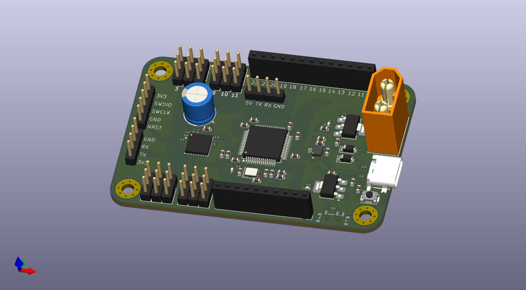
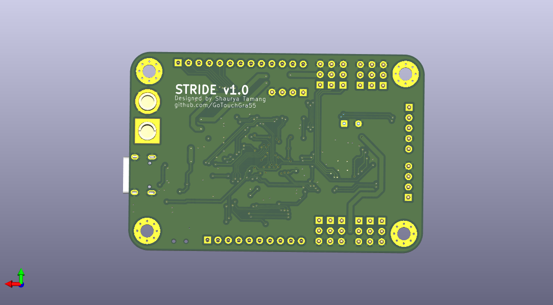
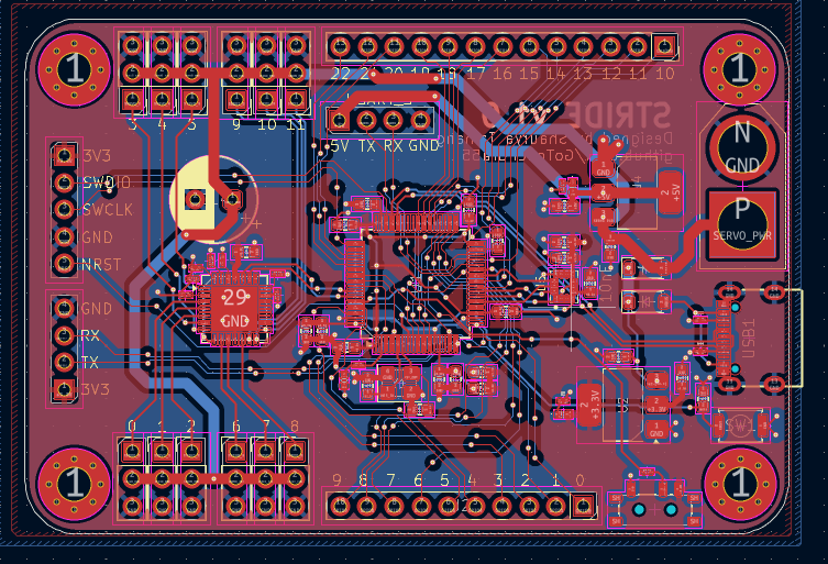
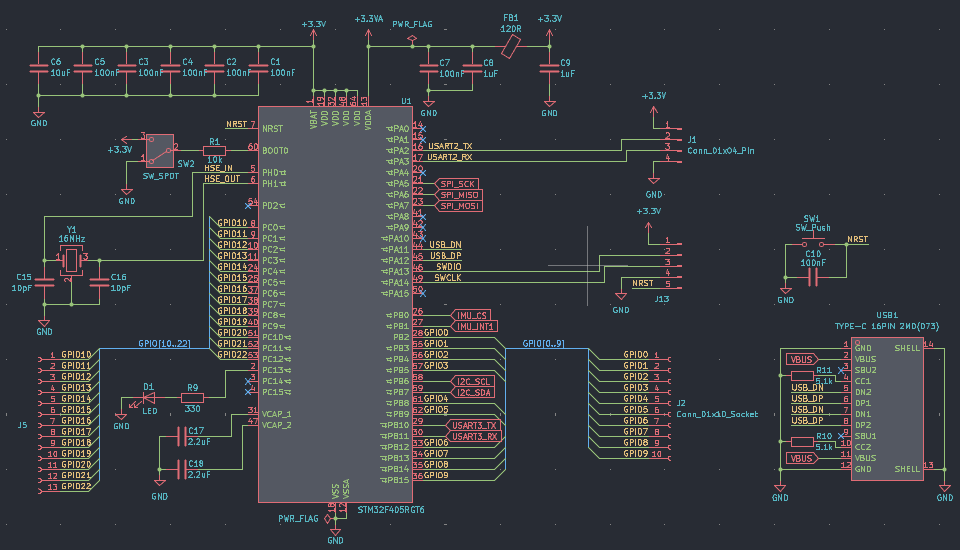
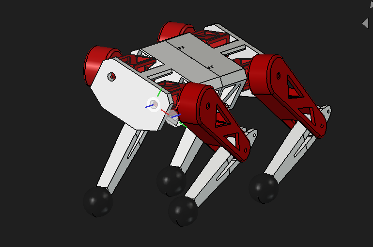
Btw you might be wondering why there are so many triangular cutouts in the design. Well first of all, it looks cool and secondly, I read an article about why triangles = strong. I won't bother explaining the physics here but, you can do your own research on why that is.
For those interested in the engineering principles, you can read more about why this geometry is superior for weight-to-strength ratios here: https://www.youtube.com/watch?v=Hn_iozUo9m4
.stl files can be found at
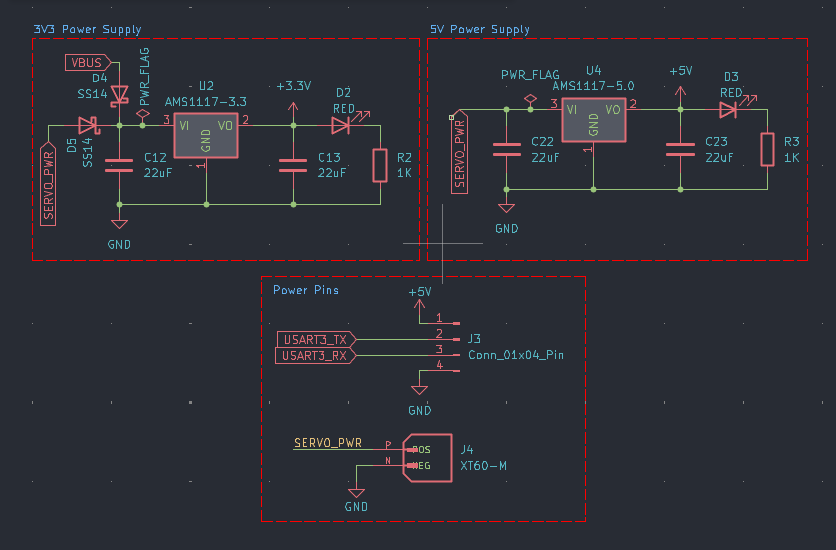
2s LiPo input (7.4V nominal voltage) is regulated to 5V and 3.3V rails for logic and peripherals.
Definitely don't use a higher cell lipo (unless you want to witness the magic smoke :p).
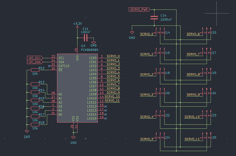
An STM32F405RGT6 MCU handles the math and motion control while a PCA9685 PWM servo controller chip controls all 12 servos across 4 legs.
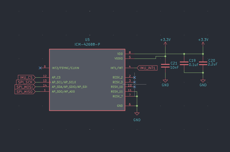
An onboard IMU provides orientation and motion feedback.
| Joint | Servo | Count |
|---|---|---|
| Hip yaw | MG996R | 4 |
| Hip pitch | MG996R | 4 |
| Knee | MG996R | 4 |
| Component | Part |
|---|---|
| MCU | STM32F405RGT6 |
| IMU | ICM42688-P |
| Servo Driver | PCA9685BS |
| Power | 5V + 3.3V LDO |
| Debug | ST-Link v2 |
| Input | XT-60 (2s LiPo) |
Unless you want a not so pleasant experience, I'd advise you to follow the order below:
In progress...
| Name | Purpose | Quantity | Total Cost (USD) | Distributor |
|---|---|---|---|---|
| Brass inserts | To secure the screws | 1 | 4.21 | Daraz Nepal |
| Metal Servo Horns | To connect servo with the linkages | 2 | 18.35 | Daraz Nepal |
| Bearings | To ensure smooth movement | 1 | 5.47 | Daraz Nepal |
| 0603 Resistors | Used in circuit | 1 | 4.58 | Daraz Nepal |
| Devboard PCB | The brains and the body of the quadruped | 1 | 135.41 | JLCPCB |
| Female Header Pins | For GPIO pins | 1 | 0.71 | Daraz Nepal |
| XT-60 Connector | To connect the battery to the board | 1 | 0.54 | Daraz Nepal |
| M4 Screws | To secure the components | 1 | 3.96 | Daraz Nepal |
| MG996R Servos | To move the joints of the robot | 12 | 41.08 | Daraz Nepal |
| Capacitor | Used in circuit | 1 | 0.65 | Daraz Nepal |
| Tweezers | To hold tiny 0201 components | 1 | 2.62 | Daraz Nepal |
| Solder Paste | For soldering | 1 | 4.26 | Daraz Nepal |
| Shipping | Shipping costs | 1 | 26.81 | Daraz Nepal + JLCPCB |
| Total | 248.65 |
MIT License - see LICENSE
Shaurya Tamang
GitHub: https://github.com/GoTouchGra55
Website: https://shauryatamang.netlify.app
| Qty | Value | Footprint | References |
|---|---|---|---|
| 12 | Conn_01x03_Pin | Connector_PinHeader_2.54mm:PinHeader_1x03_P2.54mm_Vertical | 0, 1, 2, 3, 4, 5, 6, 7, 8, 9, 10, 11 |
| 8 | 100nF | Capacitor_SMD:C_0603_1608Metric | C1, C2, C3, C4, C5, C7, C10, C11 |
| 8 | 10k | Resistor_SMD:R_0201_0603Metric | R1, R12, R13, R14, R15, R16, R17, R18 |
| 4 | 22uF | Capacitor_SMD:C_0603_1608Metric | C12, C13, C22, C23 |
| 4 | ~ | MountingHole:MountingHole_3.2mm_M3_Pad_Via | H1, H2, H3, H4 |
| 3 | 2.2uF | Capacitor_SMD:C_0603_1608Metric | C17, C18, C20 |
| 2 | 10pF | Capacitor_SMD:C_0603_1608Metric | C15, C16 |
| 2 | 1K | Resistor_SMD:R_0201_0603Metric | R2, R3 |
| 2 | 1uF | Capacitor_SMD:C_0603_1608Metric | C8, C9 |
| 2 | 5.1k | Resistor_SMD:R_0201_0603Metric | R10, R11 |
| 2 | Conn_01x04_Pin | Connector_PinHeader_2.54mm:PinHeader_1x04_P2.54mm_Vertical | J1, J3 |
| 2 | RED | LED_SMD:LED_0402_1005Metric | D2, D3 |
| 2 | SS14 | Diode_SMD:D_SOD-123 | D4, D5 |
| 1 | 0.1uF | Capacitor_SMD:C_0603_1608Metric | C19 |
| 1 | 10nF | Capacitor_SMD:C_0603_1608Metric | C21 |
| 1 | 10uF | Capacitor_SMD:C_0603_1608Metric | C6 |
| 1 | 120R | Inductor_SMD:L_0603_1608Metric | FB1 |
| 1 | 16MHz | Crystal:Crystal_SMD_3225-4Pin_3.2x2.5mm | Y1 |
| 1 | 2200uF | Capacitor_THT:CP_Radial_D8.0mm_P3.50mm | C14 |
| 1 | 330 | Resistor_SMD:R_0201_0603Metric | R9 |
| 1 | AMS1117-3.3 | Package_TO_SOT_SMD:SOT-223-3_TabPin2 | U2 |
| 1 | AMS1117-5.0 | Package_TO_SOT_SMD:SOT-223-3_TabPin2 | U4 |
| 1 | Conn_01x05_Pin | Connector_PinHeader_2.54mm:PinHeader_1x05_P2.54mm_Vertical | J13 |
| 1 | Conn_01x10_Socket | Connector_PinSocket_2.54mm:PinSocket_1x10_P2.54mm_Vertical | J2 |
| 1 | Conn_01x13_Socket | Connector_PinSocket_2.54mm:PinSocket_1x13_P2.54mm_Vertical | J5 |
| 1 | ICM-42688-P | Driver Footprint:PQFN50P300X250X97-14N | U5 |
| 1 | LED | LED_SMD:LED_0402_1005Metric | D1 |
| 1 | PCA9685BS | Package_DFN_QFN:QFN-28-1EP_6x6mm_P0.65mm_EP4.25x4.25mm | U3 |
| 1 | STM32F405RGT6 | Package_QFP:LQFP-64_10x10mm_P0.5mm | U1 |
| 1 | SW_Push | Button_Switch_SMD:SW_Push_SPST_NO_Alps_SKRK | SW1 |
| 1 | SW_SPDT | Button_Switch_SMD:SW_SPDT_Shouhan_MSK12C02 | SW2 |
| 1 | TYPE-C 16PIN 2MD(073) | lcsc:USB-C-SMD_TYPE-C-6PIN-2MD-073 | USB1 |
| 1 | XT60-M | footprint:AMASS_XT60-M | J4 |
felixznr/ALBERT
Albert I was a rhesus macaque monkey and the first mammal launched on a rocket (V-2 Rocket "Blossom No. 3") on June 18, 1948.

JoshCrouch/HEXCORE
HEXCORE is a Hexapod-type robot that includes both a custom remote as well as vision system making use of 2.4GHz RF and WiFi respectively.

Ben-Blair/Rocket-Build
Senior capstone project: demonstrate closed-loop lateral guidance of a high power rocket using forward canards, and handle the canard-wake-on-aft-fin interference problem correctly.

pms67/HadesFCS
Complete flight control system designed from scratch. Hardware designed with KiCad.

tadzio8425/Micromouse
Micromouse developed by the IEEE Robotics and Automation Society chapter of the Universidad de Los Andes, Bogotá (2023-2024).


ErdemA33/stm32f405-flight-controller
Open-source ArduPilot-compatible flight controller for fixed-wing UAVs. STM32F405, 4-layer KiCad design, built in 5 modular stages.

It measures 71.8 × 48.5 mm and has 2 copper layers, 1.6 mm thick.
73 parts, built around the STM32F405RGT6, PCA9685BS, AMS1117-3.3 and AMS1117-5.0. The full list of its parts is on this page, with links to each part's symbol and footprint where PCBKit's library has them.
From the GoTouchGra55/J.O.L.T repository on GitHub, at the commit this page was made from: the board is hardware/KiCAD_files/JOLT_V1.kicad_pcb and its schematic hardware/KiCAD_files/Board_Power.kicad_sch. PCBKit opens the board in the browser, with nothing to install.
Its repository publishes it under the MIT licence: you may reuse it on that licence's terms (keep the author's notice, and for a copyleft licence share your changes alike).