2 layers109 × 64 mm
Hyundai Dash V1.1
eymenyg/sim_dash
Download hyundaidashv1bng .zip from the Releases page and copy it to:
29 parts

 GSAS-LABS/P.003
Digital dice based on an ATtiny85 and 74HC595. Supports D4, D6, D8, and D10 modes, with configurable rolling animation, button-based type selection, EEPROM persistence, and low-power sleep mode for extended battery life.
P.003-V1.0.1 is an open-source printed circuit board by GSAS-LABS, from the GSAS-LABS/P.003 repository on GitHub, published under the CERN-OHL-S-2.0 licence. It is a 2-layer board of 42 × 78 mm with 21 parts on 30 nets, routed with 196 tracks and 21 vias.
It is built around the ATTINY85-20PU, 74HC595 and BS250. Its parts include 10 resistors, 3 switches, 2 ICs, 1 diode and 1 transistor. It belongs with the power boards and the AVR (ATmega, ATtiny) boards of this library.







Digital dice based on an ATtiny85 and 74HC595. Supports D4, D6, D8, and D10 modes, with configurable rolling animation, button-based type selection, EEPROM persistence, and low-power sleep mode for extended battery life.
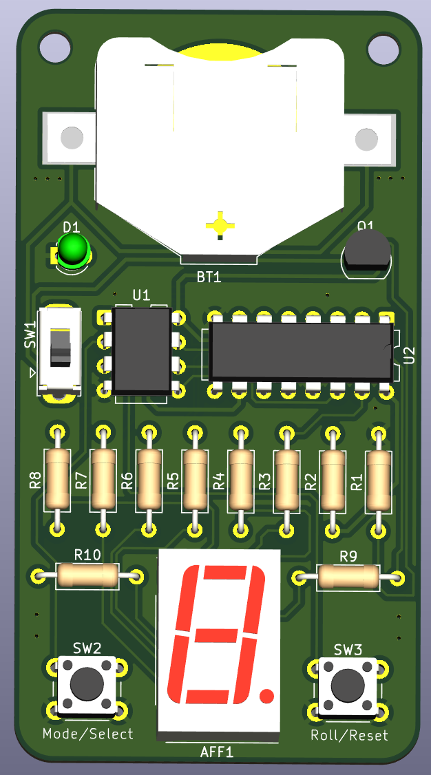
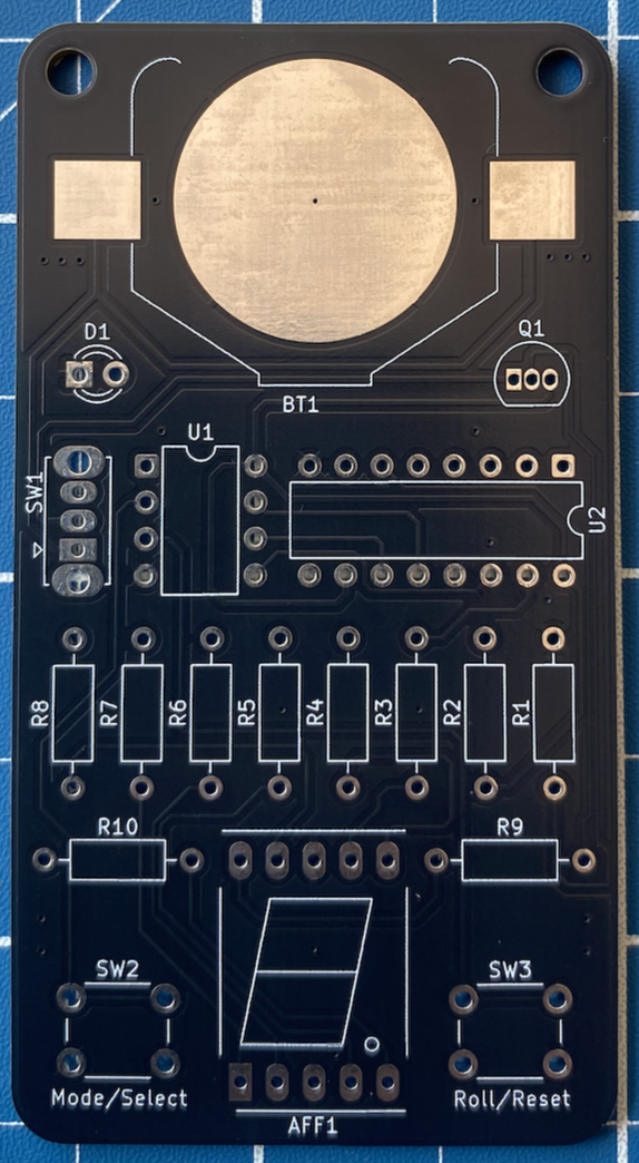
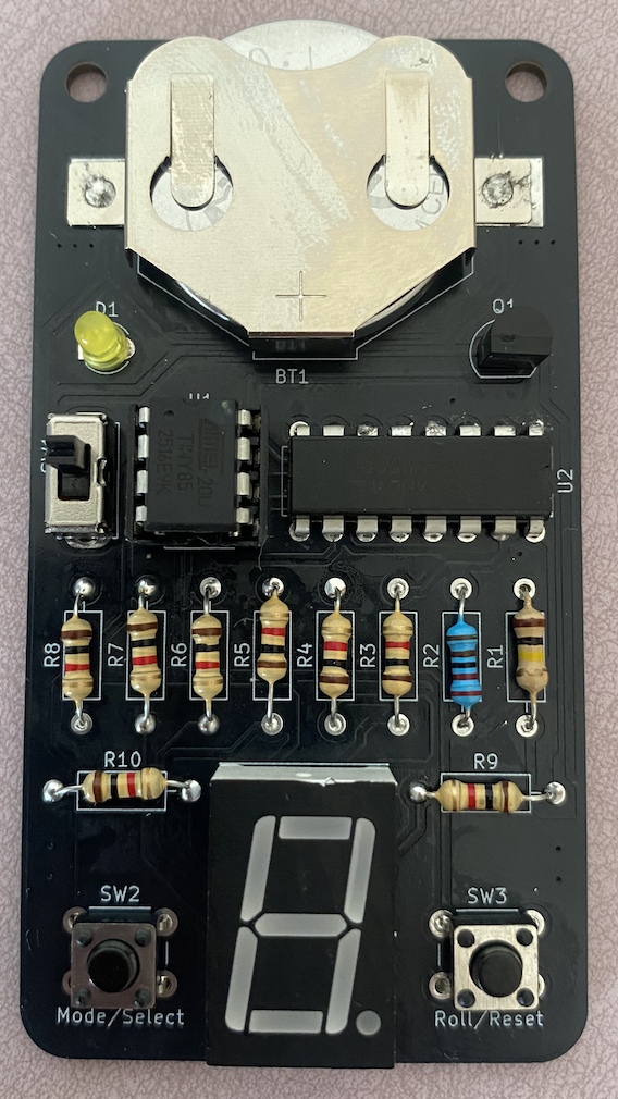
P.003 is a compact digital dice designed around the ATtiny85 microcontroller.
The project uses a 74HC595 shift register to control the display while minimizing the number of microcontroller pins required.
The dice supports multiple modes and remembers the selected configuration between power cycles.
The board includes an ON/OFF power switch.
Move the switch to the ON position to power the device.
When the board is powered, the power indicator LED turns on, indicating that the circuit is active and ready to use.
Move the switch to the OFF position when the device is not being used. Turning the board off helps preserve battery life.
A dedicated LED indicates the power status of the board.
For maximum battery life, turn the board off when it will not be used for an extended period.
The device includes two buttons:
Both buttons support short and long presses.
A short press rolls the currently selected dice.
The display performs the rolling animation and then shows the generated result.
A long press clears the display.
A short press changes the currently selected dice type.
The available dice types are:
D4 → D6 → D8 → D10A long press confirms the currently selected dice type.
While selecting a dice type, the led point (.) of the 7-segment display is illuminated to indicate that the device is in selection mode.
After confirming the selection with a long press, the decimal point turns off.
The confirmed dice type is remembered by the device and automatically restored the next time the board is powered on.
The device supports the following dice types:
| Mode | Possible Results |
|---|---|
| D4 | 1 to 4 |
| D6 | 1 to 6 |
| D8 | 1 to 8 |
| D10 | 0 to 9 |
In D10 mode, the generated values range from
0to9.
The board is powered by a CR2450 lithium coin cell.
Power consumption depends on the display state and whether the power indicator LED is installed.
| Operating State | Approx. Current |
|---|---|
| All 7-segment display segments ON | ~7.5 mA |
| Standby / Sleep — power indicator LED installed | ~0.65 mA |
| Standby / Sleep — power indicator LED not installed | ~0.05 mA |
The firmware uses the ATtiny85 Power-down sleep mode when the device is not being used. The ADC and unused peripherals are disabled during low-power operation to minimize battery consumption.
The power indicator LED is connected directly to the power circuit and therefore consumes approximately 0.60 mA continuously when the board is switched ON. This increases the standby consumption from approximately 0.05 mA to 0.65 mA.
For maximum battery life, omitting the power indicator LED significantly reduces the standby current.
Using a CR2450 with a nominal capacity of approximately 620 mAh:
| Operating State | Current | Theoretical Battery Life |
|---|---|---|
| Standby — LED installed | ~0.65 mA | ~954 hours / ~40 days |
| Standby — LED not installed | ~0.05 mA | ~517 days / ~1.42 years |
| All display segments ON continuously | ~7.5 mA | ~83 hours / ~3.4 days |
Battery life values are theoretical estimates based on the nominal 620 mAh battery capacity and measured current consumption. Actual battery life will be lower and depends on battery voltage, discharge characteristics, temperature, pulse loads, and the device's operating cycle.
The CR2450's rated capacity is specified under particular discharge conditions. Continuous operation at currents significantly above the manufacturer's standard drain can result in less usable capacity than the nominal 620 mAh rating.
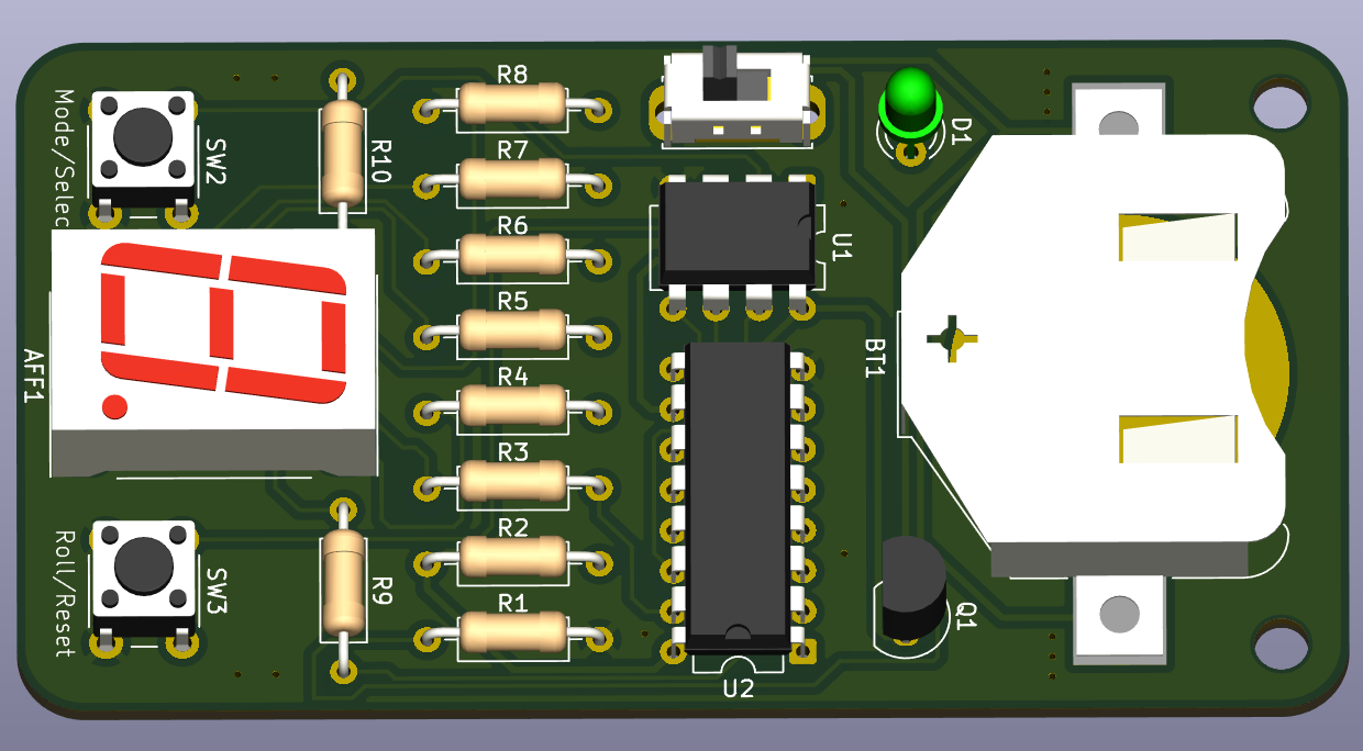
| Reference | Component | Value / Part | Quantity | Unit Price | Total |
|---|---|---|---|---|---|
| AFF1 | 7-Segment Display | Common Cathod | 1 | R$ 2.50 | R$ 2.50 |
| BT1 | Battery Holder | BAT-HLD-006-SMT, 1x CR2450 | 1 | R$ 2.53 | R$ 2.53 |
| D1 | LED | 3 mm Through-Hole LED | 1 | R$ 0.15 | R$ 0.15 |
| Q1 | P-Channel MOSFET | BS250 | 1 | R$ 2.50 | R$ 2.50 |
| R1 | Resistor | 100 kΩ | 1 | R$ 0.05 | R$ 0.05 |
| R2 | Resistor | 2.2 kΩ | 1 | R$ 0.05 | R$ 0.05 |
| R3–R10 | Resistor | 1K Ω | 8 | R$ 0.05 | R$ 0.40 |
| SW1 | Slide Switch | Micro Chave SS12D07 | 1 | R$ 0.50 | R$ 0.50 |
| SW2-SW3 | Push Button | 6 mm Tactile Switch | 2 | R$ 0.15 | R$ 0.30 |
| U1 | Microcontroller | ATTINY85-20PU, DIP-8 | 1 | R$ 26.00 | R$ 26.00 |
| U2 | Shift Register | SN74HC595N, DIP-16 | 1 | R$ 2.52 | R$ 2.52 |
| Item | Estimated Cost |
|---|---|
| Electronic Components | R$ 37.50 |
| PCB Manufacturing | R$ 8.50 |
| Estimated Total Project Cost | R$ 46 |
Component prices may vary depending on supplier, quantity, shipping costs, and location.
PCB manufacturing costs will be added once the board fabrication service and order quantity are defined.
The PCB uses custom routing values configured specifically for this project.
| Parameter | Dimension |
|---|---|
| Width | 42 mm |
| Height | 78 mm |
| Track Width | Recommended Use |
|---|---|
| 0.25 mm | Signal routing |
| 0.40 mm | Power and higher-current connections |
| Parameter | Value |
|---|---|
| Via Diameter | 0.8 mm |
| Drill Hole | 0.4 mm |
These values are configured as custom routing presets in the KiCad project and should be maintained when modifying or extending the PCB design.
The firmware is developed and built using PlatformIO.
The project includes a Makefile that simplifies the most common development tasks.
The project provides the following commands.
make installThis command checks whether PlatformIO is already installed.
If PlatformIO is not available, it installs PlatformIO using Homebrew.
make updateUpdates PlatformIO and prints the installed version.
make buildmake fusesmake uploadThe ATtiny85 is programmed using the ISP protocol.
The required signals are:
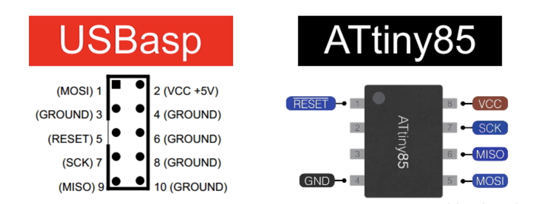
| Signal | Function |
|---|---|
| MOSI | Master Out Slave In |
| MISO | Master In Slave Out |
| SCK | Serial Clock |
| RESET | Programming Reset |
| VCC | Target Power |
| GND | Ground |
The board can be programmed using an ISP programmer such as a USBasp.
USBasp              ATtiny85 PCB

MOSI   ──────────── MOSI
MISO   ──────────── MISO
SCK    ──────────── SCK
RESET  ──────────── RESET
VCC    ──────────── VCC
GND ──────────── GNDGSAS-LABS is an independent engineering laboratory dedicated to the design, development, and exploration of electronics and software projects. It combines hardware and software engineering to create practical projects focused on embedded systems, microcontrollers, PCB design, and software development.
Areas of interest include:
This project combines software and hardware, with each part released under its corresponding open-source license.
The firmware is licensed under the GNU General Public License v3.0 (GPLv3).
The firmware can be used, studied, modified, and redistributed. Any distributed modifications must remain open-source and be released under the GPLv3.
The hardware design is licensed under the CERN Open Hardware Licence v2 (CERN-OHL-S).
This includes the hardware design files, such as:
The hardware design can be used, studied, modified, manufactured, and distributed. Hardware designs based on this project must preserve the same open and strongly reciprocal principles when distributed.
The GSAS-LABS name, logo, and visual identity are not covered by the software or hardware licenses.
All rights to the GSAS-LABS name and logo are reserved by their respective owner.
Use of the GSAS-LABS name or logo does not imply endorsement, affiliation, or approval of derivative projects.
Experiment · Build · Learn · Share
Made with ❤️ by GSAS-LABS
| Qty | Value | Footprint | References |
|---|---|---|---|
| 8 | 1K | Resistor_THT:R_Axial_DIN0207_L6.3mm_D2.5mm_P10.16mm_Horizontal | R3, R4, R5, R6, R7, R8, R9, R10 |
| 2 | MountingHole_3.2mm_M3 | MountingHole:MountingHole_3.2mm_M3 | , |
| 1 | 100K | Resistor_THT:R_Axial_DIN0207_L6.3mm_D2.5mm_P10.16mm_Horizontal | R1 |
| 1 | 2.2K | Resistor_THT:R_Axial_DIN0207_L6.3mm_D2.5mm_P10.16mm_Horizontal | R2 |
| 1 | 3V | Battery:BatteryHolder_Keystone_3008_1x2450 | BT1 |
| 1 | 74HC595 | Package_DIP:DIP-16_W7.62mm | U2 |
| 1 | ATtiny85-20P | Package_DIP:DIP-8_W7.62mm | U1 |
| 1 | BS250 | Package_TO_SOT_THT:TO-92_Inline | Q1 |
| 1 | Display | Display_7Segment:7SegmentLED_LTS6760_LTS6780 | AFF1 |
| 1 | LED | LED_THT:LED_D3.0mm | D1 |
| 1 | Mode | Button_Switch_THT:SW_PUSH_6mm_H4.3mm | SW2 |
| 1 | ON/OFF | Button_Switch_THT:SW_Slide_SPDT_Straight_CK_OS102011MS2Q | SW1 |
| 1 | Roll | Button_Switch_THT:SW_PUSH_6mm_H4.3mm | SW3 |
eymenyg/sim_dash
Download hyundaidashv1bng .zip from the Releases page and copy it to:


tibordp/coffee-timer
Kitchen timer on an ATtiny85 with a 7-segment display and a couple of shift registers


E-anae/HelioHeat-PCB
Cette section présente l'architecture d'un thermomètre autonome fonctionnant à l'aide d'un panneau solaire. L'objectif est de mesurer la température d'un lieu et d'afficher sur des afficheurs 7 segments tout en assurant…

Plasmarobo/Disarmed
Heavily inspired by Keep Talking and Nobody Explodes and Bomb Corp.
It measures 42 × 78 mm and has 2 copper layers, 1.6 mm thick.
21 parts, built around the ATTINY85-20PU, 74HC595 and BS250. The full list of its parts is on this page, with links to each part's symbol and footprint where PCBKit's library has them.
From the GSAS-LABS/P.003 repository on GitHub, at the commit this page was made from: the board is P.003-V1.0.1/P.003-V1.0.1.kicad_pcb and its schematic P.003-V1.0.1/7_segment_display.kicad_sch. PCBKit opens the board in the browser, with nothing to install.
Its repository publishes it under the CERN-OHL-S-2.0 licence: you may reuse it on that licence's terms (keep the author's notice, and for a copyleft licence share your changes alike).