
2 layers33.3 × 38 mm
ESP32-C3-WROOM02 dev board
pushtiujeniya/ESP32-C3-WROOM02_dev-board
This project is a custom 2-layer development board designed around the ESP32-C3-WROOM-02 Wi‑Fi + Bluetooth MCU module.
30 parts2

 FrancoSpitale/c3-pico
Minimalist ESP32-C3 dev board — USB-C native USB, no UART bridge. KiCad 9, WIP (schematic ERC-clean).
C3-pico is an open-source printed circuit board by FrancoSpitale, from the FrancoSpitale/c3-pico repository on GitHub, published under the MIT licence. It is a 2-layer board of 28.4 × 51.5 mm with 21 parts on 28 nets, routed with 251 tracks and 22 vias.
It is built around the ESP32-C3-WROOM-02-H4, AP2112K-3.3 and USBLC6-2SC6. Its parts include 6 resistors, 5 capacitors, 3 ICs, 3 connectors and 2 diodes. It belongs with the microcontroller boards and interfaces and adapters boards and the ESP32 and RISC-V boards of this library.


A no-frills ESP32-C3 development board in KiCad 9: USB-C with native USB, 3.3 V LDO, BOOT/RESET buttons and every usable GPIO on two breadboard-friendly 0.1" rows. Designed to be the board you actually reach for — nothing on it that a blinky-to-production bring-up doesn't need.
| Top | Bottom |
|---|---|
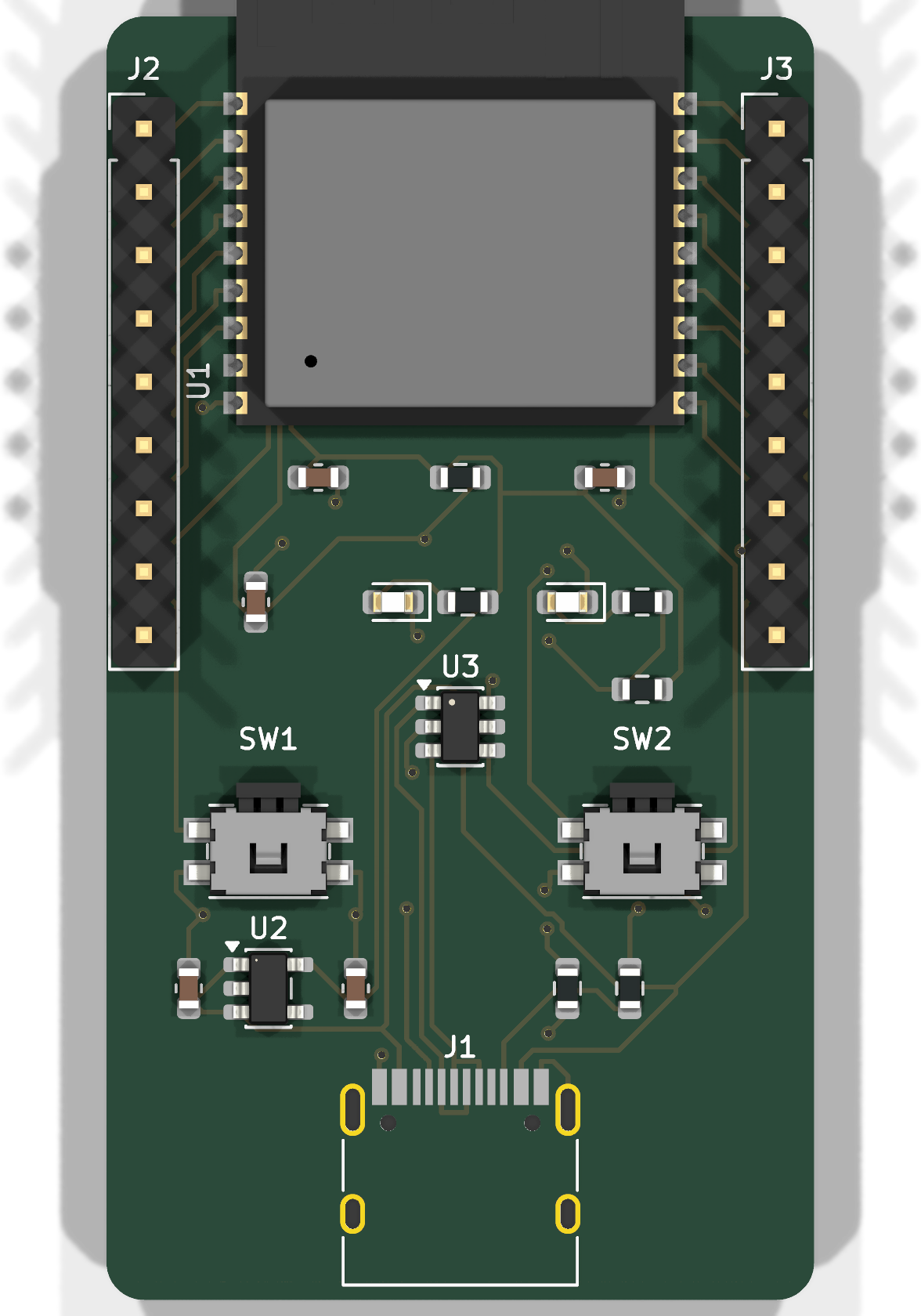 | 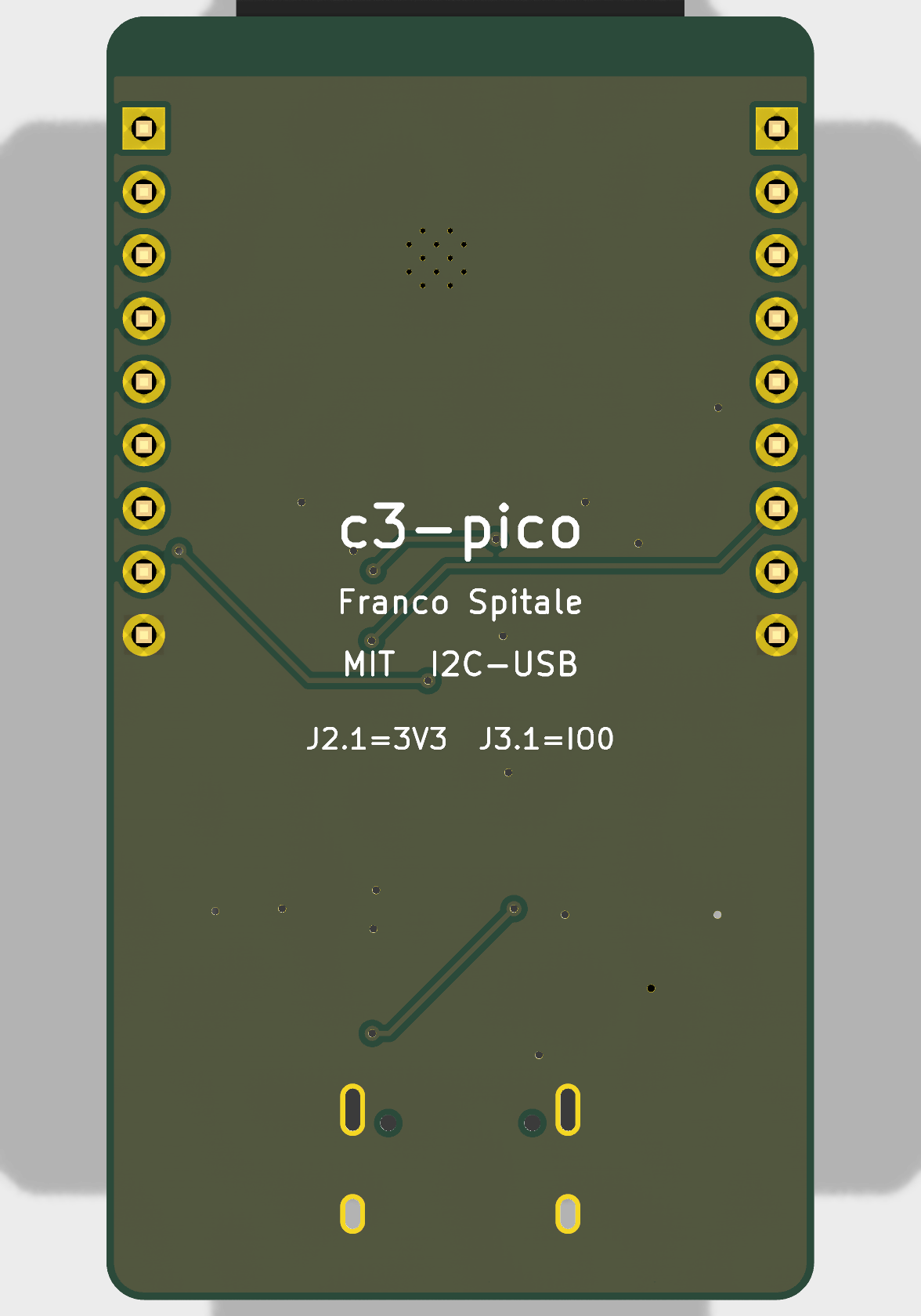 |
Schematic: docs/schematic.svg · Source: hardware/
| MCU | ESP32-C3-WROOM-02-N4 (RIS-V, Wi-Fi + BLE, 4 MB flash) |
| USB | USB-C, native USB-Serial-JTAG (no bridge IC) |
| Power | USB 5 V → AP2112K-3.3 LDO (600 mA) |
| I/O | 13 GPIO on 2 × 1×9 headers, 1.0" apart (breadboard) |
| Board | 28.4 × 51.5 mm, 2-layer, 1.6 mm FR-4 |
| Buttons | BOOT (IO9) + RESET (EN) |
| LEDs | power (green) + user (IO8, blue) |
Module, not chip-down. ESP32-C3-WROOM-02 (PCB antenna, pre-certified RF) instead of a bare ESP32-C3 with discrete RF. On a hobby/prototyping board the ~US$1 premium buys you regulatory-certified radio and zero antenna-matching risk on a 2-layer board — chip-down C3 designs want controlled impedance and a tuned pi network that this class of board can't justify.
Native USB only, UART on the header. The C3's built-in USB-Serial-JTAG (GPIO18/19) goes straight to the USB-C connector — no CP2102/CH340, which removes a BOM line, a failure mode, and ~US$0.50. GPIO18/19 are therefore not on the headers; UART0 (IO20/IO21) is, for classic serial workflows and as the escape hatch if an application reconfigures the USB pins.
USB-C done by the spec. 5.1 k pulldowns on CC1/CC2 mark the board as a UFP device, so it powers up from USB-C hosts and C-to-C cables/chargers (boards that skip these only work on A-to-C cables). USBLC6-2SC6 ESD array on D+/D−.
Strapping pins handled, not hidden. IO9 (BOOT) has its button; IO8 gets a 10 k pull-up (required high for serial download mode) and doubles as the user LED, Espressif-devkit style. Both are still broken out — the pull-up is weak enough to ignore in normal use.
EN with RC delay. 10 k pull-up + 1 µF on EN gives a clean power-on ramp and a proper RESET button without a supervisor chip.
Antenna overhang + bottom ground plane. The module hangs off the top edge so its PCB antenna clears the board copper (with a copper keep-out under the antenna footprint as a belt-and-suspenders measure). The stackup is the classic 2-layer arrangement — signals and power on top, an unbroken ground plane on the bottom — so every top trace has a clean return path directly beneath it.
| Left (J2) | Right (J3) |
|---|---|
| 3V3 | IO0 |
| EN | IO1 |
| IO4 | IO2 |
| IO5 | IO3 |
| IO6 | IO21 (TX) |
| IO7 | IO20 (RX) |
| IO8 (LED) | IO10 |
| IO9 (BOOT) | 5V |
| GND | GND |
Header order mirrors the module's physical pin order, so the layout fans out 1:1 with no crossings.
fabrication/c3-pico-gerbers-jlcpcb.zip uploads directly to JLCPCB: 2 layers,
1.6 mm, ENIG recommended (fine-pitch module pads). c3-pico-bom.csv and
c3-pico-pos.csv are ready for the assembly service — add LCSC part numbers at
order time. The module and USB-C are the only fine-pitch parts; everything else
is 0603 or SOT-23.
hardware/     KiCad 9 project (schematic, PCB, ERC/DRC reports)
fabrication/  Gerbers zip (JLCPCB), BOM, pick & place
docs/ Renders and schematic SVGMIT — see LICENSE. Hardware provided as-is, no warranty; review before fabricating. Not yet fabricated — if you build one, open an issue with results.
Franco Spitale, 2026. Rev 1.0.
| Qty | Value | Footprint | References |
|---|---|---|---|
| 3 | 1uF | Capacitor_SMD:C_0603_1608Metric | C3, C4, C5 |
| 2 | 10k | Resistor_SMD:R_0603_1608Metric | R1, R7 |
| 2 | 1k | Resistor_SMD:R_0603_1608Metric | R5, R6 |
| 2 | 1x09_Header | Connector_PinHeader_2.54mm:PinHeader_1x09_P2.54mm_Vertical | J2, J3 |
| 2 | 5k1 | Resistor_SMD:R_0603_1608Metric | R3, R4 |
| 1 | 100nF | Capacitor_SMD:C_0603_1608Metric | C1 |
| 1 | 10uF | Capacitor_SMD:C_0603_1608Metric | C2 |
| 1 | AP2112K-3.3 | Package_TO_SOT_SMD:SOT-23-5 | U2 |
| 1 | BOOT | Button_Switch_SMD:Panasonic_EVQPUJ_EVQPUA | SW1 |
| 1 | ESP32-C3-WROOM-02 | RF_Module:ESP32-C3-WROOM-02 | U1 |
| 1 | RESET | Button_Switch_SMD:Panasonic_EVQPUJ_EVQPUA | SW2 |
| 1 | USB-C | Connector_USB:USB_C_Receptacle_HRO_TYPE-C-31-M-12 | J1 |
| 1 | USBLC6-2SC6 | Package_TO_SOT_SMD:SOT-23-6 | U3 |
| 1 | blue | LED_SMD:LED_0603_1608Metric | LED2 |
| 1 | green | LED_SMD:LED_0603_1608Metric | LED1 |
pushtiujeniya/ESP32-C3-WROOM02_dev-board
This project is a custom 2-layer development board designed around the ESP32-C3-WROOM-02 Wi‑Fi + Bluetooth MCU module.


anasskrim61-wq/esp32-c3-mini
Custom ESP32-C3 Mini IoT hardware design and KiCad PCB project

bapsenpai-blip/STM32F405-4-layer-flight-controller
My first PCB revision, not fabricated yet, looking for design review


NozomiNetworks/NN-antenna-manager
Open source project for a custom antenna manager for SDR cards

aayanrahman/Star-Notifier
Star-shaped USB-C ESP32-C3 board that lights up when Claude or Cursor is done

Akshath2002/ESP32-Mini-Evaluation-Board
A compact 4-layer ESP32 evaluation board designed in KiCad, focused on reliable power distribution, signal integrity, and ease of prototyping.
It measures 28.4 × 51.5 mm and has 2 copper layers, 1.6 mm thick.
21 parts, built around the ESP32-C3-WROOM-02-H4, AP2112K-3.3 and USBLC6-2SC6. The full list of its parts is on this page, with links to each part's symbol and footprint where PCBKit's library has them.
From the FrancoSpitale/c3-pico repository on GitHub, at the commit this page was made from: the board is hardware/c3-pico.kicad_pcb and its schematic hardware/c3-pico.kicad_sch. PCBKit opens the board in the browser, with nothing to install.
Its repository publishes it under the MIT licence: you may reuse it on that licence's terms (keep the author's notice, and for a copyleft licence share your changes alike).