2 layers101.6 × 53.3 mm
 ElektroNeo/Adjustable-Wireless-Neuro-Stimulator-System5
🧠 0-5.5mA adjustable wireless neurostimulator system made with PIC16F1713 and App Inventor.
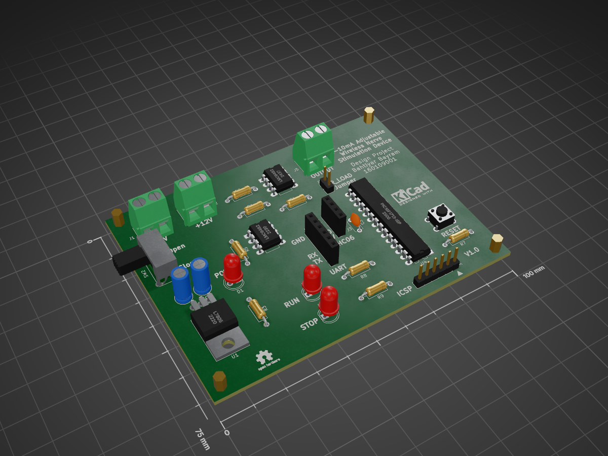
Adjustable Wireless Neuro Stimulator System is an open-source printed circuit board by ElektroNeo, from the ElektroNeo/Adjustable-Wireless-Neuro-Stimulator-System repository on GitHub, published under the GPL-3.0 licence. It is a 2-layer board of 100 × 75 mm with 33 parts on 43 nets, routed with 222 tracks and 0 vias.
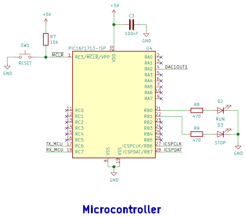
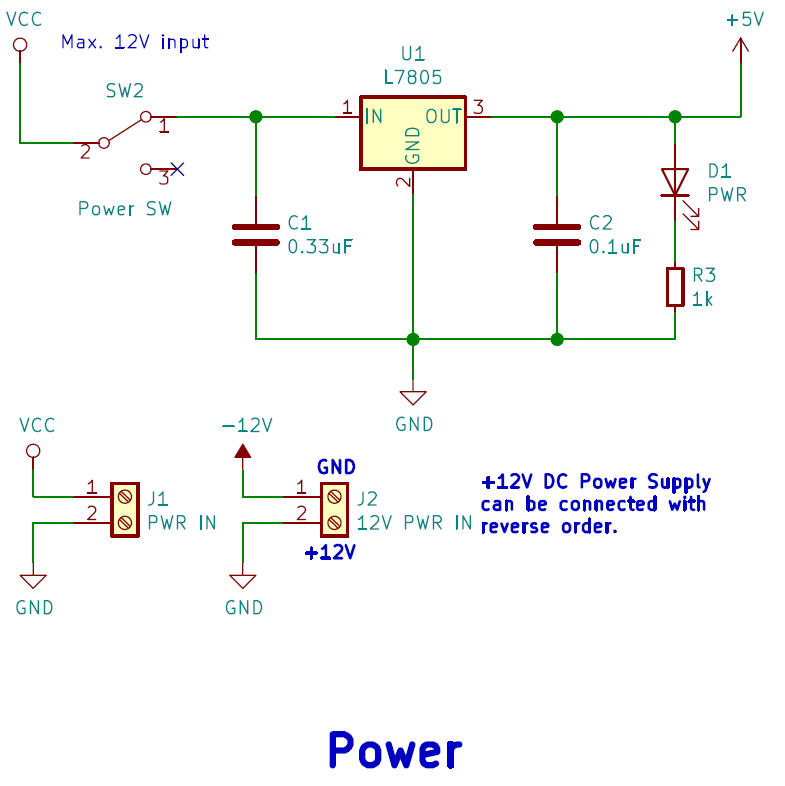
It is built around the LMC6482IN and L7805. Its parts include 8 resistors, 6 connectors, 4 ICs, 3 capacitors and 3 diodes. It belongs with the PIC boards of this library.


This project is made for the Design Project lecture. With this system, you can control output current by using Android application which made with App Inventor.
In the software used PIC16F1713 microcontroller features listed below.
| Disconnected App | Connected App |
|---|---|
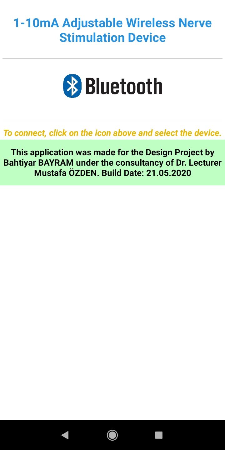 | 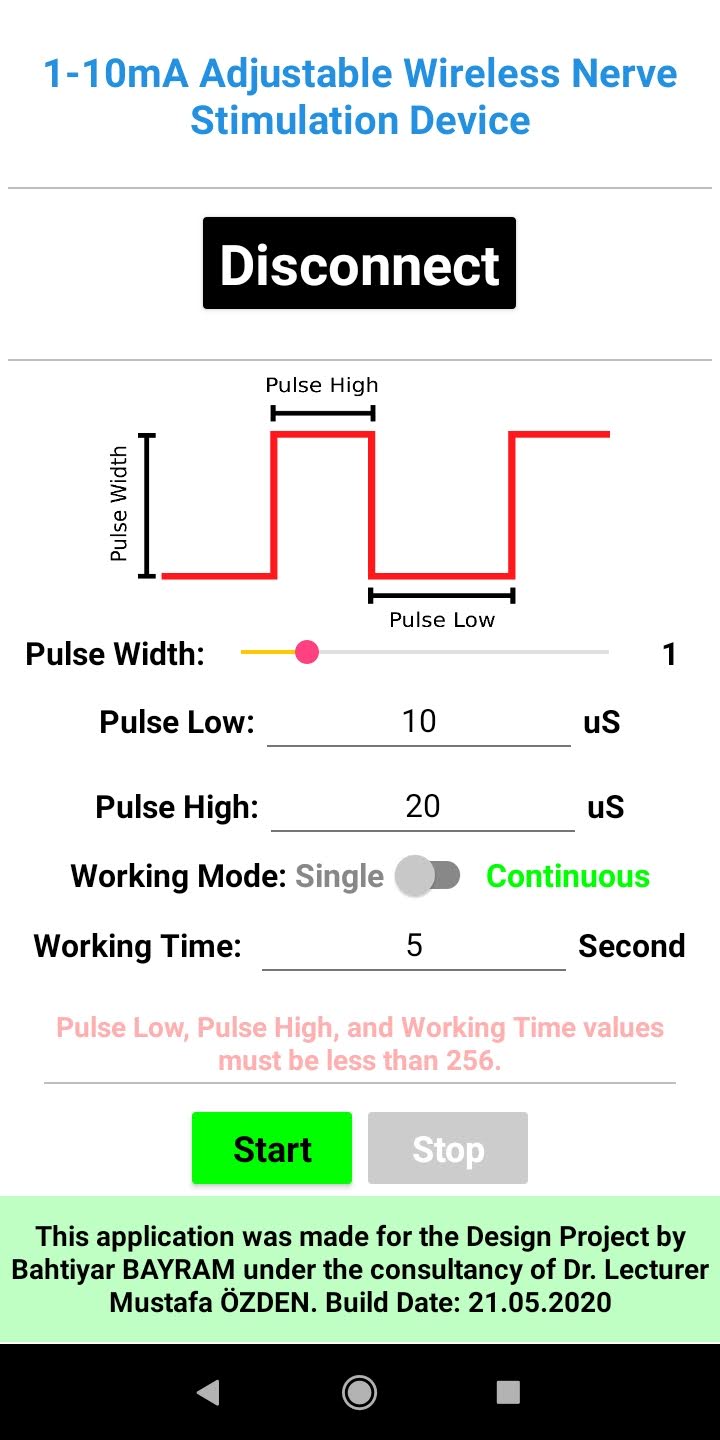 |
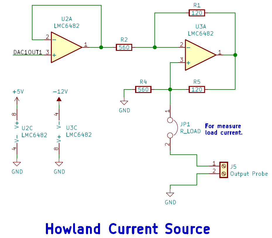 |  |
 |  |
 |  |
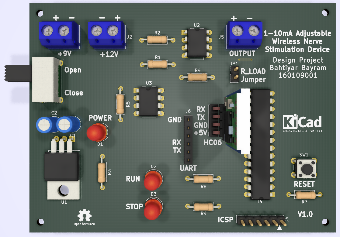
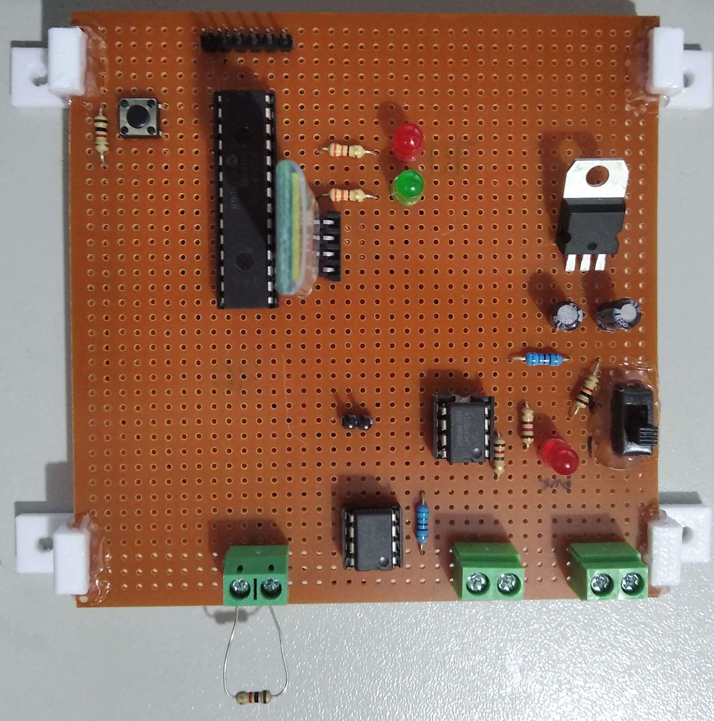
| Qty | Value | Footprint | References |
|---|---|---|---|
| 2 | 120 | Resistor_THT:R_Axial_DIN0207_L6.3mm_D2.5mm_P10.16mm_Horizontal | R1, R5 |
| 2 | 470 | Resistor_THT:R_Axial_DIN0207_L6.3mm_D2.5mm_P10.16mm_Horizontal | R8, R9 |
| 2 | 560 | Resistor_THT:R_Axial_DIN0207_L6.3mm_D2.5mm_P10.16mm_Horizontal | R2, R4 |
| 2 | LMC6482 | Package_DIP:DIP-8_W7.62mm_LongPads | U2, U3 |
| 1 | 0.1uF | Capacitor_THT:C_Radial_D5.0mm_H11.0mm_P2.00mm | C2 |
| 1 | 0.33uF | Capacitor_THT:C_Radial_D5.0mm_H11.0mm_P2.00mm | C1 |
| 1 | 100nF | Capacitor_THT:C_Disc_D4.7mm_W2.5mm_P5.00mm | C3 |
| 1 | 10k | Resistor_THT:R_Axial_DIN0207_L6.3mm_D2.5mm_P10.16mm_Horizontal | R7 |
| 1 | 12V PWR IN | TerminalBlock:TerminalBlock_bornier-2_P5.08mm | J2 |
| 1 | 1k | Resistor_THT:R_Axial_DIN0207_L6.3mm_D2.5mm_P10.16mm_Horizontal | R3 |
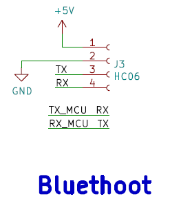
| 1 | HC06 | Connector_PinSocket_2.54mm:PinSocket_1x04_P2.54mm_Vertical | J3 |
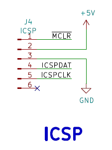
| 1 | ICSP | Connector_PinHeader_2.54mm:PinHeader_1x06_P2.54mm_Vertical | J4 |
| 1 | L7805 | Package_TO_SOT_THT:TO-220-3_Horizontal_TabDown | U1 |
| 1 | Output Probe | TerminalBlock:TerminalBlock_bornier-2_P5.08mm | J5 |
| 1 | PIC16F1713-ISP | Package_DIP:DIP-28_W7.62mm_LongPads | U4 |
| 1 | PWR | LED_THT:LED_D5.0mm | D1 |
| 1 | PWR IN | TerminalBlock:TerminalBlock_bornier-2_P5.08mm | J1 |
| 1 | Power SW | Button_Switch_THT:SW_E-Switch_EG1224_SPDT_Angled | SW2 |
| 1 | RESET | Button_Switch_THT:SW_PUSH_6mm_H5mm | SW1 |
| 1 | RUN | LED_THT:LED_D5.0mm | D2 |
| 1 | R_LOAD | Connector_PinHeader_2.54mm:PinHeader_1x02_P2.54mm_Vertical | JP1 |
| 1 | STOP | LED_THT:LED_D5.0mm | D3 |
| 1 | UART_Debug | Connector_PinSocket_2.54mm:PinSocket_1x06_P2.54mm_Vertical | J6 |
The 27 most common of 33 parts.

neurotech-berkeley/eog-eye-tracking
Exploration of EOG (electrooculogram) signals as a potential human computer interface


It measures 100 × 75 mm and has 2 copper layers, 1.6 mm thick.
33 parts, built around the LMC6482IN and L7805. The full list of its parts is on this page, with links to each part's symbol and footprint where PCBKit's library has them.
From the ElektroNeo/Adjustable-Wireless-Neuro-Stimulator-System repository on GitHub, at the commit this page was made from: the board is Hardware/adjustable-wireless-neuro-stimulator-system/adjustable-wireless-neuro-stimulator-system.kicad_pcb. PCBKit opens the board in the browser, with nothing to install.
Its repository publishes it under the GPL-3.0 licence: you may reuse it on that licence's terms (keep the author's notice, and for a copyleft licence share your changes alike).