4 layers65 × 30 mm

 DinosaurPotato534/Unflying-Fish
A flying fish that doesn't fly
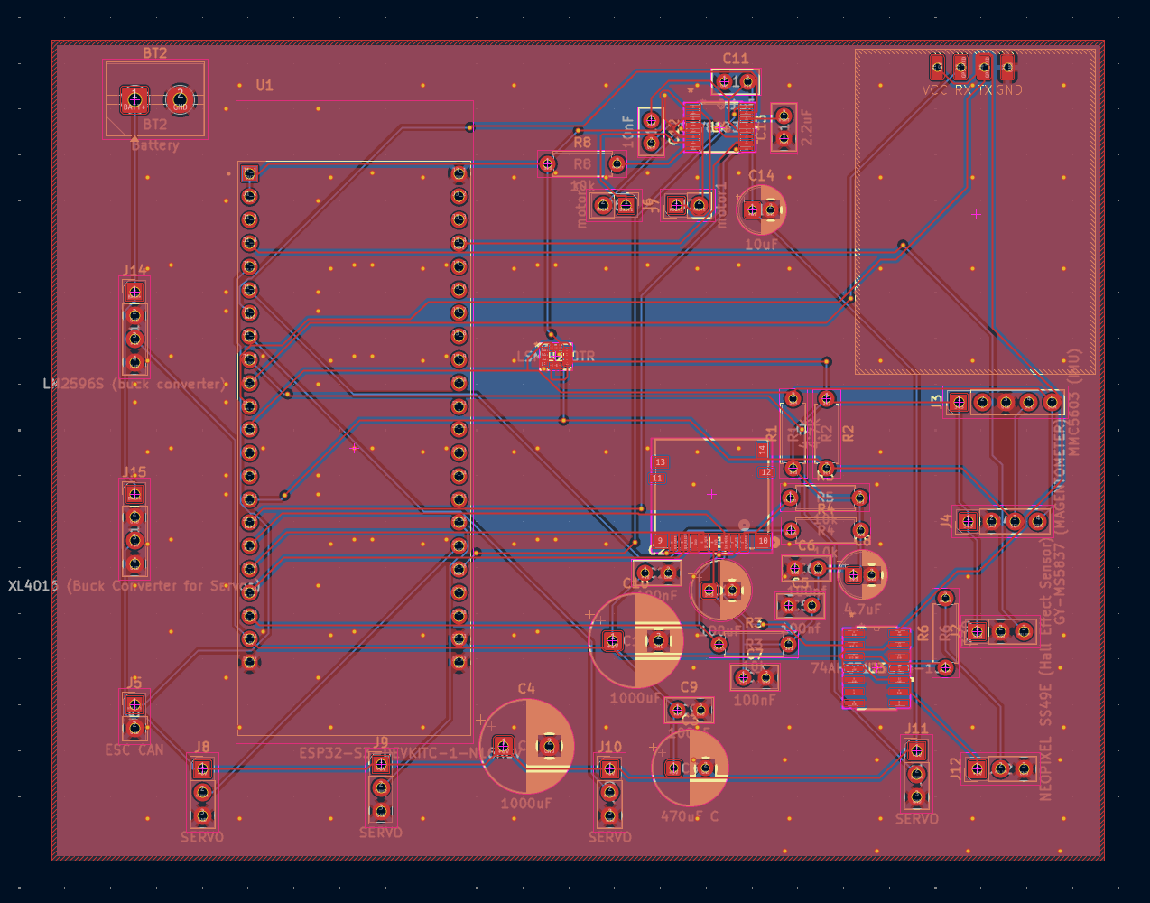
Unflying fish controller is an open-source printed circuit board by DinosaurPotato534, from the DinosaurPotato534/Unflying-Fish repository on GitHub. It is a 2-layer board of 114.9 × 89.5 mm with 41 parts on 61 nets, routed with 625 tracks and 174 vias.
It is built around the DRV8833PW and DM3D-SF. Its parts include 15 connectors, 14 capacitors, 7 resistors and 4 ICs. It belongs with the radio and wireless boards and the ESP32 boards of this library.


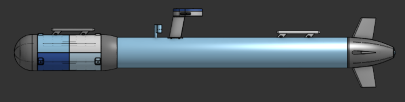
The main goal of the project was to create a full autonomous underwater vehicle capable of traveling below the surface with no signal. Water completely blocks out both GPS and WIFI, so we will have no connection at all once it submerges below the surface. Thus, the submarine can use gps to navigate above water to various waypoints and use dead-reckoning when navigating underwater.
Both of us (Shaan and Dimitri) have had an interest in amphibious vehicles capable of transferring between water, land, and air. This is one of our first steps in testing underwater systems and learning more about process.
For all the 3D printed parts be decided to go with a modular ribbed hull design as it was significantly more efficient in filament. It also greatly reduced support material and made many parts much more printable. The hull works by having a mostly thin outer shell (1.4mm) with several 4mm ribs running across. Then, rings would be nested in these ribs to further support both the walls and anything inside.
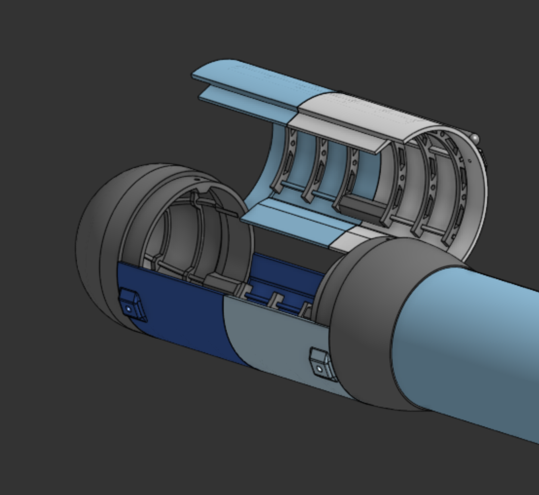
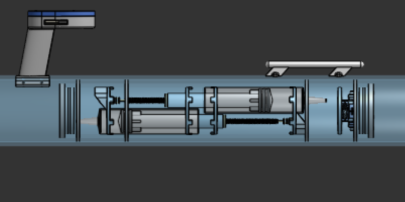
One of the more complicated aspects of the sub was the ballast system. Many other submarines use compressed air to fill a tank, but that requires a pump and only functions a few times before air runs out. Instead, we decided to use a dual approach with a lead screw driving two syringes for precise ballast control. Then, once at the surface and air-pump will fill up plastic bags to push the sub fully out of the water.
The antenna tower is relatively simple, housing both the GPS and ESP-32 Wifi antenna for signal. It also has a window to house LEDs to make the sub more visible when it is barely emerged from the surface.
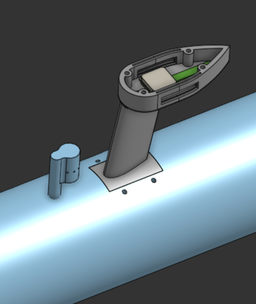
The main hull consists of a 4in pvc pipe, which everything else will be connected to. Antenna tower, for example, will be epoxied and bolted into the top surface of the pipe, with holes drilled through for wires.
The 3d printed nose will be assembled in multiple smaller parts first. Each quarter will be printed with vertically. Then, the flat ring ribs will be slid down the hull until it reaches its desired spot and epoxied into place. The tail will also be assembled in a similar way.
The electronics bay is a pvc pipe housing all the main electronics, such the battery and flight controller, and will removable from the nose. The nose compartment, which was seen earlier and can be opened, will be close using hose clamps
The end caps for both electronic bays will be 3d printed, but filled with epoxy to seal them. An o-ring will be added on a notch to complete the seal.
The ballast system will be assembled by putting the syringes into custom mounts in the pipe. Then the syringe head will be connected to the lead screw, which is driven by a small dc motor. The servos controlling the tail flaps will also be in this compartment. They will be sealed by rubber bellows and have push/pull rods leading to the back.
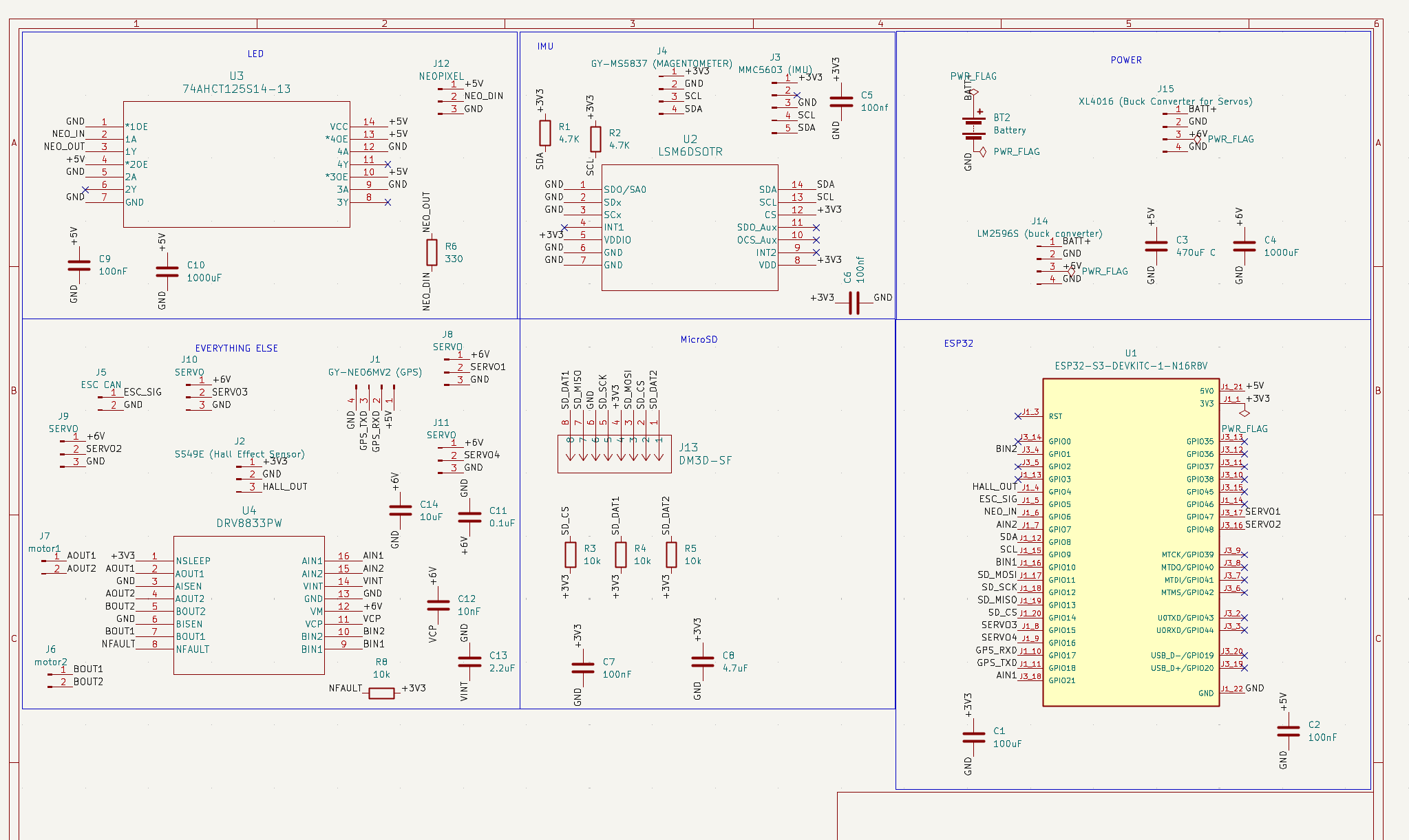
The project features a custom control board with all sensors soldered, with the exception of a few modules which we opted to be breakouts to limit corruption of signal. The board is optimized to limit noise, and includes a ground pour. The board was fully designed in KiCad within the size constraints laid out by CAD.
The craft is powered by an ESP32 S3 with a 4S LiPo battery.
The projects code will be written in PlatformIO and feature a web-based interface to launch missions, automatic surfacing, and fault-recovery. We will use dead-reckoning to localize the crafts position based on a number of sensors, including custom water flow rate, magnetometer, and gps re-centering on surface. We will account for current using the magnetometer, thrust, and flow rate sensor. The code architecture is fully defined, and the code will be written once the craft is built and verified to ensure efficiency and accuracy.
| Category | Cost (USD) |
|---|---|
| AliExpress Shipping | $9.58 |
| Underwater Thruster Shipping | $19.00 |
| DigiKey Shipping | $6.65 |
| Adafruit Shipping | $6.52 |
| Home Depot Shipping | $0.00 |
| Amazon Shipping | $0.00 |
| JLC Shipping | $8.59 |
| Total (pre-shipping) | $540.10 |
| Total (post-shipping) | $590.44 |
| Qty | Value | Footprint | References |
|---|---|---|---|
| 4 | 10k | Resistor_THT:R_Axial_DIN0207_L6.3mm_D2.5mm_P7.62mm_Horizontal | R3, R4, R5, R8 |
| 4 | SERVO | Connector_PinHeader_2.54mm:PinHeader_1x03_P2.54mm_Vertical | J8, J9, J10, J11 |
| 3 | 100nF | Capacitor_THT:C_Disc_D5.0mm_W2.5mm_P2.50mm | C2, C7, C9 |
| 2 | 1000uF | Capacitor_THT:CP_Radial_D10.0mm_P5.00mm | C4, C10 |
| 2 | 100nf | Capacitor_THT:C_Disc_D5.0mm_W2.5mm_P2.50mm | C5, C6 |
| 2 | 4.7K | Resistor_THT:R_Axial_DIN0207_L6.3mm_D2.5mm_P7.62mm_Horizontal | R1, R2 |
| 1 | 0.1uF | Capacitor_THT:C_Disc_D5.0mm_W2.5mm_P2.50mm | C11 |
| 1 | 100uF | Capacitor_THT:CP_Radial_D6.3mm_P2.50mm | C1 |
| 1 | 10nF | Capacitor_THT:C_Disc_D5.0mm_W2.5mm_P2.50mm | C12 |
| 1 | 10uF | Capacitor_THT:CP_Radial_D5.0mm_P2.00mm | C14 |
| 1 | 2.2uF | Capacitor_THT:C_Disc_D5.0mm_W2.5mm_P2.50mm | C13 |
| 1 | 330 | Resistor_THT:R_Axial_DIN0207_L6.3mm_D2.5mm_P7.62mm_Horizontal | R6 |
| 1 | 4.7uF | Capacitor_THT:CP_Radial_D5.0mm_P2.00mm | C8 |
| 1 | 470uF C | Capacitor_THT:CP_Radial_D8.0mm_P3.50mm | C3 |
| 1 | 74AHCT125S14-13 | Unflying Fish:74AHCT125S14-13 | U3 |
| 1 | Battery | TerminalBlock:TerminalBlock_MaiXu_MX126-5.0-02P_1x02_P5.00mm | BT2 |
| 1 | DM3D-SF | Unflying Fish:CONN8_DM3D-SF_HIR | J13 |
| 1 | DRV8833PW | afishthatdoesntfly:PW16_TEX | U4 |
| 1 | ESC CAN | Connector_PinHeader_2.54mm:PinHeader_1x02_P2.54mm_Vertical | J5 |
| 1 | ESP32-S3-DEVKITC-1-N16R8V | Unflying Fish:ESP32-S3-DEVKITC-1-N16R8V | U1 |
| 1 | GY-MS5837 (MAGENTOMETER) | Connector_PinHeader_2.54mm:PinHeader_1x04_P2.54mm_Vertical | J4 |
| 1 | GY-NEO6MV2 (GPS) | Unflying Fish:GY-GPS6MV2 | J1 |
| 1 | LM2596S (buck converter) | Connector_PinHeader_2.54mm:PinHeader_1x04_P2.54mm_Vertical | J14 |
| 1 | LSM6DSOTR | Unflying Fish:LSM6DSOTR | U2 |
| 1 | MMC5603 (IMU) | Connector_PinHeader_2.54mm:PinHeader_1x05_P2.54mm_Vertical | J3 |
| 1 | NEOPIXEL | Connector_PinHeader_2.54mm:PinHeader_1x03_P2.54mm_Vertical | J12 |
| 1 | SS49E (Hall Effect Sensor) | Connector_PinHeader_2.54mm:PinHeader_1x03_P2.54mm_Vertical | J2 |
| 1 | XL4016 (Buck Converter for Servos) | Connector_PinHeader_2.54mm:PinHeader_1x04_P2.54mm_Vertical | J15 |
| 1 | motor1 | Connector_PinHeader_2.54mm:PinHeader_1x02_P2.54mm_Vertical | J7 |
| 1 | motor2 | Connector_PinHeader_2.54mm:PinHeader_1x02_P2.54mm_Vertical | J6 |

hasenbanck/heteromycin
A 3D printer board using a powerfull STM32 MCU, TMC5160/TMC2160 driver and a Raspberry Pi or compatible SBC

atomic14/esp32-tv-hardware
This is Work In Progress - I'm still working on this.


will-tm/gbc-cm4-aio
This project is a drop-in replacement board that fits and Gameboy Color shell and use the same IPS display as used in GBC kits.


patkan/lightning-detector
Lightning Detector ethernet sensor node and server based on AS3935 - this project is discontinued
It measures 114.9 × 89.5 mm and has 2 copper layers, 1.6 mm thick.
41 parts, built around the DRV8833PW and DM3D-SF. The full list of its parts is on this page, with links to each part's symbol and footprint where PCBKit's library has them.
From the DinosaurPotato534/Unflying-Fish repository on GitHub, at the commit this page was made from: the board is pcb/unflying-fish-controller/unflying-fish-controller.kicad_pcb and its schematic pcb/unflying-fish-controller/unflying-fish-controller.kicad_sch. PCBKit opens the board in the browser, with nothing to install.
Its repository states no licence, so its author keeps all rights: ask DinosaurPotato534 before reusing the design.