2 layers33.2 × 40 mm

 Dheemanth0207/Electronic-Conference-Badge
This project investigates the design and development of a smart, energy-efficient electronic conference badge intended to replace traditional printed name tags used at events and meetings.
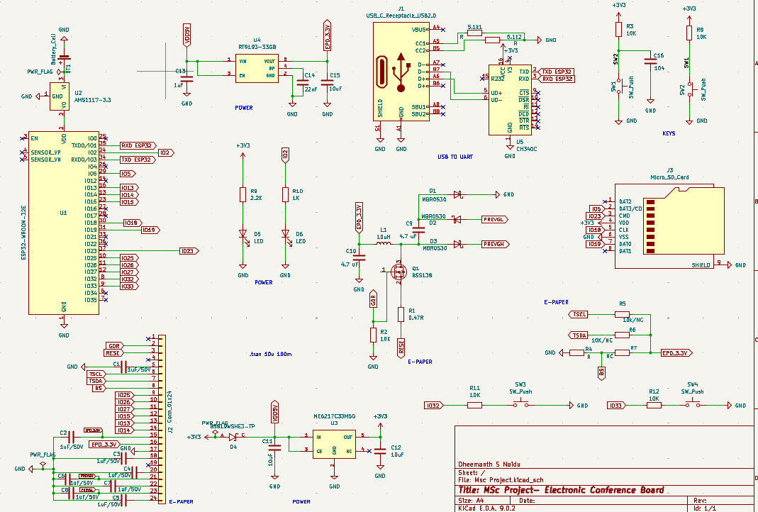
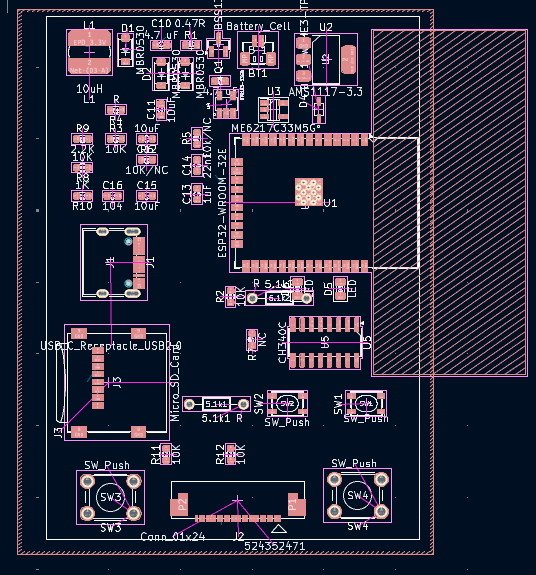
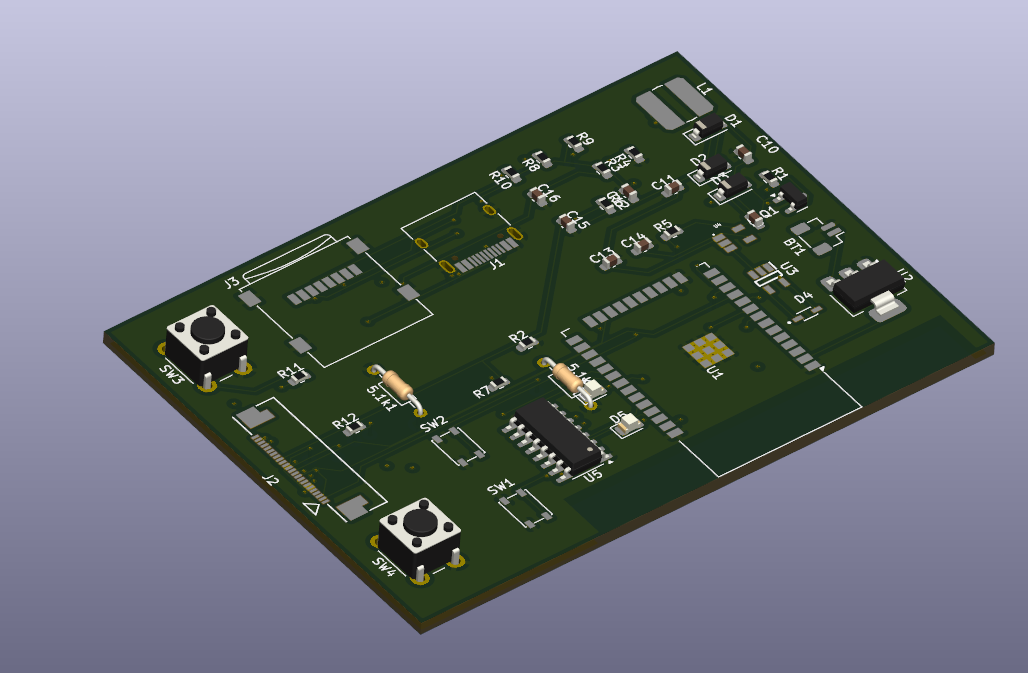
Conference Badge is an open-source printed circuit board by Dheemanth0207, from the Dheemanth0207/Electronic-Conference-Badge repository on GitHub. It is a 4-layer board of 52 × 73 mm with 51 parts on 90 nets, routed with 465 tracks and 63 vias.
It is built around the CH340C, ESP32-WROOM-32E and AMS1117-3.3, with the ME6217C33M5G, RT9193-33GB and MBR0530 among its other parts. Its parts include 16 capacitors, 12 resistors, 6 diodes, 3 ICs and 1 transistor. It belongs with the lEDs and displays boards and the ESP32 boards of this library.


This project investigates the design and development of a smart, energy-efficient electronic conference badge intended to replace traditional printed name tags used at events and meetings. The system is built around a compact microcontroller board, which controls a 3.52-inch e-paper display capable of showing attendee names, designations, or other event-specific content. Unlike conventional displays, e-paper offers excellent readability in various lighting conditions, including bright sunlight, while consuming very little power, making it ideal for multi-day usage on a single charge.
The badge is designed to be interactive and easily programmable, featuring a set of physical buttons for input and wireless communication that allow it to connect with other badges or systems for capabilities such as contact exchange, activity tracking, or peer-to-peer messaging. A SD card reader also provides the flexibility to update the badge content without relying on an internet connection, making it useful in both connected and standalone scenarios
To reliably support all of these features, the hardware integrates a combination of power management circuits to ensure stable operation across different use cases. These include a voltage regulator and boost converter to provide the necessary voltages for the logic components and display. The board is powered by a 3.7V rechargeable battery and is charged or programmed via a USB Type-C connector.
All design work, including schematic creation and PCB layout, was completed using the open-source KiCAD 9 design tool, ensuring that the board is optimized for surface-mount manufacturing. By combining low-power electronics, open-source design tools, and a thoughtful user interface, this badge system offers a modern, reusable, and sustainable alternative to traditional paper-based identification at events.
To view, edit, or manufacture this project, the following software is required:
Download and install the latest version of KiCad from the official website:
https://www.kicad.org/download/
Verify that KiCad is correctly installed by launching the application and opening the Project Manager.
git clone https://github.com/<your-username>/<repository-name>.git
cd <repository-name>
Alternatively, download the project as a ZIP file and extract it to your desired location.
.kicad_pro file.The project schematic, PCB layout, symbols, footprints, and manufacturing files will now be available through the KiCad Project Manager.
Project/
│
├── Hardware/
│   ├── Schematics/
│   ├── PCB/
│   ├── Libraries/
│   └── Manufacturing/
│
├── Documentation/
│   ├── Images/
│   └── Datasheets/
│
└── README.mdTo generate fabrication files:
Contributions, suggestions, and improvements are welcome. Please fork the repository, create a feature branch, and submit a pull request describing your changes.
| Qty | Value | Footprint | References |
|---|---|---|---|
| 8 | 1uF/50V | Capacitor_SMD:C_0603_1608Metric | C1, C2, C3, C4, C5, C6, C7, C8 |
| 5 | 10K | Resistor_SMD:R_0603_1608Metric | R2, R3, R8, R11, R12 |
| 3 | 10uF | Capacitor_SMD:C_0603_1608Metric | C11, C12, C15 |
| 3 | MBR0530 | Diode_SMD:D_SOD-123 | D1, D2, D3 |
| 2 | 4.7 uF | Capacitor_SMD:C_0603_1608Metric | C9, C10 |
| 2 | LED | LED_SMD:LED_0805_2012Metric | D5, D6 |
| 2 | R | Resistor_THT:R_Axial_DIN0204_L3.6mm_D1.6mm_P7.62mm_Horizontal | 5.1k1, 5.1k2 |
| 2 | SW_Push | Button_Switch_THT:SW_PUSH_6mm | SWITCH1, SWITCH2 |
| 1 | 0.47R | Resistor_SMD:R_0603_1608Metric | R1 |
| 1 | 104 | Capacitor_SMD:C_0603_1608Metric | C16 |
| 1 | 10K/NC | Resistor_SMD:R_0603_1608Metric | R6 |
| 1 | 10k/NC | Resistor_SMD:R_0603_1608Metric | R5 |
| 1 | 10uH | Inductor_SMD:L_Bourns_SDR0604 | L1 |
| 1 | 1K | Resistor_SMD:R_0603_1608Metric | R10 |
| 1 | 1uF | Capacitor_SMD:C_0603_1608Metric | C13 |
| 1 | 2.2K | Resistor_SMD:R_0603_1608Metric | R9 |
| 1 | 22nF | Capacitor_SMD:C_0603_1608Metric | C14 |
| 1 | AMS1117-3.3 | Package_TO_SOT_SMD:SOT-223-3_TabPin2 | U2 |
| 1 | B5819WSHE3-TP | B5819WSHE3-TP:SOD2512X115N | D4 |
| 1 | BOOT | Button_Switch_SMD:SW_SPST_PTS810 | BOOT |
| 1 | BSS138 | Package_TO_SOT_SMD:SOT-23 | Q1 |
| 1 | Battery_Cell | Connector_JST:JST_SH_BM02B-SRSS-TB_1x02-1MP_P1.00mm_Vertical | JST 2 PIN |
| 1 | CH340C | Package_SO:SOIC-16_3.9x9.9mm_P1.27mm | CH340 |
| 1 | Conn_01x24 | 524352471:CON_524352471_MOL | 18 CONNECTOR |
| 1 | EN | Button_Switch_SMD:SW_SPST_PTS810 | EN |
| 1 | ESP32-WROOM-32E | RF_Module:ESP32-WROOM-32D | ESP32 |
| 1 | ME6217C33M5G | ME6217C33M5G:SOT23-5 | U3 |
| 1 | Micro_SD_Card | Connector_Card:microSD_HC_Wuerth_693072010801 | SD CARD |
| 1 | NC | Resistor_SMD:R_0603_1608Metric | R7 |
| 1 | R | Resistor_SMD:R_0603_1608Metric | R4 |
| 1 | RT9193-33GB | RT9193-33GB:SOT94P279X129-5N | U4 |
| 1 | USB_C_Receptacle_USB2.0 | Connector_USB:USB_C_Receptacle_HRO_TYPE-C-31-M-12 | USB C |

fulvionardi/Epaper
This project is a replication of the Waveshare 3.6inch e-Paper HAT+ schematics, originally documented in 3.6inche-PaperHAT+Schematics.pdf.

ANSHUMANDOCX/ESP32-LCD-Study-Tracker
Its a Study tracker that helps you be productive while studying along with maintaining a day wise log online on the website hosted on the ESP32 itself

camelone49/HishBoard_v1
This is a repo for my new gaming keyboard, which will include all files (eventually =) )

ANSHUMANDOCX/ESP32-Touch-Hub
This is a Esp32 Hub that has a 3.5 inch tft touch screen


SRA-VJTI/sra-board-hardware-design
ESP32-based Development Board for Robotics and Embedded Applications

ricardoquesada/unijoysticle2
Bluetooth gamepad support for the Commodore 64 / Atari / Amiga, etc.
It measures 52 × 73 mm and has 4 copper layers, 1.6 mm thick.
51 parts, built around the CH340C, ESP32-WROOM-32E, AMS1117-3.3 and ME6217C33M5G. The full list of its parts is on this page, with links to each part's symbol and footprint where PCBKit's library has them.
From the Dheemanth0207/Electronic-Conference-Badge repository on GitHub, at the commit this page was made from: the board is Conference Badge.kicad_pcb and its schematic Conference Badge.kicad_sch. PCBKit opens the board in the browser, with nothing to install.
Its repository states no licence, so its author keeps all rights: ask Dheemanth0207 before reusing the design.