2 layers50.8 × 33 mm

 DavidVeloz95/Open-Source-Battery-Smart-Charger
Embedded power electronics project: intelligent 2S Li-Ion charger with protection, power switching and monitoring, designed in KiCad.
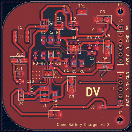
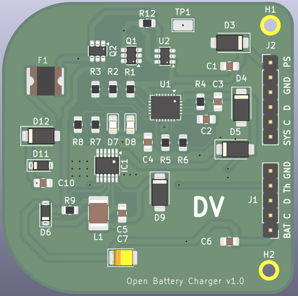
Open Battery Charger is an open-source printed circuit board by DavidVeloz95, from the DavidVeloz95/Open-Source-Battery-Smart-Charger repository on GitHub, published under the MIT licence. It is a 2-layer board of 50 × 50 mm with 47 parts on 42 nets, routed with 262 tracks and 28 vias.
It is built around the LT3650EMSE-8.4#PBF, TPS26600RHFR and CMSH3-40MA, with the FDC610PZ, BAV70 and KDZVTR12B among its other parts. Its parts include 12 resistors, 12 diodes, 10 capacitors, 3 ICs and 2 transistors. It belongs with the power boards of this library.


Smart 2S Li-Ion battery charger designed in KiCad featuring input protection, power-path management, and intelligent charging control.
This project implements an intelligent battery charging system for 2-cell Li-Ion batteries (8.4V) with integrated protection and automatic power switching.
The system combines:
The design was developed in KiCad 10 as part of a hardware/electronics engineering portfolio project.
The input stage is protected using the TPS26600 eFuse, providing:
This stage protects downstream electronics from abnormal supply conditions.
Battery charging is managed using the LT3650, configured for:
The LTC4412 controller enables automatic switching between:
This ensures uninterrupted system operation while preventing reverse current paths.
A dedicated 3.3V LDO regulator powers low-voltage logic and embedded systems.
| Component | Function |
|---|---|
| LT3650 | Smart battery charger |
| TPS26600 | Input protection / eFuse |
| LTC4412 | Ideal diode power-path controller |
| LDK320AM33R | 3.3V voltage regulator |
| Parameter | Value |
|---|---|
| Battery Type | 2S Li-Ion |
| Charge Voltage | 8.4V |
| Charging Method | CC/CV |
| Logic Rail | 3.3V |
| Input Protection | OVP / current limiting |
| Design Tool | KiCad 10 |
Open_Battery_Charger/
│
├── hardware/
│   ├── Open_Battery_Charger.kicad_pro
│   ├── Open_Battery_Charger.kicad_sch
│   ├── Open_Battery_Charger.kicad_pcb
│   └── fp-lib-table
│
├── docs/
│   ├── schematic.pdf
│   ├── schematic.png
│   ├── 2D_pcb_top.png
│   ├── 2D_pcb_bottom.png
│   ├── 3D_pcb_top.png
│   ├── 3D_pcb_bottom.png
│   ├── Detailed_Design_Procedure_LT3650.pdf
│   ├── Detailed_Design_Procedure_TPS2660
│   └── Open_Source_Battery_Smart_Charger_Specifications.pdf
│
└── production/
    ├── gerbers/
    └── bom.csv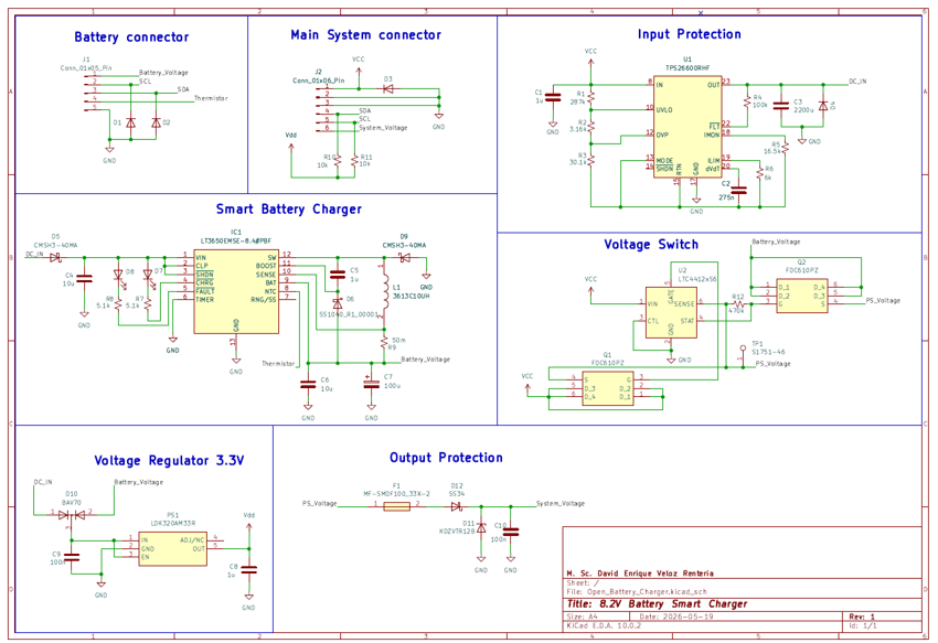
Key engineering decisions considered during development:
This project is released under the MIT License.
| Qty | Value | Footprint | References |
|---|---|---|---|
| 4 | SMAJ12A-HP6AT/13 | Diode_SMD:D_SMA | D1, D2, D3, D4 |
| 3 | 1u | Capacitor_SMD:C_0805_2012Metric_Pad1.18x1.45mm_HandSolder | C1, C5, C8 |
| 2 | 100n | Capacitor_SMD:C_0805_2012Metric_Pad1.18x1.45mm_HandSolder | C9, C10 |
| 2 | 10k | Resistor_SMD:R_0805_2012Metric | R10, R11 |
| 2 | 10u | Capacitor_SMD:C_0805_2012Metric_Pad1.18x1.45mm_HandSolder | C4, C6 |
| 2 | 5.1k | Resistor_SMD:R_0805_2012Metric | R7, R8 |
| 2 | CMSH3-40MA | Diode_SMD:D_SMA | D5, D9 |
| 2 | FDC610PZ | Package_TO_SOT_SMD:SuperSOT-6 | Q1, Q2 |
| 2 | MountingHole_2.2mm_M2_ISO7380_Pad | MountingHole:MountingHole_2.2mm_M2_ISO7380_Pad | H1, H2 |
| 1 | 100k | Resistor_SMD:R_0805_2012Metric | R4 |
| 1 | 100u | Capacitor_Tantalum_SMD:CP_EIA-3528-21_Kemet-B_HandSolder | C7 |
| 1 | 16.5k | Resistor_SMD:R_0805_2012Metric | R5 |
| 1 | 2200u | Capacitor_SMD:C_0805_2012Metric_Pad1.18x1.45mm_HandSolder | C3 |
| 1 | 275n | Capacitor_SMD:C_0805_2012Metric_Pad1.18x1.45mm_HandSolder | C2 |
| 1 | 287k | Resistor_SMD:R_0805_2012Metric | R1 |
| 1 | 3.16k | Resistor_SMD:R_0805_2012Metric | R2 |
| 1 | 30.1k | Resistor_SMD:R_0805_2012Metric | R3 |
| 1 | 3613C10UH | Capacitor_SMD:C_1812_4532Metric_Pad1.57x3.40mm_HandSolder | L1 |
| 1 | 470k | Resistor_SMD:R_0805_2012Metric | R12 |
| 1 | 50m | Resistor_SMD:R_0805_2012Metric | R9 |
| 1 | 6k | Resistor_SMD:R_0805_2012Metric | R6 |
| 1 | BAV70 | Package_TO_SOT_SMD:SOT-23 | D10 |
| 1 | Conn_01x05_Pin | Connector_PinHeader_2.54mm:PinHeader_1x05_P2.54mm_Vertical | J1 |
| 1 | Conn_01x06_Pin | Connector_PinHeader_2.54mm:PinHeader_1x06_P2.54mm_Vertical | J2 |
| 1 | KDZVTR12B | Diode_SMD:D_SOD-123 | D11 |
| 1 | LDK320AM33R | Package_TO_SOT_SMD:SOT-23-5_HandSoldering | PS1 |
| 1 | LT3650EMSE-8.4#PBF | Package_SO:MSOP-12-1EP_3x4.039mm_P0.65mm_EP1.651x2.845mm_ThermalVias | IC1 |
| 1 | LTC4412xS6 | Package_TO_SOT_SMD:TSOT-23-6 | U2 |
| 1 | MF-SMDF100_33X-2 | David_Library:MF-SMDF100_33X-2 | F1 |
| 1 | Q62702P5178 | LED_SMD:LED_0805_2012Metric_Pad1.15x1.40mm_HandSolder | D8 |
| 1 | Q62702P5179 | LED_SMD:LED_0805_2012Metric_Pad1.15x1.40mm_HandSolder | D7 |
| 1 | S1751-46 | TestPoint:TestPoint_Keystone_5015_Micro_Mini | TP1 |
| 1 | SS1040_R1_00001 | Diode_SMD:D_SOD-123 | D6 |
| 1 | SS34 | Diode_SMD:D_SMA | D12 |
| 1 | TPS26600RHF | Package_DFN_QFN:Texas_RHF0024A_VQFN-24-1EP_4x5mm_P0.5mm_EP2.65x3.65mm_ThermalVias | U1 |


manhoosbilli1/atmega328-enclosure-tamper-alarm
ATmega328 AC enclosure tamper/intrusion alarm with LTC2960 voltage monitor, LTC4412 PowerPath, boost+buck converters

ben5049/switch-v4-hardware
KiCad design files for the 4th iteration of my single pair Ethernet (SPE) switch. The firmware can be found in unified-switch-firmware.

ben5049/switch-v5-hardware
KiCad design files for the 5th iteration of my single pair Ethernet (SPE) switch. It is similar to v4 but with more ports and an RJ45 connector so an external media converter isn't needed to connect to regular Ethernet…

ben5049/cm-carrier-hardware
Compact CM5 carrier board with an M.2 E-key connector and a 1000BASE-T1 Ethernet PHY, as well as other optional IO.

AnasSarkiz/smart-nema14-motor-controller
STEPPERONLINE 14HM11-0404S controller — unrouted work-in-progress prototype; mechanical and electrical qualification pending
It measures 50 × 50 mm and has 2 copper layers, 1.6 mm thick.
47 parts, built around the LT3650EMSE-8.4#PBF, TPS26600RHFR, CMSH3-40MA and FDC610PZ. The full list of its parts is on this page, with links to each part's symbol and footprint where PCBKit's library has them.
From the DavidVeloz95/Open-Source-Battery-Smart-Charger repository on GitHub, at the commit this page was made from: the board is hardware/Open_Battery_Charger.kicad_pcb and its schematic hardware/Open_Battery_Charger.kicad_sch. PCBKit opens the board in the browser, with nothing to install.
Its repository publishes it under the MIT licence: you may reuse it on that licence's terms (keep the author's notice, and for a copyleft licence share your changes alike).