
4 layers80 × 85 mm
Mainboard v13
DVA490-474-Project-Course/SSL-Hardware-Development
Contains all hardware related material. (No software).
118 partsMIT

 DVA490-474-Project-Course/SSL-Hardware-Development
Contains all hardware related material. (No software).
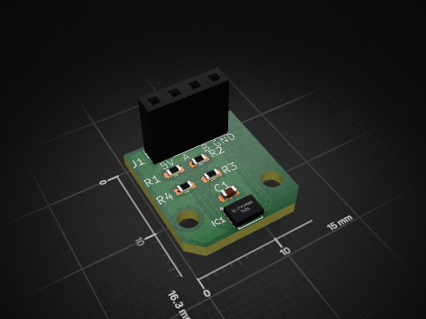
Kicker Control Circuit is an open-source printed circuit board by DVA490-474-Project-Course, from the DVA490-474-Project-Course/SSL-Hardware-Development repository on GitHub, published under the MIT licence. It is a 2-layer board of 38.5 × 33 mm with 14 parts on 10 nets, routed with 39 tracks and 7 vias.
It is built around the IKB40N65ES5ATMA1, UCC27511DBVR(UMW) and VS-5EWH06FN-M3. Its parts include 4 resistors, 3 capacitors, 3 connectors, 2 ICs and 1 diode.
Welcome to the SSL Robot Project repository! This project encompasses both hardware and software components essential for building and controlling an SSL robot. Our goal is to create a robust, scalable, and maintainable robot platform.
/SSL-Robot-Project
├── /3D_Models
│   ├── /CAD_Files            # All CAD files for different robot parts
│   ├── /STL_Files            # STL exports for 3D printing
│   └── /Renderings           # Renders of the 3D models
├── /Circuits
│   ├── /Motor_Control        # Motor circuit design files
│   ├── /Kicker               # Kicker circuit design files
│   ├── /Dribbler             # Dribbler circuit design files
│   └── /Sensor               # Sensor circuit design files
├── /BOM                      # Bill of Materials for different components
├── /Software
│   ├── /Motor_Control
│   │   ├── /Firmware          # Firmware code for motor controllers
│   │   │   ├── /src           # Source code files
│   │   │   ├── /include       # Header files
│   │   │   ├── /tests         # Unit and integration tests
│   │   │   └── README.md      # Firmware-specific documentation
│   │   ├── /Software_Doc      # Documentation related to motor control software
│   │   │   ├── /API_Docs      # API documentation if applicable
│   │   │   └── /User_Guides   # User manuals or setup guides
│   │   ├── /Libraries         # Any libraries or dependencies specific to motor control
│   │   └── /Examples          # Example projects or usage scenarios
│ ├── /Kicker_Control # Similar structure for kicker control softwareClone the Repository
git clone git@github.com:DVA490-474-Project-Course/SSL-Hardware-Development.git
cd SSL-Robot-Project
Setup Software Environment
cd Software/Motor_ControlREADME.md to build and deploy the firmware.Accessing Documentation
We welcome contributions! Please read our CONTRIBUTING.md for guidelines on how to get involved.
This project is licensed under the MIT License.
For any questions or support, please open an issue or contact the project maintainers.
Pontus Svensson - psn19003@student.mdu.se
| Qty | Value | Footprint | References |
|---|---|---|---|
| 3 | 10k | Resistor_SMD:R_1210_3225Metric | R1, R2, R3 |
| 2 | 0.1u | Capacitor_SMD:C_0805_2012Metric_Pad1.18x1.45mm_HandSolder | C1, C2 |
| 2 | Conn_01x02_Pin | Connector_PinHeader_2.54mm:PinHeader_1x02_P2.54mm_Vertical | J1, J2 |
| 1 | 100 | Resistor_SMD:R_2010_5025Metric | R4 |
| 1 | 1u | Capacitor_SMD:C_0805_2012Metric_Pad1.18x1.45mm_HandSolder | C3 |
| 1 | Conn_01x03_Pin | Connector_PinHeader_2.54mm:PinHeader_1x03_P2.54mm_Vertical | J3 |
| 1 | Diode | Diode_SMD:D_SMC | D1 |
| 1 | IKB40N65ES5ATMA1 | IKB40N65ES5ATMA1 IGBT:BTS141TCBUMA1 | Q2 |
| 1 | UCC27511DBVR | UCC27511DBVR:SOT95P280X145-6N | IC1 |
| 1 | VS-5EWH06FN-M3 | VS-5EWH06FN-M3:DPAK_06FN-M3_VIS | U2 |
DVA490-474-Project-Course/SSL-Hardware-Development
Contains all hardware related material. (No software).

DVA490-474-Project-Course/SSL-Hardware-Development
Contains all hardware related material. (No software).

DVA490-474-Project-Course/SSL-Hardware-Development
Contains all hardware related material. (No software).

DVA490-474-Project-Course/SSL-Hardware-Development
Contains all hardware related material. (No software).

DVA490-474-Project-Course/SSL-Hardware-Development
Contains all hardware related material. (No software).

DVA490-474-Project-Course/SSL-Hardware-Development
Contains all hardware related material. (No software).
DVA490-474-Project-Course/SSL-Hardware-Development
Contains all hardware related material. (No software).

quasiengineer/i8080-sbc
FPGA-based single board computer to run Intel 8080 CPU (up to 3.125Mhz)

jakeson21/LM3409HV-30W-LED
30W LED driver based on a TI LM3409HV buck controller

ldcyes/OpenDuck
已完成可编辑原理图、真实四层 PCB 和本地库。阶梯板面积 4510 mm²,比原 65×60 + 32×30 mm 两板总面积 4860 mm² 少 350 mm²(7.20%)。原 TDK 模块本体、四个安装孔和原 TDK 器件位置保留,回生电容采用原料号卧装,J1 因实际拔插通道冲突改为同系列 BM08 顶插。当前为工程候选,未制造,未完成热、回生瞬态、低电量或行走验收。

Wassasin/leddimmer
Quick low-side PWM device to crudely dim two 24V 4A LED strips

google/mozc-devices
Circuit diagrams and firmware source code for Gboard DIY keyboards


hackclub/OnBoard
💡 Join 1,000 teenagers and make your first PCB with a $100 grant!

It measures 38.5 × 33 mm and has 2 copper layers, 1.6 mm thick.
14 parts, built around the IKB40N65ES5ATMA1, UCC27511DBVR(UMW) and VS-5EWH06FN-M3. The full list of its parts is on this page, with links to each part's symbol and footprint where PCBKit's library has them.
From the DVA490-474-Project-Course/SSL-Hardware-Development repository on GitHub, at the commit this page was made from: the board is Circuits/Kicker_Control/Kicker_Control_Circuit/Kicker_Control_Circuit.kicad_pcb. PCBKit opens the board in the browser, with nothing to install.
Its repository publishes it under the MIT licence: you may reuse it on that licence's terms (keep the author's notice, and for a copyleft licence share your changes alike).