2 layers21.9 × 17.1 mm
AlimTeleinfoMySensors
tdouez/TeleinfoMySensors
Interface Téléinfo pour compteur Linky avec MySensors
14 parts14

 Cosys-Lab/lab-scale-gantry-crane4
Repository containing the files to create the lab-scale gantry crane used in a couple of publications.
Gantry shield is an open-source printed circuit board by Cosys-Lab, from the Cosys-Lab/lab-scale-gantry-crane repository on GitHub, published under the MIT licence. It is a 2-layer board of 68.6 × 53.3 mm with 26 parts on 55 nets, routed with 148 tracks and 7 vias.
It is built around the TL084 and BS170FTA. Its parts include 11 resistors, 8 connectors, 1 IC, 1 diode and 1 transistor.


This repository describes a lab-scale gantry crane digital twin exemplar. This exemplar was used in a couple of our publications. This readme only contains basic information, for the complete documentation, head to github pages.
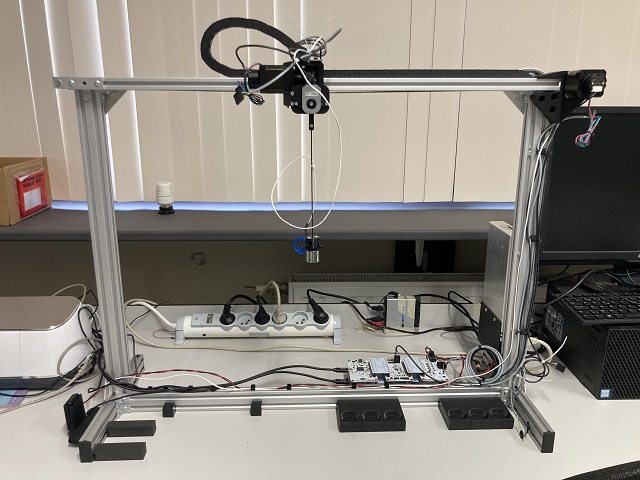
The repository is structured as follows:
Refer to the build guide on GitHub Pages.
Install Python. On Windows, preferably use Python 3.13 or higher, since earlier versions have a low resolution (only 15.6 ms) of the time() and datetime.now() functions, which are used often in the code.
Install the gantrylib module locally as editable installation. From the root of the repository folder, run:
python -m pip install -e .The software relies on a TimescaleDB database, a Grafana dashboard and, optinally an MQTT broker. The setup files of all of these are contained in the docker folder. Assuming docker and docker compose are installed, from the docker folder, it suffices to run:
docker compose upThe containers can then be started and stopped with:
docker compose stop
docker compose start
To remove the containers and the network connecting them, run:
docker compose downThe config is exceptionally insecure, since all of the default usernames/passwords are used. If this is a problem, do change them.
The MQTT broker is really only needed if you want to run the TrajectoryGenerator service in its MQTT mode. Ofter services (Simulator, Validator) have in this release not yet been implemented in MQTT mode.
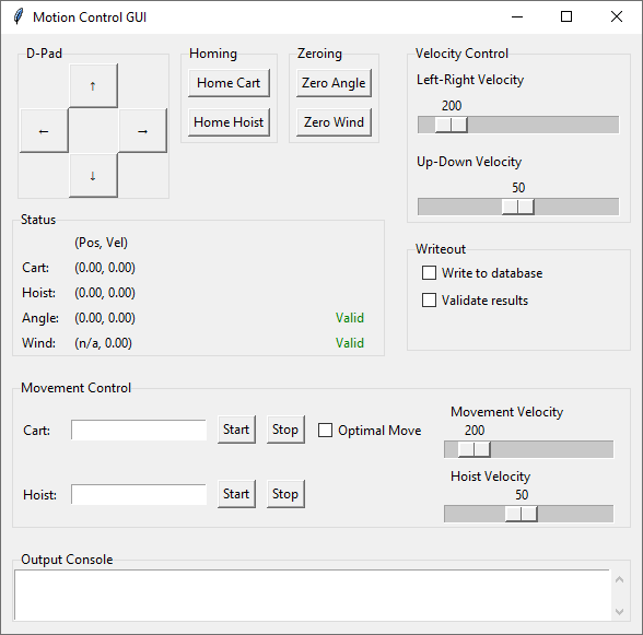
Assuming you went through the software setup and built the crane according to the hardware quickstart, the fastest way to get the crane to do something is using the run_with_hmi.py example. A short video demonstrating the example can be found on youtube.
You will have to configure crane-properties.yaml for your specific installation, more specifically, specify the serial ports of the two motor controller boards. Unfortunately, the Trinamic devkits don't offer a unique ID that allows you to identify them, therefore we recommend plugging in the boards one by one, and noting down the serial ports that appear as you plug them in (in device manager/Ports (COM & LPT) in Windows, or under /dev/tty* in Linux.)
Once you have noted down those ports, update the following two fields in the config:
cart_motor_port: COM13
...
hoist_motor_port: COM8
You can now run the example.
Upon first starting, it will home the cart and hoist motor. Homing the cart motor happens automatically, homing the hoist motor must be done with some manual user input. The script prompts you to confirm this on the command line. Afterwards you will see the simple HMI interface that allows you to move the crane.
Below are publications in which this exemplar was used:
J. Mertens and J. Denil, Localizing Faults in Digital Twin Models by Using Time Series Classification Techniques, 2024 Winter Simulation Conference (WSC), IEEE, Dec. 2024, pp. 2868–2879. https://doi.org/10.1109/wsc63780.2024.10838825
J. Mertens, S. Klikovits, F. Bordeleau, J. Denil, and Ø. Haugen, Continuous Evolution of Digital Twins using the DarTwin Notation, Software and Systems Modeling, p. 22, Nov. 2024. https://doi.org/10.1007/s10270-024-01216-7
J. Mertens and J. Denil, Reusing model validation methods for the continuous validation of digital twins of cyber-physical systems, Software and Systems Modeling, p. 23, Oct. 2024. https://doi.org/10.1007/s10270-024-01225-6
J. Mertens and J. Denil, Digital-twin Co-evolution using Continuous Validation, In Proceedings of the ACM/IEEE 14th International Conference on Cyber-Physical Systems (with CPS-IoT Week 2023), ICCPS ’23, San Antonio, TX, USA: ACM, 2023, pp. 266–267. https://doi.org/10.1145/3576841.3589628
| Qty | Value | Footprint | References |
|---|---|---|---|
| 5 | 100k | Resistor_THT:R_Axial_DIN0207_L6.3mm_D2.5mm_P10.16mm_Horizontal | R2, R4, R6, R8, R10 |
| 4 | 22k | Resistor_THT:R_Axial_DIN0207_L6.3mm_D2.5mm_P10.16mm_Horizontal | R5, R7, R9, R11 |
| 4 | MountingHole_3.2mm | Arduino_MountingHole:MountingHole_3.2mm | MH1, MH2, MH3, MH4 |
| 1 | 10k | Resistor_THT:R_Axial_DIN0207_L6.3mm_D2.5mm_P10.16mm_Horizontal | R1 |
| 1 | 1N4007 | Diode_THT:D_DO-41_SOD81_P10.16mm_Horizontal | D1 |
| 1 | 220 | Resistor_THT:R_Axial_DIN0207_L6.3mm_D2.5mm_P10.16mm_Horizontal | R3 |
| 1 | 24V input | Connector_Phoenix_MSTB:PhoenixContact_MSTBA_2,5_2-G-5,08_1x02_P5.08mm_Horizontal | J8 |
| 1 | Analog | Connector_PinSocket_2.54mm:PinSocket_1x06_P2.54mm_Vertical | J3 |
| 1 | BS170F | Package_TO_SOT_SMD:SOT-23 | Q1 |
| 1 | Conn_02x13_Odd_Even | Connector_IDC:IDC-Header_2x13_P2.54mm_Vertical | J5 |
| 1 | Digital/PWM | Connector_PinSocket_2.54mm:PinSocket_1x10_P2.54mm_Vertical | J2 |
| 1 | Digital/PWM | Connector_PinSocket_2.54mm:PinSocket_1x08_P2.54mm_Vertical | J4 |
| 1 | Power | Connector_PinSocket_2.54mm:PinSocket_1x08_P2.54mm_Vertical | J1 |
| 1 | TL084 | Package_SO:SOIC-14_3.9x8.7mm_P1.27mm | U1 |
| 1 | electromagnet | Connector_PinHeader_2.54mm:PinHeader_1x02_P2.54mm_Vertical | J7 |
| 1 | encoder | Connector_PinHeader_2.54mm:PinHeader_1x05_P2.54mm_Vertical | J6 |
tdouez/TeleinfoMySensors
Interface Téléinfo pour compteur Linky avec MySensors


RepRapLtd/AnalogueNeuralNet
Project to make a photonic neural network using photochromic material for the synaptic weighting adjustments


tdouez/Linky_TEMPO
Module de récupération des sorties relais pour le compteur Linky avec un contrat TEMPO Compatible en TIC historique et standard


hprd/z80-fpga-drop-in-replacement
UT Austin Fall 2025-Spring 2026 Senior Design Project for developing a Zilog Z80 CPU drop-in replacement using an FPGA.

It measures 68.6 × 53.3 mm and has 2 copper layers, 1.6 mm thick.
26 parts, built around the TL084 and BS170FTA. The full list of its parts is on this page, with links to each part's symbol and footprint where PCBKit's library has them.
From the Cosys-Lab/lab-scale-gantry-crane repository on GitHub, at the commit this page was made from: the board is arduino/arduino-shield-hardware/gantry-shield.kicad_pcb and its schematic arduino/arduino-shield-hardware/gantry-shield.kicad_sch. PCBKit opens the board in the browser, with nothing to install.
Its repository publishes it under the MIT licence: you may reuse it on that licence's terms (keep the author's notice, and for a copyleft licence share your changes alike).