
2 layers86.4 × 50 mm

 Chrismettal/PiPLC19
Glorified breakout board + DIN rail case for Pis
PiPLC Mainboard is an open-source printed circuit board by Chrismettal, from the Chrismettal/PiPLC repository on GitHub. It is a 2-layer board of 158 × 85 mm with 154 parts on 152 nets, routed with 1,514 tracks and 114 vias.
It is built around the ISO3082DWR, TPS54331D and EL817C, with the ISO1540D, PCF8523T and SS14 among its other parts. Its parts include 54 resistors, 23 capacitors, 14 connectors, 13 ICs and 11 diodes. It belongs with the computers and single-board computers and interfaces and adapters boards of this library.


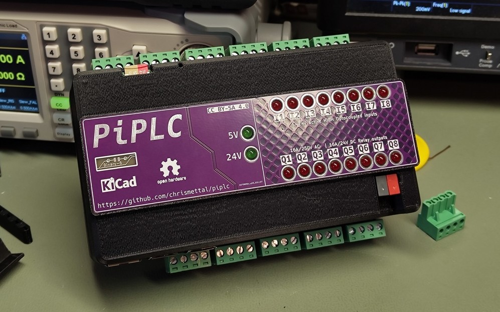
This is a Raspberry Pi breakout board + DIN rail case to use Pis in PLC-like industrial situations.
The design relies on a Raspberry Pi 4 for all functions to work. Pi 5 does also work but won't fit the 3D printed case, while Pi 3 and below don't allow for all functions to be used.
The PiPLC is intended to be used with Home Assistant, as well as OpenPLC. Obviously, since it's just a breakout board for any Pi, you can run whatever software you want, but Home Assistant and OpenPLC are the ones inspiring the design of this project.
For an example use with your own software, check out Grass!
IO featured on board the PLC are:
All the parts are or will be stocked at Tindie!

If you like my work please consider supporting me!
| GPIO Name | PiPLC function | OpenPLC | Home Assistant | Codesys |
|---|---|---|---|---|
GPIO_02 | :blue_square: I²C SDA | :warning: No driver yet | :warning: To be tested | :warning: To be tested |
GPIO_03 | :blue_square: I²C SCL | :warning: No driver yet | :warning: To be tested | :warning: To be tested |
GPIO_04 | :blue_square: Modbus TX | /dev/ttyAMA3 | /dev/ttyAMA3 | :warning: To be tested |
GPIO_05 | :blue_square: Modbus RX | /dev/ttyAMA3 | /dev/ttyAMA3 | :warning: To be tested |
GPIO_06 | :blue_square: Modbus RTS | /dev/ttyAMA3 | /dev/ttyAMA3 | :warning: To be tested |
GPIO_07 | :red_square: Q4 | %QX0.3 | :white_check_mark: | :warning: To be tested |
GPIO_08 | :red_square: Q3 | %QX0.2 | :white_check_mark: | :warning: To be tested |
GPIO_09 | :yellow_square: I5 | %IX0.4 | :white_check_mark: | :warning: To be tested |
GPIO_10 | :yellow_square: I4 | %IX0.3 | :white_check_mark: | :warning: To be tested |
GPIO_11 | :yellow_square: I6 | %IX1.5 | :white_check_mark: | :warning: To be tested |
GPIO_12 | :red_square: Q5 | %QX0.4 | :white_check_mark: | :warning: To be tested |
GPIO_13 | :yellow_square: I7 | %IX0.6 | :white_check_mark: | :warning: To be tested |
GPIO_14 | :blue_square: KNX TX | :x: | /dev/ttyAMA0 | :warning: To be tested |
GPIO_15 | :blue_square: KNX RX | :x: | /dev/ttyAMA0 | :warning: To be tested |
GPIO_16 | :red_square: Q6 | %QX0.5 | :white_check_mark: | :warning: To be tested |
GPIO_17 | :yellow_square: I1 | %IX0.0 | :white_check_mark: | :warning: To be tested |
GPIO_18 | :orange_square: PWM_0 | %QW0 | :white_check_mark: | :warning: To be tested |
GPIO_19 | :orange_square: PWM_1 | %QW1 | :white_check_mark: | :warning: To be tested |
GPIO_20 | :red_square: Q7 | %QX0.6 | :white_check_mark: | :warning: To be tested |
GPIO_21 | :red_square: Q8 | %QX0.7 | :white_check_mark: | :warning: To be tested |
GPIO_22 | :yellow_square: I3 | %IX0.2 | :white_check_mark: | :warning: To be tested |
GPIO_23 | :blue_square: 1-Wire | :warning: No driver yet | :white_check_mark: | :warning: To be tested |
GPIO_24 | :red_square: Q1 | %QX0.0 | :white_check_mark: | :warning: To be tested |
GPIO_25 | :red_square: Q2 | %QX0.1 | :white_check_mark: | :warning: To be tested |
GPIO_26 | :yellow_square: I8 | %IX0.7 | :white_check_mark: | :warning: To be tested |
GPIO_27 | :yellow_square: I2 | %IX0.1 | :white_check_mark: | :warning: To be tested |
Pins marked unusable with OpenPLC are either not broken out, or differ too much from OpenPLC's mapping. As OpenPLC's mapping is immutable, these pins might not be used if PiPLC is used with the OpenPLC runtime and Pi default hardware layer.

| 1 | 2 | 3 | 4 |
|---|---|---|---|
+24 V | +24 V | GND | GND |
The PiPLC is to be supplied with 24 V and requires at least a 1 A power supply under full load.
While it will theoretically work at 12 V, the relays used for Q1-8 require 24V coil voltage to trigger. If you are not placing the relays, feel free to supply your PLC with 12 V though.
Internally, 5V is generated by a TPS54331D based DC-DC converter.
At J10 12/24V is passed through unprotected from the power input.
At J2 and J8 5 V from the DC-DC can be used to draw up to 500mA (protected through a polyfuse).
At J3, 3V3 from the RPI can be used to draw up to 500mA (protected through a polyfuse)
| 1 | 2 | 3 | 4 |
|---|---|---|---|
+5 V | :blue_square: Modbus B | :blue_square: Modbus A | GND |
Modbus is an industrial communication protocol often used with PLCs communicating with I/O extensions or other PLCs.
The wire based one used here is called Modbus RTU and is based on half-duplex RS-485 so the header can also be used for that if you dislike Modbus.
OpenPLC natively supports Modbus to talk to I/O, while Home Assistant has a Modbus integration.
[!NOTE]
To enable Modbus on your Pi, make sure to enableUART3at GPIO5/06. This UART is not enabled by default and is only present on Raspberry Pi models 4 and up!We do NOT enable the
ctsrtsoption as we don't want to run with hardware handshakes. We do however need to set/unset theDE/NREpins of the RS485 transceiver IC. How to do this differs based on the chose OS.In
/boot/config.txtadd:
dtoverlay=uart3and reboot afterwards
After rebooting you should see the new serial port
/dev/ttyAMA3when executingls /dev/tty*For OpenPLC, if you followed the installation guide you should have installed my fork that includes
DE/NREcontrol viaGPIO_6so there should be nothing else for you to do
https://raspberrypi.stackexchange.com/questions/104464/where-are-the-uarts-on-the-raspberry-pi-4
J3
| 1 | 2 | 3 | 4 |
|---|---|---|---|
:red_square: Q1 | :red_square: Q1 | :red_square: Q2 | :red_square: Q2 |
J4
| 1 | 2 | 3 | 4 |
|---|---|---|---|
:red_square: Q3 | :red_square: Q3 | :red_square: Q4 | :red_square: Q4 |
J5
| 1 | 2 | 3 | 4 |
|---|---|---|---|
:red_square: Q5 | :red_square: Q5 | :red_square: Q6 | :red_square: Q6 |
J6
| 1 | 2 | 3 | 4 |
|---|---|---|---|
:red_square: Q7 | :red_square: Q7 | :red_square: Q8 | :red_square: Q8 |
8 digital outputs are found at the pottom of the device. These outputs are driven by G5RL-1A-E-TV8 relays theoretically capable of 16 A at 250 V AC / 16 A at 24 V DC.
As with the digital inputs, each output features a status LED found on the HMI subboard.
[!WARNING] As this the PiPLC is an open source passion project and not externally rated by TÜV or a similar agency, usage of these relays in mains powered systems is at your own risk.
All components chosen are rated for 16 A at 250 V AC and should be capable of driving everything in a home environment.
Only certified electricians should ever be performing mains work, and home-built devices should never be connected to mains power unless you know what you are doing.
| 1 | 2 | 3 | 4 |
|---|---|---|---|
:orange_square: PWM 0 | :orange_square: PWM 1 | GND | GND |
The PWM outputs are intentionally bare, unprotected GPIO connections of GPIO_18 for PWM 0 and GPIO_19 for PWM 1 so take care not to damage the Pi here.
If choosing to use the GPIO as inputs, bear in mind that the Pi's GPIO are only 3.3 V tolerant.
Choosing to actually use the PWM outputs, you have both hardware PWM's available to you here.
[!WARNING] Unprotected access to
GPIO_18andGPIO_19. Take care not to damage your Pi!
| 1 | 2 | 3 | 4 |
|---|---|---|---|
+5 V | GND | :blue_square: I²C SDA | :blue_square: I²C SCL |
Here you have a protected, somewhat isolated 5 V tolerant I²C header with integrated pullups. This was at first intended for connecting to extensions, but the Modbus header takes care of that now. You do have the option however, to attach whatever I²C device you want, provided the runtime you are using supports I²C communication.
[!WARNING] The I²C contacts are already pulled up to 5 V so do not connect any 3.3 V only I²C devices directly without isolation!
[!NOTE] To enable I²C, go into
/boot/config.txtand uncommentdtparam=i2c_arm=on, or alternatively enable I²C throughsudo raspi-configYou might need to install
i2c-toolswithsudo apt install i2c-toolsto test your I²C connections.
i2cdetect -y 1should show the adresses of all found I²C devices afterwards
| 1 | 2 | 3 | 4 |
|---|---|---|---|
+ 3.3 V | GND | :blue_square: 1-Wire | :blue_square: 1-Wire |
This header contains GPIO_04 for native 1-Wire capability.
1-Wire is usually used for temperature sensors, like DS18B20, or battery voltage sensing, but is sometimes also used for access control with iButtons.
[!WARNING] Unprotected access to
GPIO_04. Take care not to damage your Pi!
[!NOTE] To enable 1-Wire, add the following to
/boot/config.txt:
dtoverlay=w1-gpio,gpiopin=23reboot
You should be able to find any connected 1-Wire devices automatically with
ls /sys/bus/w1/devices/afterwards
J10
| 1 | 2 | 3 | 4 |
|---|---|---|---|
+24 V | +24 V | +24 V | +24 V |
J11
| 1 | 2 | 3 | 4 |
|---|---|---|---|
:yellow_square: I4 | :yellow_square: I3 | :yellow_square: I2 | :yellow_square: I1 |
J12
| 1 | 2 | 3 | 4 |
|---|---|---|---|
:yellow_square: I8 | :yellow_square: I7 | :yellow_square: I6 | :yellow_square: I5 |
8 digital inputs are found at the top of the device. These inputs are 5-24 V tolerant current sinking inputs through EL817C optocouplers.
J10 features 24 V outputs to easily supply switches or other sensors feeding back into J11-J12 as inputs.
All inputs feature a status//Order is intentional to match the GPIO mapping table of PiPLC at https://github.com/chrismettal/piplc#gpio-mapping //while having all relays mapped "in order" from left to right LED driven by the optocoupler output, thus not loading the input.
On the Raspberry side, pullups need to be enabled on the GPIOs to enable reading from these input stages.
The inputs require 5mA of input current to reliably trigger at 24 V.
Utilizing knxd to run a NCN5121 KNX transceiver chip the PiPLC can talk to KNX networks natively, without going through an actual KNX-IP gateway first. (Internally, knxd looks like a KNX-IP gateway, but it won't route through your actual LAN)
For Home Assistant, there is an addon for knxd, so Home Assistant sees the internal NCN5121 as a KNX-IP gateway @ localhost.
See the knxd documentation for specifics on how to use the driver if you are not using Home Assistant.
In this board, the NC5121 is NOT supplied through the KNX supply, but through the Pi's 3v3 rail. This means that it doesn't need to be taken into account when calculating the KNX power supply needs.
[!NOTE]
To enable KNX, make sure to disable bluetooth and the serial console on your Pi This is required to enable fullUART0at GPIO14/15In
/boot/config.txtadd:
dtoverlay=pi3-disable-btIn
/boot/cmdline.txtremove:
console=serial0,115200orconsole=ttyAMA0,115200if foundreboot
In your OS,
/dev/ttyAMA0can now be used as your KNX interface
A PCF8523 based realtime clock is present on the board so the PiPLC can keep track of time even when its 24 V input drops.
[!NOTE]
To enable the real time clock on your Pi, add the following to
/boot/config.txt:
dtoverlay=i2c-rtc,pcf8523And reboot afterwards.
Enabling RTC in the Pi and setting the time correctly is explained well in Adafruit's RTC guide.

This is the testing "schematic" used for all software examples. It demonstrates all interfaces present on-board and all testing of PiPLC was done in this configuration.
| GPIO Name | PiPLC function | Device |
|---|---|---|
GPIO_02 - 03 | :blue_square: I²C | PCA9685 16 Ch. PWM servo driver |
GPIO_04 - 06 | :blue_square: Modbus | EBYTE MA01-XACX0440 I/O Module |
GPIO_04 - 06 | :blue_square: Modbus | ARCELI SHT20 Temp + Humidity probe |
GPIO_24 | :red_square: Q1 | 230 V Light |
GPIO_08 | :red_square: Q3 | Stacklight Green Channel |
GPIO_07 | :red_square: Q4 | Stacklight Yellow Channel |
GPIO_12 | :red_square: Q5 | Stacklight Red Channel |
GPIO_17 | :yellow_square: I1 | S0 Home power meter |
GPIO_27 | :yellow_square: I2 | Light switch |
GPIO_22 | :yellow_square: I3 | Emergency Stop NO |
GPIO_10 | :yellow_square: I4 | Emergency Stop NC |
GPIO_09 | :yellow_square: I5 | Toggle Switch left |
GPIO_11 | :yellow_square: I6 | Toggle Switch right |
GPIO_13 | :yellow_square: I7 | Green button |
GPIO_26 | :yellow_square: I8 | Red button |
GPIO_14 - 15 | :blue_square: KNX | 4 Ch. Relay |
GPIO_18 | :orange_square: PWM_0 | Dimmable LED |
GPIO_19 | :orange_square: PWM_1 | Dimmable LED |
GPIO_23 | :blue_square: 1-Wire | DS18B20 Temperature probe |
| USB | USB | Arduino Uno (OpenPLC Slave Firmware) |
| RJ45 Jack | EtherCAT | TBD |
| Wifi | LAN access | Android Tablet as HMI |
| Wifi | LAN access | Programming device (Laptop) |
There is an example chinesium Modbus I/O module on the testing board with the following information:
| Parameter | Value |
|---|---|
| Device Type | Generic Modbus RTU Device |
| Slave ID | 32 |
| COM Port | /dev/ttyAMA3 |
| Baudrate | 9600 |
| Parity | None |
| Data bits | 8 |
| Stop bits | 1 |
| Transmission Pause | 0 |
| Discrete Inputs | Address 0, Size 0 |
| Coils | Address 0, Size 4 |
| Input Registers | Address 0, Size 0 |
| Holding Registers - Read | Address 0, Size 0 |
| Holding Registers - Write | Address 0, Size 0 |
OpenPLC is a Fully IEC 61131-3 compliant, open source, multi-hardware programmable logic controller suite.
Consisting of a separate runtime and editor, it can run on regular PCs as a soft PLC, as well as a multitude of embedded systems. (Think Beckhoff XAR / XAE)
I am currently creating a hardware layer for PiPLC at https://github.com/Chrismettal/OpenPLC_v3. This should allow easy adressing of all IO while enabling native use of Modbus and other interfaces. The regular "Rpi" layer should also be compatible, but I²C, Modbus and KNX might not work, and I1-8 / Q1-8 adressing might be a bit unintuitive (See GPIO mapping table)
You are going to need a fresh installation of Raspberry Pi OS on your Pi 4. There is an official getting started guide that is being kept up to date, so the first steps are not further described here.
Execute git clone https://github.com/chrismettal/OpenPLC_v3 on your Pi. This will clone a forked version of the OpenPLC runtime that contains some changes to make it compatible with PiPLC. Should these changes get merged, this link will be changed to point to the official version.
cd OpenPLC_v3 to enter the just cloned folder
./install rpi will start the full OpenPLC installation. (This will take a few minutes)
After a reboot, your OpenPLC installation's webinterface should be accessible on port 8080 on your Pi. Either try to access it at 127.0.0.1:8080 locally on your pi, or access it through your Pi's IP adress in your host computer.
The default credentials will be Name: openplc, Password: openplc. You might want to change these right after logging in for the first time. To do so, use the "Users" tab and edit the default "openplc" account:
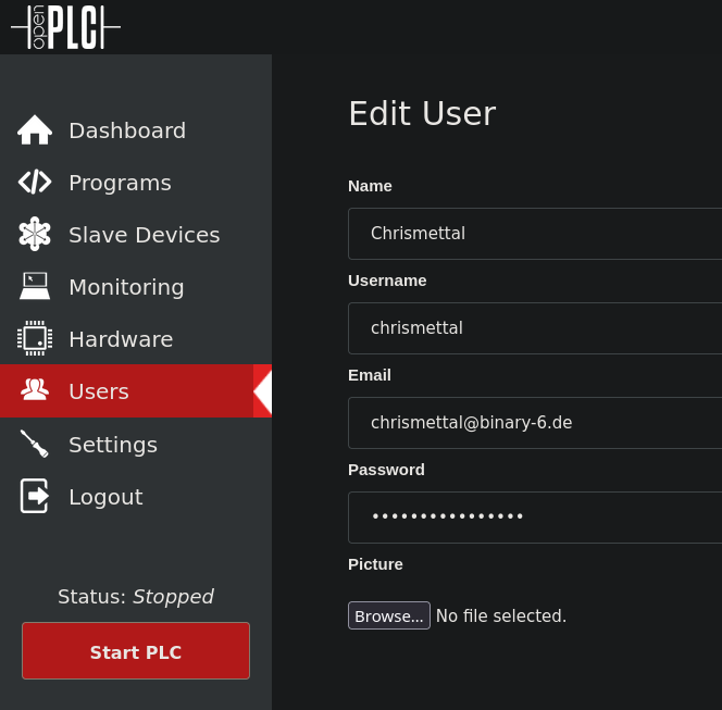
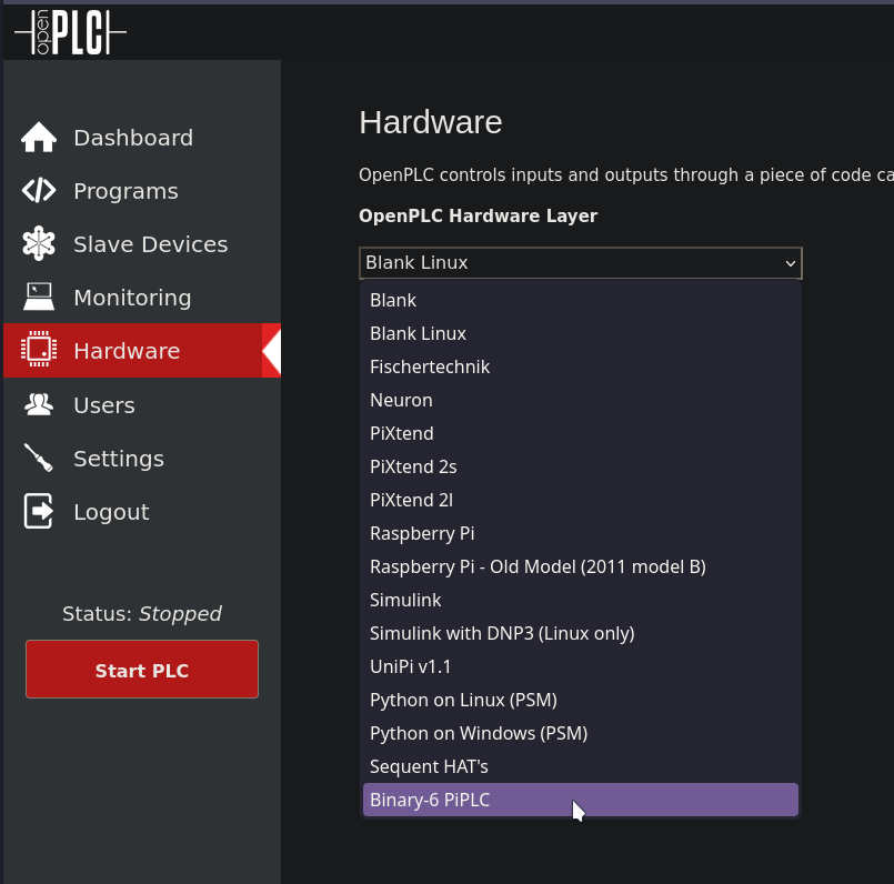
That should be it for a base installation. You should now have access to D1-8 and Q1-8 already, but you won't see Modbus RTU yet for slave devices. Instructions how to enable the Modbus COM port are found at J2 | Modbus.
After enabling UART3 as described above and rebooting your Pi, you should see /dev/ttyAMA3 be available as a COM port for Modbus slaves:
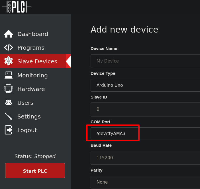
Check out /src/OpenPLC!
Home Assistant is an open source smart-home automation software, that provides logic, visualization and automation in a single place. It allows you to connect practically everything to your home under one interface, awakening your smart home.
Home Assistant seems to move away from local hardware IO a bit, instead focussing on devices in your LAN / WiFi. That doesn't mean though, that it isn't fully capable of running on an actual PLC, giving you control of your devices without a middle man or WiFi shenanigans. This is where the NC5121 KNX interface comes into play, which enables you to talk to a vast variety of off-the-shelf decentralised ACTUAL smart home components (No supplier apps, no accounts, no telemetry) without needing to go through an KNX-IP interface first.
Follow the official first steps for a standard Home Assistant Raspberry Pi installation
Also follow the official onboarding steps to create your Home Assistant account and generally be able to use the system
Power down your Home Assistant install and take out the SD card
Install the SD card in a linux computer
Mount the first partition (Should be a 32MB one) temporarily to your system:
mkdir ~/TempMount

sudo mount -t vfat /dev/sdx1 ~/TempMount
In the now mounted TempMount directory, you will find Config.txt where we can set dtoverlays to enable additional serial ports etc.
Follow both the KNX enabling guide as well as the Modbus enabling guide, adding their specific dtoverlays to Config.txt. This will make sure the Pi knows to enable the required UART connections there.
You can now unmount the drive with sudo umount ~/TempMount and put the SD card back in your Pi before booting Home Assistant back up
To enable KNX communication, you'll need to install the knxd addon.
Configure the knxd daemon as shown in the following picture. The /dev/ttyAMA0 interface makes sure we are talking to our on-board NC5121. Theoretically you could also use a KNX-USB interface if you weren't using the PiPLC board. Don't forget to start the daemon and set it to autostart.
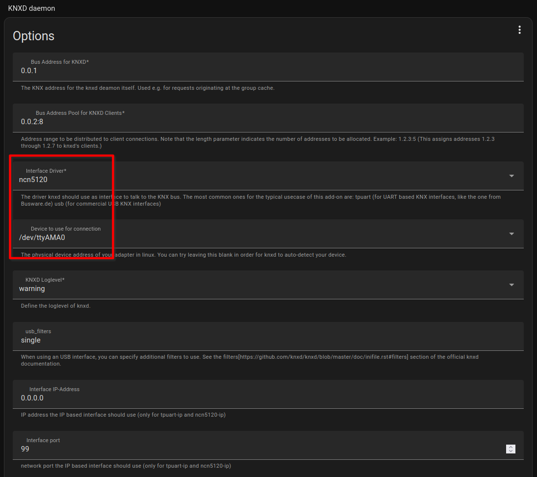
knxd deamon is running install the KNX integration:
During initial setup of the KNX integration, it should find your local knxd daemon instance as a valid interface.
To control / read your local GPIO, you'll want to install the following custom integration:
TODO Upload example configuration.yaml
Codesys, like OpenPLC is a IEC 61131-3 compliant PLC runtime, compatible with PiPLC. It is not open source and the license for the RPI runtime costs about 55€. PiPLC was designed for OpenPLC but Codesys (as of 2024-01) is a much more robust runtime with more features.
As Codesys is proprietary, I won't be focussing much on it, but I want to make sure that most functions work well with PiPLC.
Setup your Pi with a fresh install of Pi OS. I only had luck using the "legacy" 32 Bit Debian Buster install and not the most recent (as of 2024-02) Debian Bookworm. (Wiringpi?)
Follow the Codesys Pi FAQ to install the runtime on your Pi as well as to get your engineering system set up
After enabling UART3 as described above and rebooting your Pi, you can set /dev/ttyAMA3 to be your Modbus master port:
TODO Modbus port image TODO I²C port settings TODO 1-Wire port settings
Check out /src/CODESYS!
/boot/config.txt# PiPLC
dtoverlay=uart3 # Enable UART3 for Modbus
dtoverlay=pi3-disable-bt # Disable Bluetooth so that UART0 is free for KNX
dtoverlay=w1-gpio,gpiopin=23 # Enable the 1-Wire pus on pin 23
dtoverlay=i2c-rtc,pcf8523 # Enable the I²C RTC
gpio=24,25,8,7,12,16,20,21=op,dl # Set all relay pins to outputs and turn them off
gpio=17,27,22,10,9,11,13,26=ip,pu # Set all digital input pins as pulled-up inputsremove any mention of I²S or SPI if found, otherwise relay GPIOs might be driven HIGH on boot. Sometimes dtparam=spi=on is set which will ruin your day so comment that one out if found.
/boot/cmdline.txtremove console=serial0,115200 and/or console=ttyAMA0,115200 if found.
A full PiPLC consists of several subboards that need to be manufactured individually. Theoretically only the mainboard is technically required, as you could use wires to manually connect the Pi to the PLC as well as just not using the HMI as it is only a status display at the moment, but the existing 3D printable case assumes all boards to be used.
Only the main board has SMD parts that need to be assembled, so only one board will need to go through PCBA.
All boards are designed to be manufactured by JLCPCB, with BOMs using LCSC partnumbers attached. ALso all boards are to be manufactured with regular 1.6mm thickness, lead free HASL and 1oz copper weight.
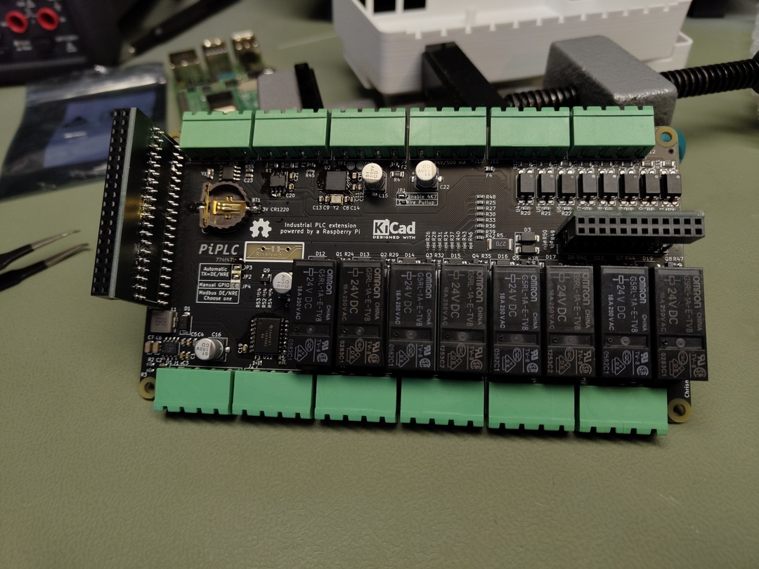
This board houses all logic and is the only one that benefits from a PCBA service. All other boards plug into here, including the Raspberry Pi.
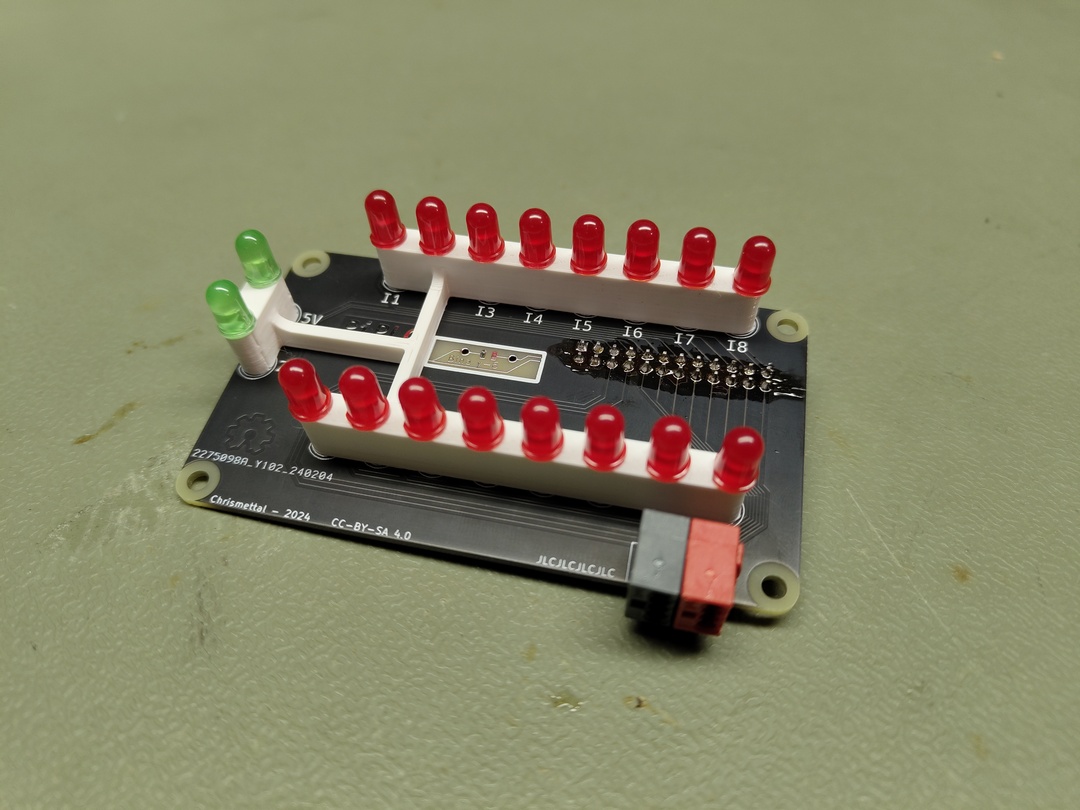
While not strictly required, this board houses frontpanel LEDs for status view of digital inputs and outputs, as well as 5V and 24V power status LEDs.
Additionally, the Wago header to plug into a KNX network is housed on this board.
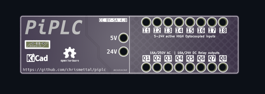
Purely for decoration / labelling. No electrical connections here. Can theoretically be replaced by a sticker.
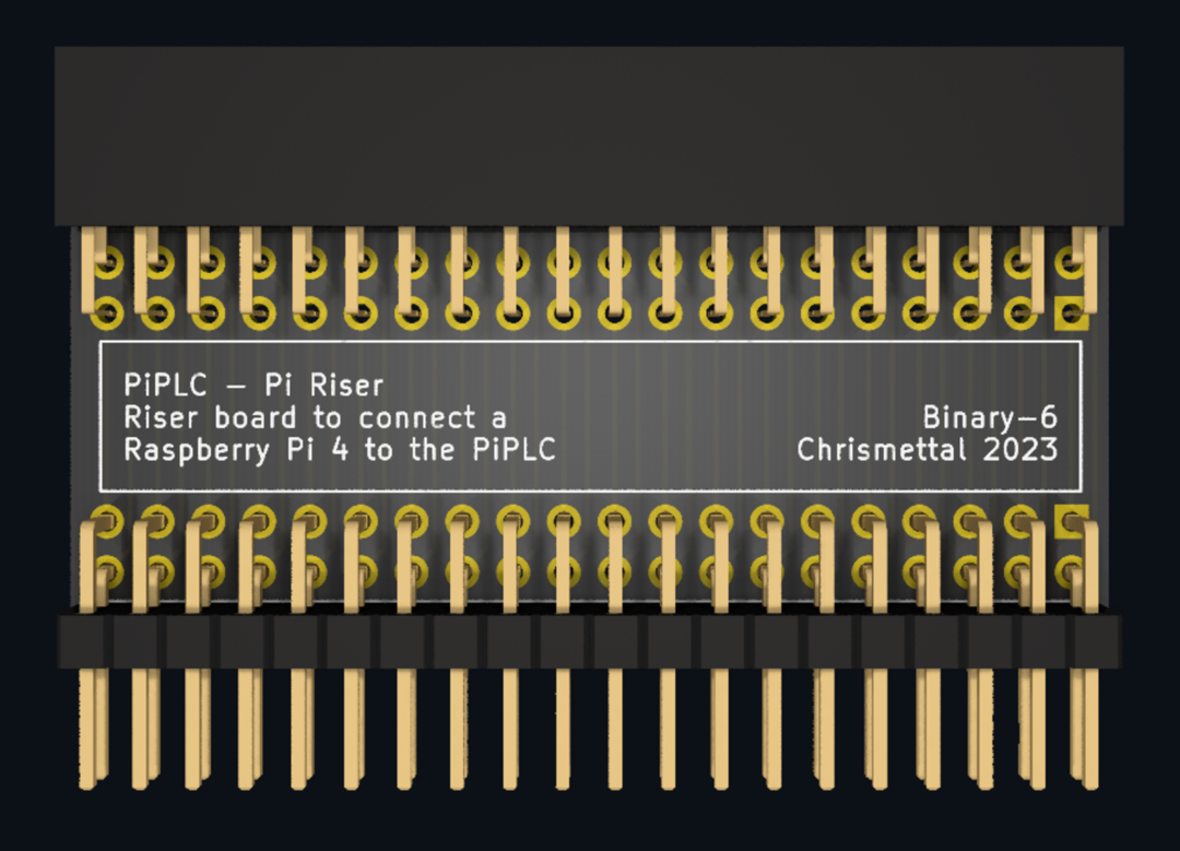
Riser board to give the Pi enough clearance to connect face-down to the mainboard. Can theoretically be replaced by a ribbon cable.
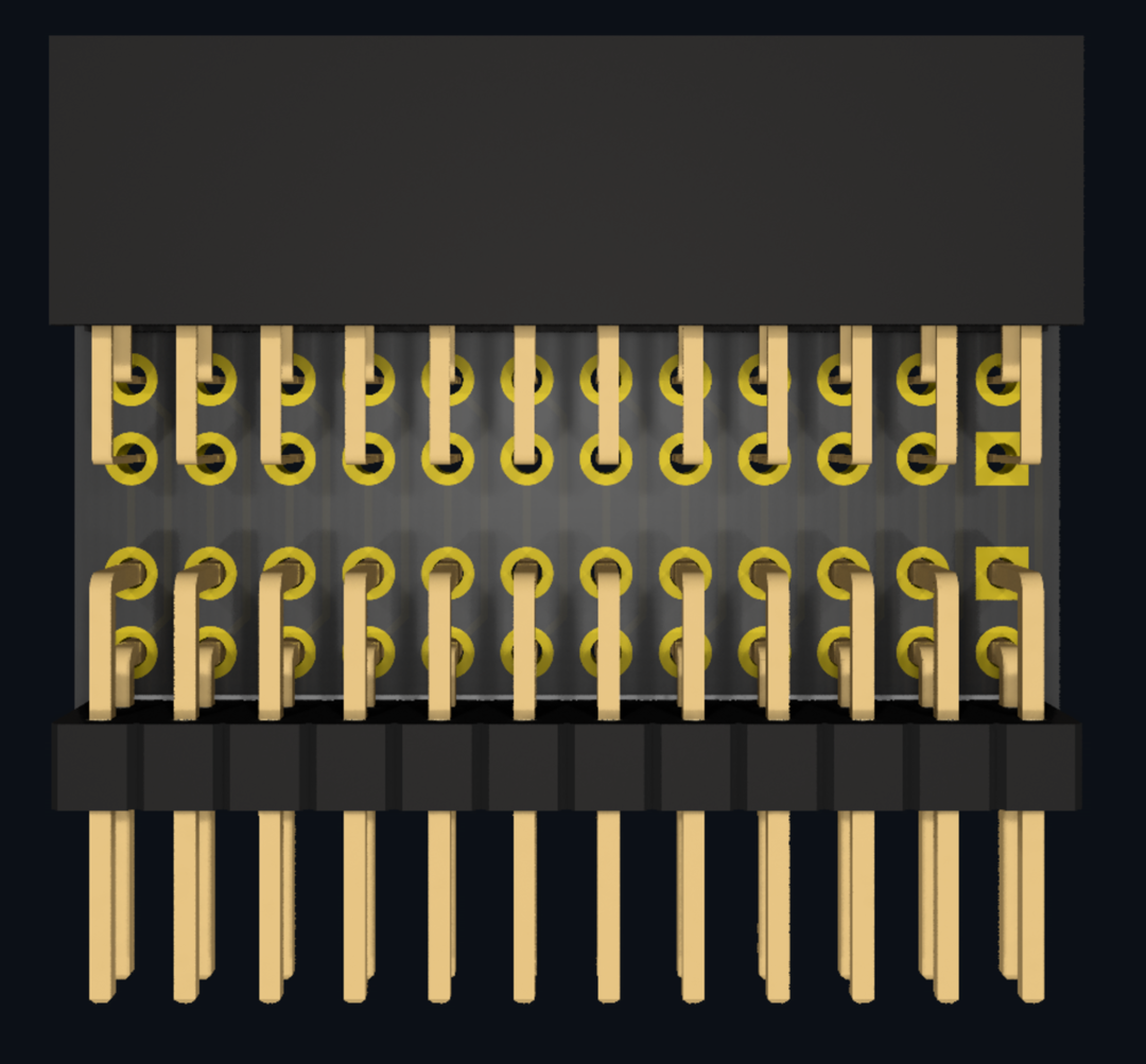
Riser board to connect the HMI board to the mainboard. Can theoretically be replaced by a ribbon cable
A 3D printable case is provided in /3d_printing.
The case just snapfits together, after all boards were installed using M3x5mm screws.
Currently it will only fit a Raspberry Pi 4 and will not work with a Pi 5! You could modify the case to make a Pi 5 fit but I haven't done that yet.
The DIN-Rail mount on the back is not optimal yet so the compliant snap-action might now work, but since all boards I have manufactured are now deployed, I haven't yet gone around to updating the case.
The case is intended to be printed in a isolating and/or flame retardant filament like PC or PETG VO.
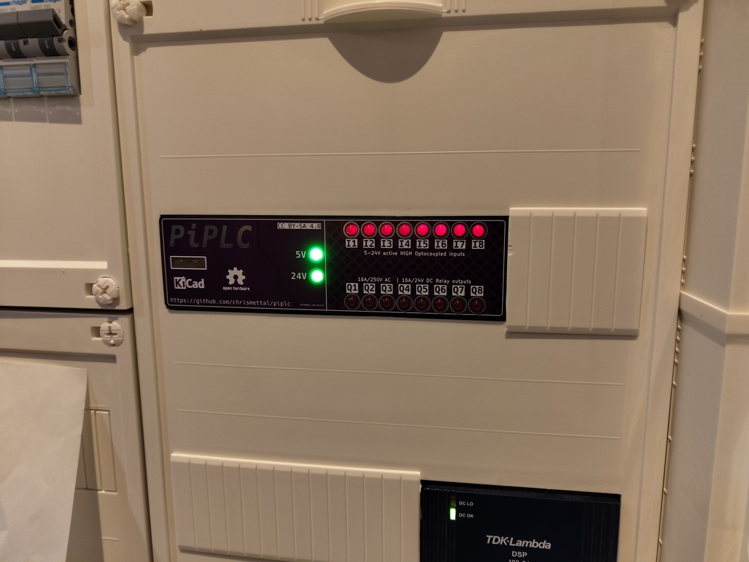
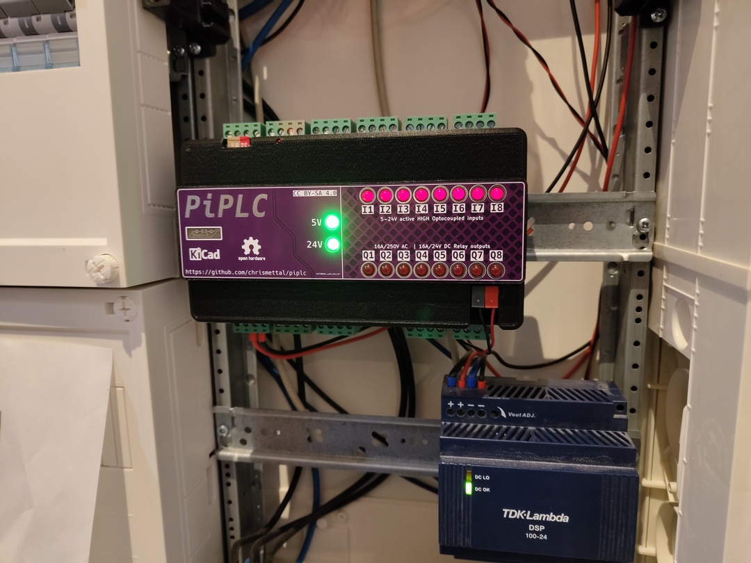
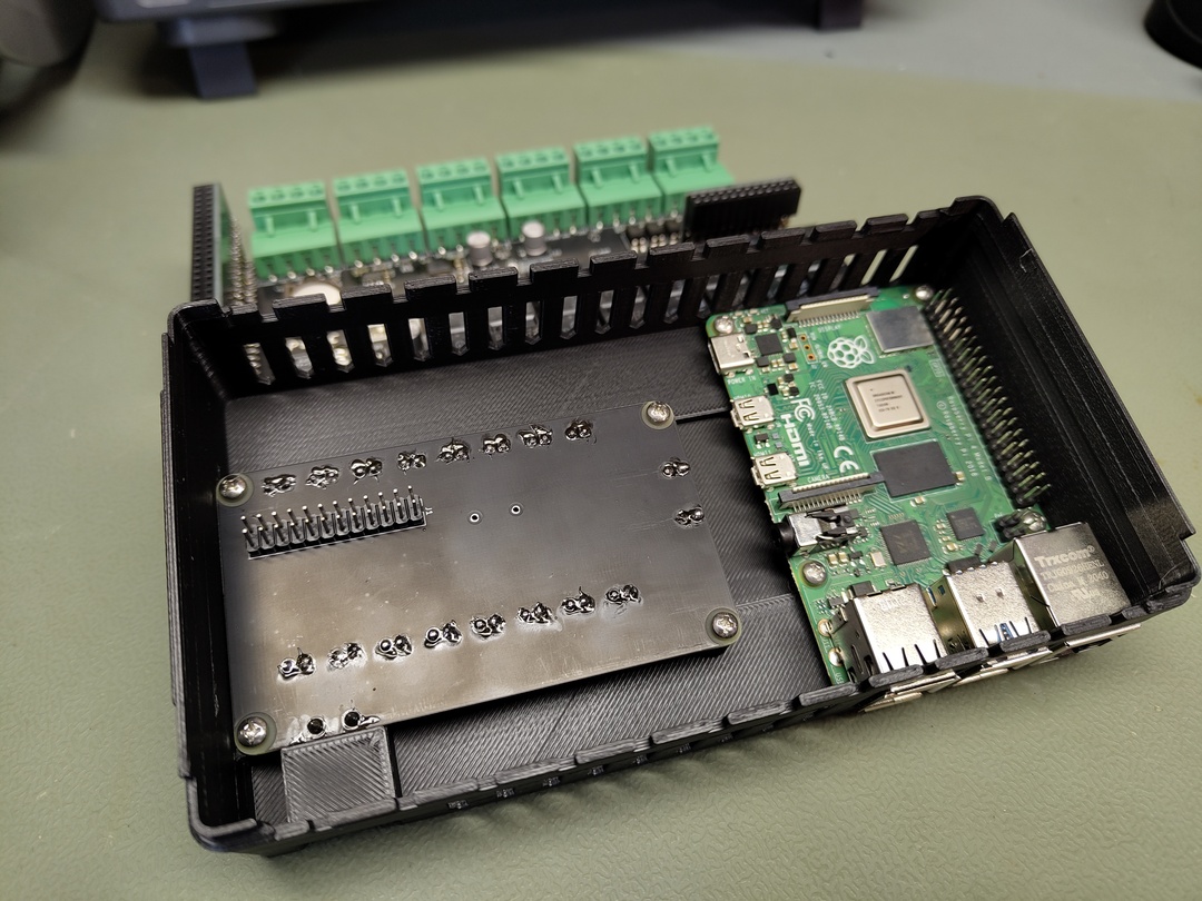
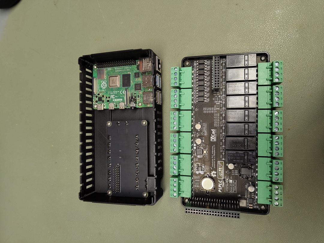
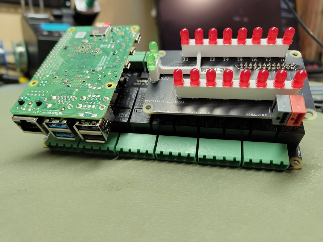
The following commands can be used to test your hardware configuration without installing PLC code or a full Home Assistant install. These are to be executed on a regular Pi OS install with raspi-gpio installed.
raspi-gpio set 17,27,22,10,9,11,13,26 pu
raspi-gpio set 24,25,8,7,12,16,20,21 op
raspi-gpio get 17,27,22,10,9,11,13,26
raspi-gpio set 24 dh / raspi-gpio set 24 dl
i2cdetect -y 1
If you like my work please consider supporting me!

This work is licensed under a Creative Commons Attribution-ShareAlike 4.0 International License.
| Qty | Value | Footprint | References |
|---|---|---|---|
| 17 | 1K2 | Resistor_SMD:R_0603_1608Metric | R16, R17, R18, R19, R20, R21, R22, R23, R25, R27, R30, R33, R36, R39, R42, R48 +1 |
| 12 | WJ2EDGRC-5.08-4P | Connector_Phoenix_MSTB:PhoenixContact_MSTBA_2,5_4-G-5,08_1x04_P5.08mm_Horizontal | J1, J2, J3, J4, J5, J6, J7, J8, J9, J10, J11, J12 |
| 11 | 10K | Resistor_SMD:R_0603_1608Metric | R2, R24, R29, R32, R35, R38, R41, R44, R47, R52, R53 |
| 11 | 4K7 | Resistor_SMD:R_1206_3216Metric | R4, R6, R7, R8, R9, R10, R11, R12, R13, R14, R15 |
| 9 | SS14 | Diode_SMD:D_SMA | D2, D12, D13, D14, D15, D16, D17, D18, D19 |
| 8 | 100R | Resistor_SMD:R_0603_1608Metric | R26, R28, R31, R34, R37, R40, R43, R46 |
| 8 | AO3400A | Package_TO_SOT_SMD:SOT-23-3 | Q1, Q2, Q3, Q4, Q5, Q6, Q7, Q8 |
| 8 | EL817C | MeineBib:Optocoupler_DIP_S1 | U4, U5, U6, U7, U8, U9, U10, U11 |
| 8 | G5RL-1A-E-TV8 DC24 | MeineBib:Relay_SPST_Omron_G2RL-1A-E_GroundMod | K1, K2, K3, K4, K5, K6, K7, K8 |
| 7 | 100nF | Capacitor_SMD:C_0603_1608Metric | C12, C13, C14, C18, C19, C20, C21 |
| 4 | 100uF | Capacitor_SMD:CP_Elec_6.3x7.7 | C15, C16, C17, C22 |
| 4 | 500mA | Fuse:Fuse_0805_2012Metric | F1, F2, F3, F4 |
| 4 | Mounting_Hole | MeineBib:EigenesMountingHole_3.2mm_M3_Small | MK2, MK2, MK2, MK2 |
| 3 | 10nF | Capacitor_SMD:C_0603_1608Metric | C1, C2, C3 |
| 2 | 10pF | Capacitor_SMD:C_0603_1608Metric | C8, C9 |
| 2 | 47uF | Capacitor_SMD:C_1206_3216Metric | C6, C7 |
| 2 | TestPoint | TestPoint:TestPoint_Pad_D2.0mm | TP1, TP2 |
| 1 | 1-Wire Pullup | Jumper:SolderJumper-2_P1.3mm_Open_TrianglePad1.0x1.5mm | JP1 |
| 1 | 1.8k | Resistor_SMD:R_0603_1608Metric | R3 |
| 1 | 100K | Resistor_SMD:R_0603_1608Metric | R49 |
| 1 | 120R | Resistor_SMD:R_0603_1608Metric | R51 |
| 1 | 15k | Resistor_SMD:R_0603_1608Metric | R45 |
| 1 | 16MHz | Crystal:Crystal_SMD_3225-4Pin_3.2x2.5mm | Y2 |
| 1 | 2.2µF | Capacitor_SMD:C_0603_1608Metric | C23 |
| 1 | 220nF | Capacitor_SMD:C_0805_2012Metric | C10 |
| 1 | 27R | Resistor_SMD:R_2512_6332Metric | R5 |
| 1 | 32.768kHz | Crystal:Crystal_SMD_3215-2Pin_3.2x1.5mm | Y1 |
| 1 | 33pF | Capacitor_SMD:C_0603_1608Metric | C5 |
| 1 | 4.7nF | Capacitor_SMD:C_0603_1608Metric | C4 |
| 1 | 47K | Resistor_SMD:R_0603_1608Metric | R1 |
| 1 | 47nF | Capacitor_SMD:C_0603_1608Metric | C11 |
| 1 | 6.8uH | MeineBib:Sunltech_SLO0630H | L1 |
| 1 | 7K5 | Resistor_SMD:R_0603_1608Metric | R54 |
| 1 | Auto_DE/NRE_1 | Jumper:SolderJumper-2_P1.3mm_Open_TrianglePad1.0x1.5mm | JP3 |
| 1 | Auto_DE/NRE_2 | Jumper:SolderJumper-2_P1.3mm_Open_TrianglePad1.0x1.5mm | JP2 |
| 1 | B340 | Diode_SMD:D_SMA | D1 |
| 1 | CR1220 (3V) | MeineBib:CR1220_Holder | BT1 |
| 1 | Conn_02x12_Odd_Even | Connector_PinSocket_2.54mm:PinSocket_2x12_P2.54mm_Vertical | J17 |
| 1 | GPIO23_DE/NRE | Jumper:SolderJumper-2_P1.3mm_Open_TrianglePad1.0x1.5mm | JP4 |
| 1 | ISO1540 | Package_SO:SOIC-8_3.9x4.9mm_P1.27mm | U3 |
| 1 | ISO3082DWR | Package_SO:SOIC-16W_7.5x10.3mm_P1.27mm | U12 |
| 1 | NCN5121 | Package_DFN_QFN:QFN-40-1EP_6x6mm_P0.5mm_EP4.6x4.6mm | U2 |
| 1 | PCF8523T | Package_SO:SOIC-8_3.9x4.9mm_P1.27mm | U13 |
| 1 | Rpi GPIO | Connector_PinSocket_2.54mm:PinSocket_2x20_P2.54mm_Vertical | J99 |
| 1 | SMAJ40CA | Diode_SMD:D_SMA | D3 |
| 1 | SS8550 Y2 | Package_TO_SOT_SMD:SOT-23 | Q9 |
| 1 | Symbol_Binary6 | MeineBib:Binary_6_v0.1 | H7 |
| 1 | TPS54331D | Package_SO:SOIC-8_3.9x4.9mm_P1.27mm | U1 |
The 151 most common of 154 parts.


Arockiyalipson/Rapid-CoreX
A PCB Board with Various Communication protocols

czalinski/ThlHwTestDevices
KiCad designs, firmware and documentation for circuits that support testing of electrical hardware, such as HASS and HALT testing.

andrzejkasica/CO-sensor
Project based on ME2-CO gas sensor with current loop and 2 relays output.

punkfab/pcb-corpus
235 real KiCad boards from open-source hardware repositories, prepared as a placement and routing benchmark

MrBlahhhh/esp32-shield-can1-can2-kdcan-analogin-sdcard
A carrier board an ESP32-S3-DevKitC-1 plugs into, turning it into a vehicle data logger. The dev board brings the MCU and its power; this board brings everything that has to touch a car.


ha-y-z/Diplom-Thesis-Smart-Solar-Seeker
My high school diploma thesis about a solar panel which seeks to the sun by itself.

Harshad-vali/esp32-stereo-audio-recorder
ESP32-WROOM-32 based stereo audio recorder with dual I2S MEMS microphones, RTC timestamping, and microSD logging. KiCad hardware design + manufacturing files.
It measures 158 × 85 mm and has 2 copper layers, 1.6 mm thick.
154 parts, built around the ISO3082DWR, TPS54331D, EL817C and ISO1540D. The full list of its parts is on this page, with links to each part's symbol and footprint where PCBKit's library has them.
From the Chrismettal/PiPLC repository on GitHub, at the commit this page was made from: the board is pcb/PiPLC-Mainboard/PiPLC-Mainboard.kicad_pcb and its schematic pcb/PiPLC-24VDO/PiPLC-24VDO.kicad_sch. PCBKit opens the board in the browser, with nothing to install.
Its repository states no licence, so its author keeps all rights: ask Chrismettal before reusing the design.