
2 layers100 × 100 mm
Smart air
meeTeam05/smart-air
Devices provision over BLE, publish telemetry/shadow over MQTT, and serve the app through a Cloudflare-fronted Fastify API. See Features below for the full breakdown.
70 parts1MIT
ESP32-based IoT environmental monitoring project semester 2 2025-2026 HCMUTE
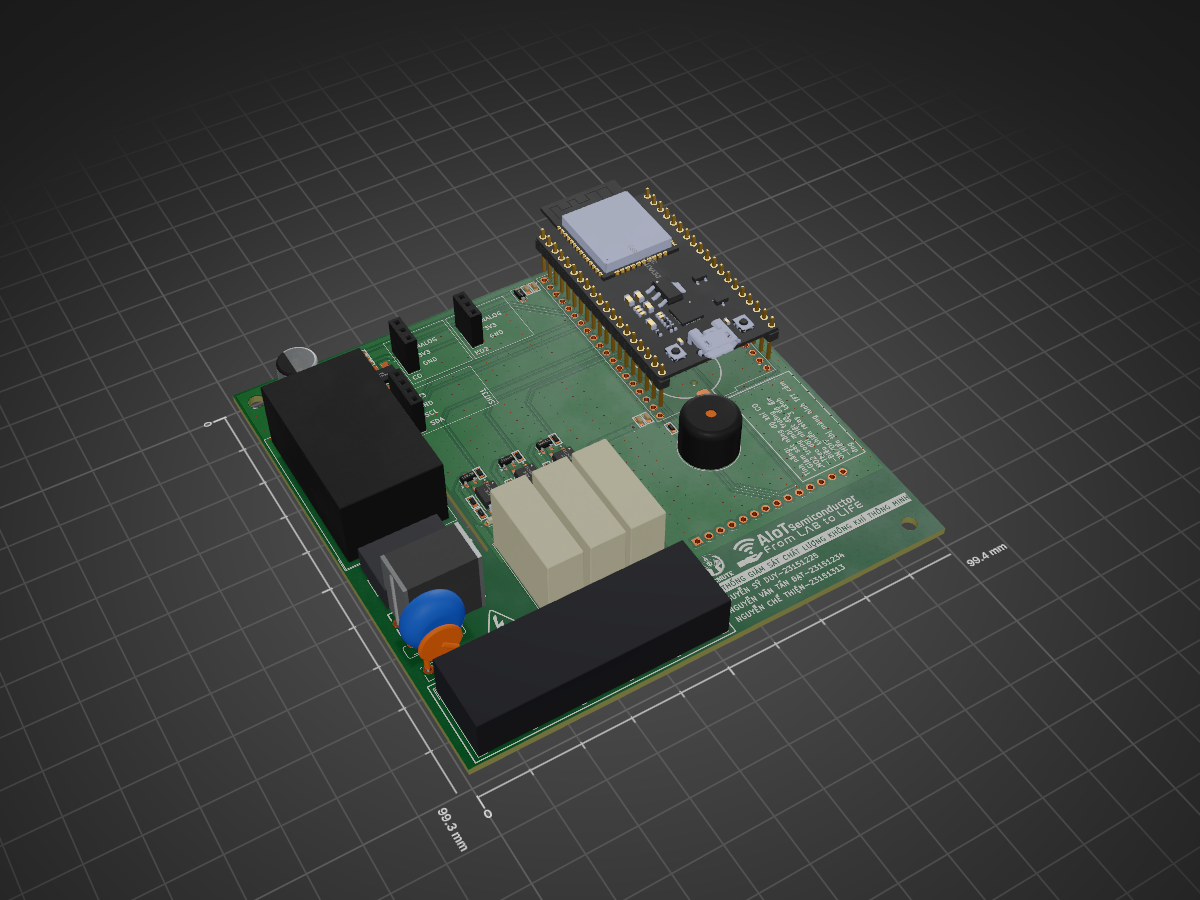
IoT2526 HK2 is an open-source printed circuit board by Chethien1912, from the Chethien1912/IoT-Environmental-Monitoring-System repository on GitHub, published under the MIT licence. It is a 2-layer board of 99.4 × 99.3 mm with 78 parts on 70 nets, routed with 283 tracks and 437 vias.
It is built around the HLK-PM01, EL357N-G and AMS1117, with the SI2300, BAT54C and BZT52C5V1 among its other parts. Its parts include 21 resistors, 13 capacitors, 10 diodes, 7 ICs and 4 transistors. It belongs with the ESP32 boards of this library.


Hệ thống giám sát môi trường thời gian thực sử dụng ESP32, được thiết kế để đo và theo dõi các thông số nhiệt độ, độ ẩm, khí CO và khí NO2. Dự án kết hợp phần cứng nhúng, giao diện hiển thị tại thiết bị, backend lưu trữ dữ liệu và ứng dụng giám sát từ xa, phù hợp cho các mô hình phòng thí nghiệm, lớp học, nhà xưởng nhỏ hoặc khu vực cần cảnh báo chất lượng không khí cục bộ.
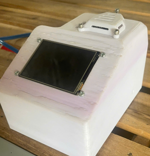
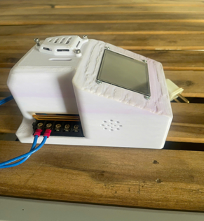
Thiết bị có thể hoạt động độc lập với màn hình cảm ứng tại chỗ, đồng thời đồng bộ dữ liệu lên backend khi có WiFi. Người dùng có thể quan sát thông số đo, thay đổi ngưỡng cảnh báo, chuyển chế độ điều khiển tự động/thủ công và theo dõi trạng thái relay, buzzer thông qua giao diện thiết bị hoặc ứng dụng.
| Mặt trước thiết bị | Góc nhìn tổng thể |
|---|---|
 |  |
| Giao diện chế độ tự động | Giao diện chế độ thủ công |
|---|---|
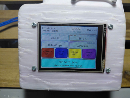 | 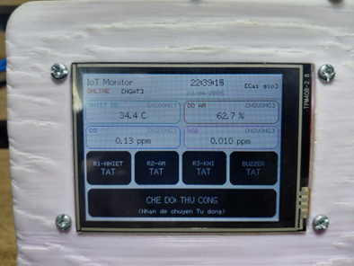 |
Auto: tự động bật/tắt relay dựa trên ngưỡng nhiệt độ, độ ẩm, CO và NO2.Manual: người dùng bật/tắt relay trực tiếp trên màn hình hoặc từ ứng dụng.ESP32 + cảm biến + relay + buzzer + TFT
|
| HTTP / WiFi
v
Backend Fastify + SQLite + MQTT + Socket.IO
|
| REST API / realtime
v
Ứng dụng Flutter giám sát và điều khiểnFirmware ESP32 được tổ chức theo các module riêng cho cảm biến, WiFi, RTC, relay, giao diện và bộ điều phối chính. AppController chạy nhiều task FreeRTOS để tách riêng cập nhật giao diện, đọc cảm biến, điều khiển relay và đồng bộ backend, giúp thiết bị phản hồi ổn định hơn khi vừa hiển thị vừa truyền dữ liệu.
Backend đóng vai trò trung gian lưu dữ liệu thiết bị, quản lý trạng thái điều khiển mong muốn, nhận telemetry từ ESP32 và phát cập nhật realtime cho ứng dụng. Frontend Flutter cung cấp giao diện đăng nhập, danh sách thiết bị, trang chi tiết thiết bị, biểu đồ/chỉ số đo và quản lý người dùng.
.
├── Code/
│   ├── backend/backend/          # Backend Fastify, SQLite, MQTT, Socket.IO
│   ├── firmware/IoT_ESP32_Local/ # Firmware ESP32 Arduino/C++
│   └── frontend/                 # Ứng dụng Flutter
├── PCB/                          # File thiết kế PCB KiCad, BOM và Gerber
├── Solidwork/                    # Mô hình cơ khí và file STEP
├── images/                       # Hình ảnh thiết bị và giao diện thực tế
├── LICENSE
└── README.mdbetter-sqlite3), JWT, MQTT.js, Socket.IO.cd Code/backend/backend
npm install
npm run seed
npm run devBackend mặc định chạy tại:
http://localhost:3000Tài khoản mặc định sau khi seed:
Username: admin
Password: Admin@123
Firmware nằm tại:
Code/firmware/IoT_ESP32_LocalMở file IoT_ESP32_Local.ino bằng Arduino IDE hoặc môi trường tương thích ESP32, cài các thư viện cần thiết cho màn hình TFT, cảm ứng, WiFi và cảm biến, sau đó nạp chương trình vào ESP32. Khi thiết bị khởi động, hệ thống sẽ đọc cảm biến định kỳ, cập nhật màn hình, xử lý điều khiển relay/buzzer và đồng bộ dữ liệu với backend nếu đã cấu hình WiFi và Backend URL.
Ứng dụng nằm tại:
Code/frontendChạy ứng dụng:
cd Code/frontend
flutter pub get
flutter run
Ứng dụng dùng API backend để đăng nhập, lấy danh sách thiết bị, xem dữ liệu realtime và gửi lệnh điều khiển.
Code/backend/backend/.env.example.PCB.Solidwork.| Qty | Value | Footprint | References |
|---|---|---|---|
| 10 | 10K | IVS_FOOTPRINTS:R_0603 | R4, R5, R6, R7, R8, R9, R12, R18, R20, R21 |
| 5 | 100nF | IVS_FOOTPRINTS:C_0603 | C2, C6, C7, C8, C9 |
| 5 | 10K/0603/1% | IVS_FOOTPRINTS:R_0603 | R1, R2, R3, R10, R11 |
| 5 | 1uF | IVS_FOOTPRINTS:C_0603 | C1, C3, C4, C5, C11 |
| 4 | LED | IVS_FOOTPRINTS:LED_0603_1608Metric | D1, D2, D3, D8 |
| 4 | SI2300 | Package_TO_SOT_SMD:SOT-23 | Q1, Q2, Q3, Q4 |
| 3 | 1N4007 | Diode_SMD:D_SOD-123F | D4, D5, D6 |
| 3 | EL357N-G | MY_FOOTPRINT:OPTO_EL357N-G | U1, U2, U3 |
| 3 | G5NB | Relay_THT:Relay_SPST_Omron_G5NB | K1, K2, K3 |
| 2 | 4.7K | IVS_FOOTPRINTS:R_0603 | R16, R17 |
| 1 | 100 | IVS_FOOTPRINTS:R_0603 | R19 |
| 1 | 10mH/UU9.8 | IVS_FOOTPRINTS:ACFilterChoke-UU9.8 | L1 |
| 1 | 10uF | IVS_FOOTPRINTS:C_0603 | C12 |
| 1 | 1K | IVS_FOOTPRINTS:R_0603 | R14 |
| 1 | 1K/0603/1% | IVS_FOOTPRINTS:R_0603 | R15 |
| 1 | 220uF | Capacitor_SMD:CP_Elec_8x10.5 | C13 |
| 1 | AMS1117 | IVS_FOOTPRINTS:SOT233 | U4 |
| 1 | BAT54C | IVS_FOOTPRINTS:SOT23-3 | D9 |
| 1 | BZT52C5V1 | Diode_SMD:D_SOD-123 | D7 |
| 1 | Buzzer | IVS_FOOTPRINTS:Buzzer-THT-12x9.5_RM7.6 | BZ1 |
| 1 | CO | Connector_PinSocket_2.54mm:PinSocket_1x03_P2.54mm_Vertical | J1 |
| 1 | CR1220 | IVS_FOOTPRINTS:BatteryHolder-SMD-CR1220 | BT1 |
| 1 | DEVKIT_V1_ESP32-WROOM-32 | MY_FOOTPRINT:MODULE_DEVKIT_V1_ESP32-WROOM-32 | U5 |
| 1 | Fuse | IVS_FOOTPRINTS:Fuse_Bourns_MF-RG300 | F1 |
| 1 | HLK-PM01 | Converter_ACDC:Converter_ACDC_Hi-Link_HLK-PMxx | PS1 |
| 1 | LED | LED_SMD:LED_0603_1608Metric | D10 |
| 1 | LOGO | MY_FOOTPRINT:AIoT_Logo | G*** |
| 1 | LOGO | MY_FOOTPRINT:Warning | G*** |
| 1 | LOGO | MY_FOOTPRINT:HCMUTE | G*** |
| 1 | NO2 | Connector_PinSocket_2.54mm:PinSocket_1x03_P2.54mm_Vertical | J2 |
| 1 | RTC_DS3231M | Package_SO:SOIC-16W_7.5x10.3mm_P1.27mm | IC1 |
| 1 | R_Variable | IVS_FOOTPRINTS:Varistor-RV-Disc-D12mm-W5.8mm-P7.5mm | R13 |
| 1 | SHT31 | Connector_PinSocket_2.54mm:PinSocket_1x04_P2.54mm_Vertical | J3 |
| 1 | Screw_Terminal_01x05 | MY_FOOTPRINT:HB9500-5P | J4 |
| 1 | Tụ kẹo 100nF 275V | IVS_FOOTPRINTS:C-Polyester-Rect-L16.5mm-W5.0mm-P15.00mm-MKT | C10 |
| 1 | ~ | MY_FOOTPRINT:TFT-ILI9341 | U6 |
The 70 most common of 78 parts.
meeTeam05/smart-air
Devices provision over BLE, publish telemetry/shadow over MQTT, and serve the app through a Cloudflare-fronted Fastify API. See Features below for the full breakdown.

PHAP0610/ThaoRDBoard
All file include and source in this: https://github.com/nguyentrungthao/STM32/tree/dev

NguyenThanhHuy-debug/PCB_Real-Time-Power-Monitoring-System-Development-Light-Switch
PCBReal-Time-Power-Monitoring-System-Development-Light-Switch — a software project built with modern tooling.

luftaquila/monolith
DIY wireless real-time datalogging platform for Student Formula and Baja.

luftaquila/fsk-energymeter
E-Formula electric energy meter for Formula Student Korea


zinedkahitaf-lang/AKD-SAFE-SourceControl
Infrastructure-Based Active Engineering Safety Platform. Move the safety burden from the worker to the hazard. Engineering prototype - not a certified safety device.

It measures 99.4 × 99.3 mm and has 2 copper layers, 1.6 mm thick.
78 parts, built around the HLK-PM01, EL357N-G, AMS1117 and SI2300. The full list of its parts is on this page, with links to each part's symbol and footprint where PCBKit's library has them.
From the Chethien1912/IoT-Environmental-Monitoring-System repository on GitHub, at the commit this page was made from: the board is PCB/IoT2526_HK2.kicad_pcb and its schematic PCB/IoT2526_HK2.kicad_sch. PCBKit opens the board in the browser, with nothing to install.
Its repository publishes it under the MIT licence: you may reuse it on that licence's terms (keep the author's notice, and for a copyleft licence share your changes alike).